Page 1041 of 1574
5C-6 CLUTCH
COMPONENT LOCATOR
CLUTCH ASSEMBLY
1 Clutch Disc
2 Clutch Cover
3 Clutch Housing
4 Release Bearing
5 Release Fork Pivot
6 Release Cylinder
7 Release Fork Boot 8 Bolt
9 Release Fork
10 Bolt 11 Spring Lock Washer
12 Transmission Input Spline
13 Release Bearing Contacting Surface
14 Contacting Point of Release Fork and Pivot
Notice
Apply the long-term grease (DBL 6811.00) to No.12,13 and 14.
Page 1044 of 1574
CLUTCH 5C-9
CLUTCH DISC Preceding Work : Removal of the transmission
1 Clutch Disc
2 Clutch Cover Assembly
3 Release Bearing
4 Clutch Housing
Tools 602 589 00 40 00 Engine Lock661 589 00 15 00 Centering Pin 5 Washer
6 Bolt
........................................................... 23 Nm
7 Washer
8 Bolt ........................................................... 44 Nm
Page 1045 of 1574
5C-10 CLUTCH Removal & Installation Procedure
1. Remove the starter motor. Install the special tool to theflywheel through the starter motor mounting holes.
Tightening Torque 47 Nm
Engine Lock 602 589 00 40 00
2. Unscren the release cylinder mounting bolts and remove the release cylinder. Installation Notice
3. Unscrew the clutch housing bolts and remove the clutch housing, release fork and release bearing.Installation Notice
4. Insert the centering pin into the clutch spline. Loosen the clutch cover bolts 1/2 turn in crisscross sequence until the spring tension is released. Notice
Do not remove the bolts at a time, or clutchcover can be damaged or deformed.
Centering Pin 661 589 00 15 00
Tightening Torque 30 - 40 Nm
Page 1048 of 1574
CLUTCH 5C-13
MASTER CYLINDER
1 Snap Pin
2 Clevis Pin
3 Clevis
4 Lock Nut
5 Flange Nut ........................................... 30-40 Nm
6 Push Rod
7 Cylinder Body
8 Oil Pipe ................................................ 15-18 Nm 9 Clamp
10 Reservoir
11 Spring
12 Piston Assembly
13 Boot
14 Plate
15 Snap Ring
Notice Do not disassemble the No.12.
Page 1050 of 1574
CLUTCH 5C-15
CLUTCH PEDAL
1 Snap Pin................................................ Replace
2 Clevis Pin ...................................... Apply Grease
3 Master Cylinder Push Rod
4 Gasket
5 Nut ....................................................... 16-22 Nm
6 Spring washer
7 Bolt ........................................................ 8-18 Nm
8 Fulcrum Pin 9 Turn Over Spring
..........................Apply Grease
10 Bushing ......................... Replace, Apply Grease
11 Full Stroke Stopper Contact Pad
12 Clutch Pedal
13 Pedal Pad
14 Pedal Mounting Bracket
15 Stopper Bolt .......................................... 21-25Nm
16 Clutch Interlock Switch
Notice
Assembly should follow the disassembly procedure in the reverse order.
Grease specification : Long - term grease (T/Mn DBL6611.00)
Page 1051 of 1574
5C-16 CLUTCH
Inspection Procedure
1. Pedal Stroke (A).Notice
To adjust the pedal stroke, loosen the lock nut (H) of the
interlock switch (G) and turn the two lock auto until the stroke is correct.
Max. Stroke 158 mm
2. Pedal Height (B). Notice
To adjust the pedal height, loosen the lock nut (C) of the
stopper bolt(D) and turn the stopper bolt until the height iscorrect.
Height (From the Floor Carpet) 147 - 187 mm
3. Pedal Free Play (E). Notice
To adjust the pedal free play, loosen the lock nut (F) of the
master cylinder and turn the push rod until the free play is correct.
4. Check the fulcrum pin and the bushing for wear, the pedal for bending and the spring for damage.
Free Play 5 - 10 Nm
Page 1053 of 1574

Model
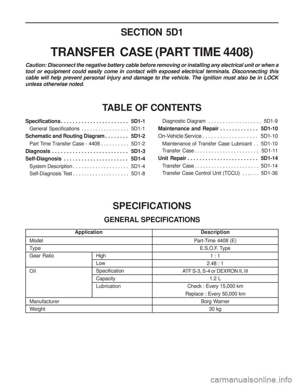
TypeGear Ratio Oil Manufacturer WeightPart-Time 4408 (E)
E.S.O.F. Type
1 : 1
2.48 : 1
ATF S-3, S-4 or DEXRON II, III
1.2 L
Check : Every 15,000 km
Replace : Every 50,000 km Borg Warner30 kg
SECTION 5D1
TRANSFER CASE (PART TIME 4408)
TABLE OF CONTENTS
SPECIFICATIONS
GENERAL SPECIFICATIONS
Caution: Disconnect the negative battery cable before removing or installing any electrical unit or when a tool or equipment could easily come in contact with exposed electrical terminals. Disconnecting thiscable will help prevent personal injury and damage to the vehicle. The ignition must also be in LOCKunless otherwise noted.
Specifications . . . . . . . . . . . . . . . . . . . . . . . 5D1-1
General Specifications . . . . . . . . . . . . . . . . . 5D1-1
Schematic and Routing Diagram . . . . . . . . 5D1-2 Part Time Transfer Case - 4408 . . . . . . . . . . 5D1-2
Diagnosis . . . . . . . . . . . . . . . . . . . . . . . . . . 5D1-3
Self-Diagnosis . . . . . . . . . . . . . . . . . . . . . . 5D1-4 System Description . . . . . . . . . . . . . . . . . . . . 5D1-4
Self-Diagnosis Test . . . . . . . . . . . . . . . . . . . . 5D1-8Diagnostic Diagram . . . . . . . . . . . . . . . . . . .
5D1-9
Maintenance and Repair . . . . . . . . . . . . . 5D1-10
On-Vehicle Service . . . . . . . . . . . . . . . . . . . 5D1-10
Maintenance of Transfer Case Lubricant . . 5D1-10
Transfer Case . . . . . . . . . . . . . . . . . . . . . . . 5D1-11
Unit Repair . . . . . . . . . . . . . . . . . . . . . . . . 5D1-14
Transfer Case . . . . . . . . . . . . . . . . . . . . . . . 5D1-14
Transfer Case Control Unit (TCCU) . . . . . . 5D1-36
High LowSpecification Capacity Lubrication
Application
Description
Page 1067 of 1574

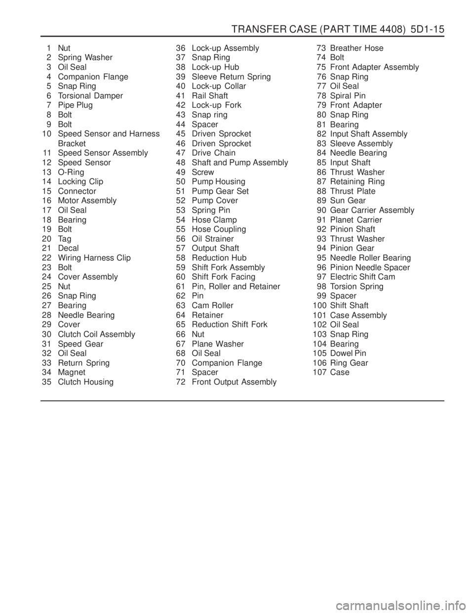
TRANSFER CASE (PART TIME 4408) 5D1-15
1 Nut
2 Spring Washer
3 Oil Seal
4 Companion Flange
5 Snap Ring
6 Torsional Damper
7 Pipe Plug
8 Bolt
9 Bolt
10 Speed Sensor and Harness
Bracket
11 Speed Sensor Assembly
12 Speed Sensor
13 O-Ring
14 Locking Clip
15 Connector
16 Motor Assembly
17 Oil Seal
18 Bearing
19 Bolt
20 Tag
21 Decal
22 Wiring Harness Clip
23 Bolt
24 Cover Assembly
25 Nut
26 Snap Ring
27 Bearing
28 Needle Bearing
29 Cover
30 Clutch Coil Assembly
31 Speed Gear
32 Oil Seal
33 Return Spring
34 Magnet
35 Clutch Housing 36 Lock-up Assembly
37 Snap Ring
38 Lock-up Hub
39 Sleeve Return Spring
40 Lock-up Collar
41 Rail Shaft
42 Lock-up Fork
43 Snap ring
44 Spacer
45 Driven Sprocket
46 Driven Sprocket
47 Drive Chain
48 Shaft and Pump Assembly
49 Screw
50 Pump Housing
51 Pump Gear Set
52 Pump Cover
53 Spring Pin
54 Hose Clamp
55 Hose Coupling
56 Oil Strainer
57 Output Shaft
58 Reduction Hub
59 Shift Fork Assembly
60 Shift Fork Facing
61 Pin, Roller and Retainer
62 Pin
63 Cam Roller
64 Retainer
65 Reduction Shift Fork
66 Nut
67 Plane Washer
68 Oil Seal
70 Companion Flange
71 Spacer
72 Front Output Assembly 73 Breather Hose
74 Bolt
75 Front Adapter Assembly
76 Snap Ring
77 Oil Seal
78 Spiral Pin
79 Front Adapter
80 Snap Ring
81 Bearing
82 Input Shaft Assembly
83 Sleeve Assembly
84 Needle Bearing
85 Input Shaft
86 Thrust Washer
87 Retaining Ring
88 Thrust Plate
89 Sun Gear
90 Gear Carrier Assembly
91 Planet Carrier
92 Pinion Shaft
93 Thrust Washer
94 Pinion Gear
95 Needle Roller Bearing
96 Pinion Needle Spacer
97 Electric Shift Cam
98 Torsion Spring
99 Spacer
100 Shift Shaft
101 Case Assembly
102 Oil Seal
103 Snap Ring
104 Bearing
105 Dowel Pin
106 Ring Gear
107 Case