2003 SSANGYONG MUSSO width
[x] Cancel search: widthPage 452 of 1574

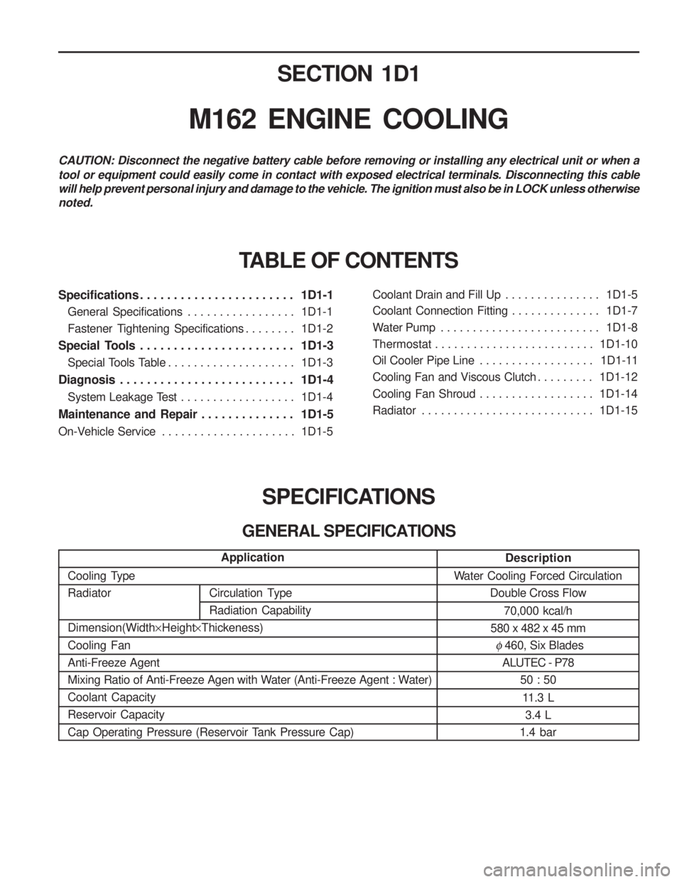
SECTION 1D1
M162 ENGINE COOLING
Specifications . . . . . . . . . . . . . . . . . . . . . . . 1D1-1General Specifications . . . . . . . . . . . . . . . . . 1D1-1
Fastener Tightening Specifications . . . . . . . . 1D1-2
Special Tools . . . . . . . . . . . . . . . . . . . . . . . 1D1-3 Special Tools Table . . . . . . . . . . . . . . . . . . . . 1D1-3
Diagnosis . . . . . . . . . . . . . . . . . . . . . . . . . . 1D1-4 System Leakage Test . . . . . . . . . . . . . . . . . . 1D1-4
Maintenance and Repair . . . . . . . . . . . . . . 1D1-5
On-Vehicle Service . . . . . . . . . . . . . . . . . . . . . 1D1-5Coolant Drain and Fill Up . . . . . . . . . . . . . . .
1D1-5
Coolant Connection Fitting . . . . . . . . . . . . . . 1D1-7
Water Pump . . . . . . . . . . . . . . . . . . . . . . . . . 1D1-8
Thermostat . . . . . . . . . . . . . . . . . . . . . . . . . 1D1-10
Oil Cooler Pipe Line . . . . . . . . . . . . . . . . . . 1D1-11
Cooling Fan and Viscous Clutch . . . . . . . . . 1D1-12
Cooling Fan Shroud . . . . . . . . . . . . . . . . . . 1D1-14
Radiator . . . . . . . . . . . . . . . . . . . . . . . . . . . 1D1-15
SPECIFICATIONS
GENERAL SPECIFICATIONS
CAUTION: Disconnect the negative battery cable before removing or installing any electrical unit or when a tool or equipment could easily come in contact with exposed electrical terminals. Disconnecting this cable will help prevent personal injury and damage to the vehicle. The ignition must also be in LOCK unless otherwisenoted.
TABLE OF CONTENTS
Description
Water Cooling Forced Circulation Double Cross Flow
70,000 kcal/h
580 x 482 x 45 mm
� 460, Six Blades
ALUTEC - P78
50 : 50
11.3 L 3.4 L
1.4 bar
Application
Cooling Type Radiator Dimension(Width ×Height ×Thickeness)
Cooling Fan Anti-Freeze Agent
Mixing Ratio of Anti-Freeze Agen with Water (Anti-Freeze Agent : Water)Coolant CapacityReservoir Capacity
Cap Operating Pressure (Reservoir Tank Pressure Cap)
Circulation Type Radiation Capability
Page 468 of 1574

Circulation Type RadiationCapabilitySECTION 1D2
M161 ENGINE COOLING
Specifications . . . . . . . . . . . . . . . . . . . . . . . 1D2-1
General Specifications . . . . . . . . . . . . . . . . . 1D2-1
Fastener Tightening Specifications . . . . . . . . 1D2-2
Special Tools . . . . . . . . . . . . . . . . . . . . . . . 1D2-3
Special Tools Table . . . . . . . . . . . . . . . . . . . . 1D2-3
Diagnosis . . . . . . . . . . . . . . . . . . . . . . . . . . 1D2-4 System Leakage Test . . . . . . . . . . . . . . . . . . 1D2-4
Maintenance and Repair . . . . . . . . . . . . . . 1D2-5
On-Vehicle Service . . . . . . . . . . . . . . . . . . . . . 1D2-5Coolant Drain and Fill Up . . . . . . . . . . . . . . .
1D2-5
Cooling Fan and Viscous Clutch . . . . . . . . . . 1D2-7
Coolant Pump . . . . . . . . . . . . . . . . . . . . . . . . 1D2-9
Thermostat . . . . . . . . . . . . . . . . . . . . . . . . . 1D2-11
Thermostat Housing Assembly . . . . . . . . . . 1D2-12
Removal and Installation of Cooling Fan Shroud . . . . . . . . . . . . . . . . . . . . . . . 1D2-14
Removal and Installation of Radiator . . . . . 1D2-15
SPECIFICATIONS
GENERAL SPECIFICATIONS
CAUTION: Disconnect the negative battery cable before removing or installing any electrical unit or when a tool or equipment could easily come in contact with exposed electrical terminals. Disconnecting this cable will help prevent personal injury and damage to the vehicle. The ignition must also be in LOCK unless otherwisenoted.
TABLE OF CONTENTS
Description
Water Cooling Forced Circulation Down Flow
61,500 kcal/h 58,000 kcal/h
680 x 415 x 25 mm680 x 415 x 28 mm
� 460, 9 Blades
ALUTEC-P78, Dragon Power Coolant A 50 : 5010.5 L 3.4 L
1.4 bar
Application
Cooling TypeRadiator Dimension(Width ×Height ×Thickeness)
Cooling Fan Anti-Freeze Agent
Mixing Ratio of Anti-Freeze Agen with Water (Anti-Freeze Agent : Water) Coolant Capacity Reservoir Capacity
Cap Operating Pressure (Reservoir Tank Pressure Cap)
Page 746 of 1574

TIRES AND WHEELS 2E-3
IDENTIFICATION
RADIAL TIRE WHEEL DISC
7 J x
16 ET 39
Wheel Offset (mm) (Distance from rim center to wheel nave contacting surface)
Rim Diameter (inch)
Identification for One-piece Well-base Rim
Code Letter for Height and Profile of Rim Flange
Rim Width (Inch)
ET : Distance from Rim Center to Wheel have Contacting Surface (mm)
a : Rim Width (Inch)
d : Rim Diameter (Inch)
Four Season Mud & Snow
P 215/75 R 15 94 H M+S
Speed Rating (max. 210km/h)
Load Range (below 670kg)
Rim Diameter (inch)
Radial Tire
Aspect Ratio = (Section Height ÷ Section
Width) x 100
Section Width (mm)
Passenger Car
215/65 R 16 93 V
Speed Rating (max. 240km/h)
Load Range (below 650kg)
Rim Diameter (inch)
Radial Tire
Aspect Ratio = (Section Height ÷ Section
Width) x 100
Section Width(mm)
Summer Tire
Page 920 of 1574

AUTOMATIC TRANSMISSION 5A-61
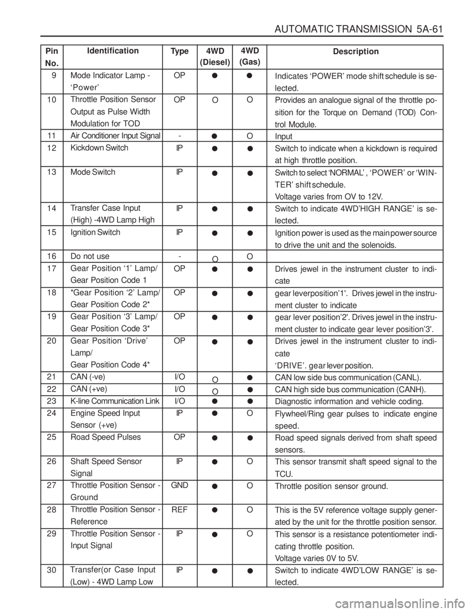
Pin
No. 9 10
11
12 13 14 1516 17 1819 20 21 22 2324 25 26 27 28 29 30Identification
Mode Indicator Lamp - ‘ Power ’
Throttle Position Sensor Output as Pulse Width Modulation for TODAir Conditioner Input SignalKickdown Switch Mode Switch
Transfer Case Input (High) -4WD Lamp High Ignition Switch Do not use Gear Position ‘1’ Lamp/
Gear Position Code 1
*Gear Position ‘2’ Lamp/
Gear Position Code 2* Gear Position ‘3’ Lamp/
Gear Position Code 3* Gear Position ‘Drive ’
Lamp/ Gear Position Code 4*CAN (-ve)CAN (+ve) K-line Communication Link Engine Speed InputSensor (+ve)Road Speed Pulses Shaft Speed Sensor SignalThrottle Position Sensor -GroundThrottle Position Sensor - Reference Throttle Position Sensor -Input Signal
Transfer(or Case Input
(Low) - 4WD Lamp Low Type
OP OP
-
IP IP IP IP
-
OPOPOP OP
I/O
I/O
I/O IP
OP
IP
GND
REF IP IP Description
Indicates ‘POWER ’ mode shift schedule is se-
lected.
Provides an analogue signal of the throttle po- sition for the T orque on Demand (T OD) Con-
trol Module. Input
Switch to indicate when a kickdown is required
at high throttle position. Switch to select ‘NORMAL ’, ‘POWER ’ or ‘WIN-
TER ’ shift schedule.
Voltage varies from OV to 12V. Switch to indicate 4WD ’HIGH RANGE ’ is se-
lected.
Ignition power is used as the main power source
to drive the unit and the solenoids.
Drives jewel in the instrument cluster to indi- cate gear leverposition ’1'. Drives jewel in the instru-
ment cluster to indicate gear lever position ’2'. Drives jewel in the instru-
ment cluster to indicate gear lever position’3'.
Drives jewel in the instrument cluster to indi- cate ‘ DRIVE ’. gear lever position.
CAN low side bus communication (CANL).
CAN high side bus communication (CANH).
Diagnostic information and vehicle coding.
Flywheel/Ring gear pulses to indicate engine speed.
Road speed signals derived from shaft speedsensors.
This sensor transmit shaft speed signal to the TCU. Throttle position sensor ground. This is the 5V reference voltage supply gener-
ated by the unit for the throttle position sensor.
This sensor is a resistance potentiometer indi-
cating throttle position.
Voltage varies 0V to 5V.Switch to indicate 4WD ’LOW RANGE ’ is se-
lected.
4WD
(Diesel)
O O O O
�
�
�
4WD
(Gas)
O O O O O O OO
�
�
�
��
��
��
��
��
��
��
��
�
��
�
�
�
�
��
�
Page 1100 of 1574

TRANSFER CASE (TOD) 5D2-11
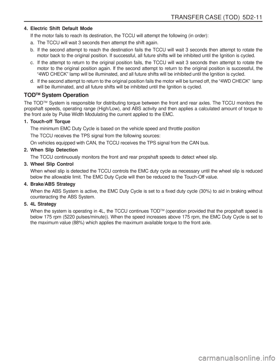
4. Electric Shift Default ModeIf the motor fails to reach its destination, the TCCU will attempt the following (in order):
a. The TCCU will wait 3 seconds then attempt the shift again.
b. If the second attempt to reach the destination fails the TCCU will wait 3 seconds then attempt to rotate the motor back to the original position. If successful, all future shifts will be inhibited until the Ignition is cycled.
c. If the attempt to return to the original position fails, the TCCU will wait 3 seconds then attempt to rotate the motor to the original position again. If the second attempt to return to the original position is successful, the “4WD CHECK ” lamp will be illuminated, and all future shifts will be inhibited until the Ignition is cycled.
d. If the second attempt to return to the original position fails the motor will be turned off, the “4WD CHECK ” lamp
will be illuminated, and all future shifts will be inhibited until the Ignition is cycled.
TOD TM
System Operation
The TOD TM
System is responsible for distributing torque between the front and rear axles. The TCCU monitors the
propshaft speeds, operating range (High/Low), and ABS activity and then applies a calculated amount of torque tothe front axle by Pulse Width Modulating the current applied to the EMC.
1. Touch-off Torque
The minimum EMC Duty Cycle is based on the vehicle speed and throttle positionThe TCCU receives the TPS signal from the following sources:On vehicles equipped with CAN, the TCCU receives the TPS signal from the CAN bus.
2. When Slip Detection
The TCCU continuously monitors the front and rear propshaft speeds to detect wheel slip.
3. Wheel Slip Control When wheel slip is detected the TCCU controls the EMC duty cycle as necessary until the wheel slip is reduced
below the allowable limit. The EMC Duty Cycle will then be reduced to the Touch-Off value.
4. Brake/ABS Strategy When the ABS System is active, the EMC Duty Cycle is set to a fixed duty cycle (30%) to aid in braking without counteracting the ABS System.
5. 4L Strategy When the system is operating in 4L, the TCCU continues TOD TM
(operation provided that the propshaft speed is
below 175 rpm (5220 pulses/minute)). When the speed increases above 175 rpm, the EMC Duty Cycle is set tothe maximum value (88%) which applies the maximum available torque to the front axle.