Page 822 of 1574
4D-2 FRONT DISC BRAKES
1 Eye-Hose Bolt...................................... 25-35 Nm
2 Gasket ................................................... Replace
3 Brake Hose
4 Brake Caliper
5 Bolt ........................................................... 20 Nm
6 Washer MAINTENANCE AND REPAIR
ON-VEHICLE SERVICE
FRONT DISC BRAKE Preceding Work : Removal of wheels and tires7 Front Disc Assembly
8 Brake Pad
9 Brake Hose and Nut ............................. 25-35 Nm
10 Gasket ................................................... Replace
11 Washer
12 Bolt .................................................... 85-105 Nm
Page 826 of 1574
SECTION 4E
REAR DISC BRAKES
TABLE OF CONTENTS
Specifications . . . . . . . . . . . . . . . . . . . . . . . . 4E-1 Fastener Tightening Specifications . . . . . . . . . 4E-1
Maintenance and Repair . . . . . . . . . . . . . . . 4E-2
On-Vehicle Service . . . . . . . . . . . . . . . . . . . . . 4E-2
SPECIFICATIONS
FASTENER TIGHTENING SPECIFICATIONS
Application
Caliper Mounting Bolt Brake HoseCaliper Bolt
N
m
85 - 105 15 - 18
20
Rear Disc Brake . . . . . . . . . . . . . . . . . . . . . . . 4E-2
Unit Repair . . . . . . . . . . . . . . . . . . . . . . . . . . . 4E-4 Rear Disc Brake . . . . . . . . . . . . . . . . . . . . . . . 4E-4
Page 827 of 1574
4E-2 REAR DISC BRAKES
1 Rear Brake Disc Assembly
2 Brake Pad
3 Brake Caliper
4 Gasket ................................................... Replace
5 Bolt........................................................... 20 Nm
6 Gasket ................................................... Replace MAINTENANCE AND REPAIR
ON-VEHICLE SERVICE
REAR DISC BRAKE Preceding Work : Removal of wheels and tires7 Brake Hose
8 Gasket ................................................... Replace
9 Eye-hose Bolt ...................................... 15-18 Nm
10 Washer
11 Bolt .................................................... 85-105 Nm
Page 830 of 1574

FrontRear
Front Rear
SECTION 4F
ANTILOCK BRAKE SYSTEM
TABLE OF CONTENTS
Caution: Disconnect the negative battery cable before removing or installing any electrical unit or when a tool or equipment could easily come in contact with exposed electrical terminals. Disconnecting thiscable will help prevent personal injury and damage to the vehicle. The ignition must also be in LOCKunless otherwise noted.
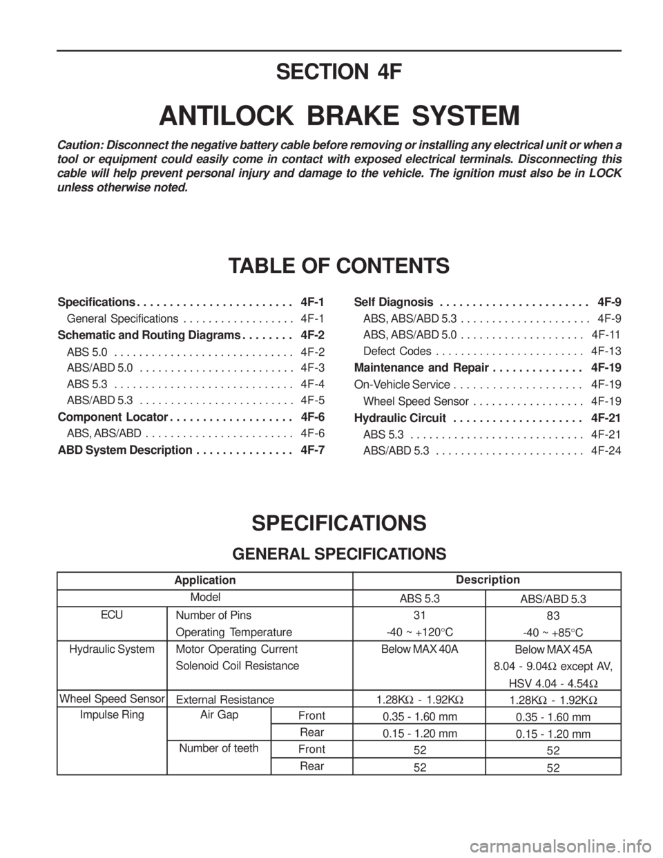
SPECIFICATIONS
GENERAL SPECIFICATIONS
Application Model
ECUNumber of Pins
Operating TemperatureMotor Operating CurrentSolenoid Coil Resistance External Resistance Air Gap
Number of teeth Description
ABS 5.3 31
-40 ~ +120 °C
Below MAX 40A
1.28K � - 1.92K �
0.35 - 1.60 mm 0.15 - 1.20 mm 52 52 ABS/ABD 5.3
83
-40 ~ +85 °C
Below MAX 45A
8.04 - 9.04 � except AV,
HSV 4.04 - 4.54 �
1.28K � - 1.92K �
0.35 - 1.60 mm 0.15 - 1.20 mm
52 52
Hydraulic System
Wheel Speed Sensor Impulse Ring
Specifications . . . . . . . . . . . . . . . . . . . . . . . . 4F-1
General Specifications . . . . . . . . . . . . . . . . . . 4F-1
Schematic and Routing Diagrams . . . . . . . . 4F-2 ABS 5.0 . . . . . . . . . . . . . . . . . . . . . . . . . . . . . 4F-2
ABS/ABD 5.0 . . . . . . . . . . . . . . . . . . . . . . . . . 4F-3
ABS 5.3 . . . . . . . . . . . . . . . . . . . . . . . . . . . . . 4F-4
ABS/ABD 5.3 . . . . . . . . . . . . . . . . . . . . . . . . . 4F-5
Component Locator . . . . . . . . . . . . . . . . . . . 4F-6 ABS, ABS/ABD . . . . . . . . . . . . . . . . . . . . . . . . 4F-6
ABD System Description . . . . . . . . . . . . . . . 4F-7 Self Diagnosis . . . . . . . . . . . . . . . . . . . . . . . 4F-9
ABS, ABS/ABD 5.3 . . . . . . . . . . . . . . . . . . . . . 4F-9
ABS, ABS/ABD 5.0 . . . . . . . . . . . . . . . . . . . . 4F-11
Defect Codes . . . . . . . . . . . . . . . . . . . . . . . . 4F-13
Maintenance and Repair . . . . . . . . . . . . . . 4F-19
On-Vehicle Service . . . . . . . . . . . . . . . . . . . . 4F-19
Wheel Speed Sensor . . . . . . . . . . . . . . . . . . 4F-19
Hydraulic Circuit . . . . . . . . . . . . . . . . . . . . 4F-21 ABS 5.3 . . . . . . . . . . . . . . . . . . . . . . . . . . . . 4F-21
ABS/ABD 5.3 . . . . . . . . . . . . . . . . . . . . . . . . 4F-24
Page 838 of 1574

ANTILOCK BRAKE SYSTEM 4F-9
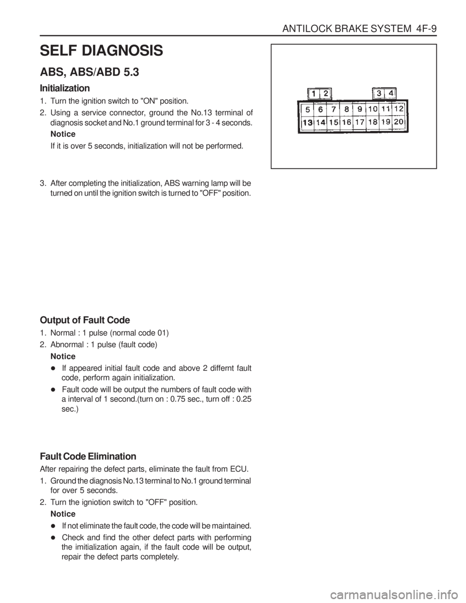
SELF DIAGNOSIS ABS, ABS/ABD 5.3 Initialization
1. Turn the ignition switch to "ON" position.
2. Using a service connector, ground the No.13 terminal ofdiagnosis socket and No.1 ground terminal for 3 - 4 seconds. Notice If it is over 5 seconds, initialization will not be performed.
3. After completing the initialization, ABS warning lamp will beturned on until the ignition switch is turned to "OFF" position.
Output of Fault Code
1. Normal : 1 pulse (normal code 01)
2. Abnormal : 1 pulse (fault code) Notice
� If appeared initial fault code and above 2 differnt fault
code, perform again initialization.
� Fault code will be output the numbers of fault code with
a interval of 1 second.(turn on : 0.75 sec., turn off : 0.25 sec.)
Fault Code Elimination After repairing the defect parts, eliminate the fault from ECU.
1. Ground the diagnosis No.13 terminal to No.1 ground terminal for over 5 seconds.
2. Turn the igniotion switch to "OFF" position. Notice
� If not eliminate the fault code, the code will be maintained.
� Check and find the other defect parts with performing
the imitialization again, if the fault code will be output,
repair the defect parts completely.
Page 840 of 1574

ANTILOCK BRAKE SYSTEM 4F-11
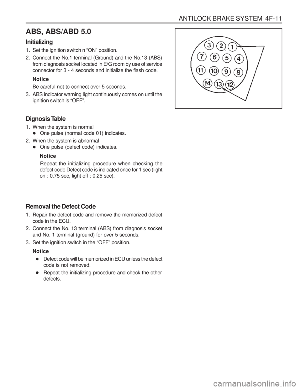
ABS, ABS/ABD 5.0 Initializing
1. Set the ignition switch n “ON ” position.
2. Connect the No.1 terminal (Ground) and the No.13 (ABS) from diagnosis socket located in E/G room by use of service connector for 3 - 4 seconds and initialize the flash code. Notice Be careful not to connect over 5 seconds.
3. ABS indicator warning light continuously comes on until the ignition switch is “OFF ”.
Dignosis Table
1. When the system is normal � One pulse (normal code 01) indicates.
2. When the system is abnormal � One pulse (defect code) indicates.
Notice Repeat the initializing procedure when checking the
defect code Defect code is indicated once for 1 sec (light on : 0.75 sec, light off : 0.25 sec).
Removal the Defect Code
1. Repair the defect code and remove the memorized defect code in the ECU.
2. Connect the No. 13 terminal (ABS) from diagnosis socket and No. 1 terminal (ground) for over 5 seconds.
3. Set the ignition switch in the “OFF ” position.
Notice � Defect code will be memorized in ECU unless the defect code is not removed.
� Repeat the initializing procedure and check the otherdefects.
Page 848 of 1574
ANTILOCK BRAKE SYSTEM 4F-19
MAINTENANCE AND REPAIRON-VEHICLE SERVICE
WHEEL SPEED SENSOR
1 Bolt
2 Front Wheel Speed Sensor
3 Knuckle 4 Bolt
5 Rear Wheel Speed Sensor
6 Rear Axle
Page 856 of 1574

SECTION 4G
PARKING BRAKE
Specifications . . . . . . . . . . . . . . . . . . . . . . . . 4G-1General Specifications . . . . . . . . . . . . . . . . . . 4G-1
Fastener Tightening Specifications . . . . . . . . . 4G-1
Component Locator . . . . . . . . . . . . . . . . . . . 4G-2 TABLE OF CONTENTS
Parking Brake . . . . . . . . . . . . . . . . . . . . . . . . . 4G-2
Maintenance and Repair . . . . . . . . . . . . . . . 4G-3
On-Vehicle Service . . . . . . . . . . . . . . . . . . . . . 4G-3 Parking Brake . . . . . . . . . . . . . . . . . . . . . . . . . 4G-3
Caution: Disconnect the negative battery cable before removing or installing any electrical unit or when a tool or equipment could easily come in contact with exposed electrical terminals. Disconnecting thiscable will help prevent personal injury and damage to the vehicle. The ignition must also be in LOCKunless otherwise noted.
SPECIFICATIONS
GENERAL SPECIFICATIONS
Application
Parking Brake Lever Bolt Cable Mounting Bracket Bolt
N
m
8 - 18 8 - 18
FASTENER TIGHTENING SPECIFICATIONS
Application
Type
Operating Type
Description
Mechanically Operated Rear Wheel Expansion Manual