2003 SSANGYONG MUSSO service
[x] Cancel search: servicePage 1153 of 1574
6E-2 STEERING WHEEL AND COLUMNMAINTENANCE AND REPAIR
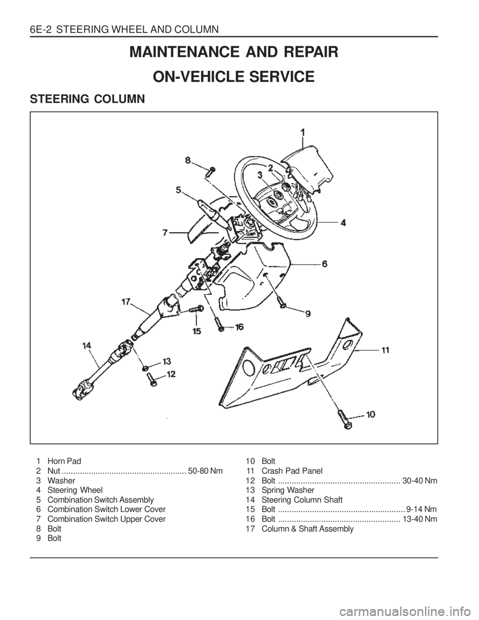
ON-VEHICLE SERVICE
STEERING COLUMN
1 Horn Pad
2 Nut ....................................................... 50-80 Nm
3 Washer
4 Steering Wheel
5 Combination Switch Assembly
6 Combination Switch Lower Cover
7 Combination Switch Upper Cover
8 Bolt
9 Bolt
10 Bolt
11 Crash Pad Panel
12 Bolt ...................................................... 30-40 Nm
13 Spring Washer
14 Steering Column Shaft
15 Bolt ........................................................ 9-14 Nm
16 Bolt ...................................................... 13-40 Nm
17 Column & Shaft Assembly
Page 1157 of 1574
SECTION 7D
FULL AUTOMATIC TEMPERATURECONTROL HEATING, VENTILATION AND AIR CONDITIONING SYSTEM
Specifications . . . . . . . . . . . . . . . . . . . . . . . . 7D-1 Specifications . . . . . . . . . . . . . . . . . . . . . . . . . 7D-1
Service Specifications . . . . . . . . . . . . . . . . . . . 7D-3
Schematic and Routing Diagrams . . . . . . . . 7D-4
Circuit Diagram . . . . . . . . . . . . . . . . . . . . . . . . 7D-4
FATC Block Diagram . . . . . . . . . . . . . . . . . . . . 7D-5
Component Locator . . . . . . . . . . . . . . . . . . . 7D-6 TABLE OF CONTENTS
Ventilation System . . . . . . . . . . . . . . . . . . . . . . 7D-6
Function Description . . . . . . . . . . . . . . . . . . . . 7D-7
Diagnosis . . . . . . . . . . . . . . . . . . . . . . . . . . . 7D-8
Diagnosis Test . . . . . . . . . . . . . . . . . . . . . . . . 7D-8
Maintenance and Repair . . . . . . . . . . . . . . 7D-11 FATC Control Panel . . . . . . . . . . . . . . . . . . . 7D-11
Troubleshooting . . . . . . . . . . . . . . . . . . . . . . 7D-15
FATC (Full Automatic Temperature Control) is full automatic heater and airconditioning system that detects incar temperature, ambient temperature, sun load and coolant temperature and controls airconditioner system
blowing capacity, outlet temperature and intaking/outlet mode to maintain interior comfort.
SPECIFICATIONSSPECIFICATIONS
Application
Core Size (LxWxT)
Core Type
Expansion Valve Type Thermostat
Resister TypeCooling Capacity Description
237.0x232.0x92.0 Aluminum plate
Angle
ON:4.5±0.6 °C, OFF:1.5±0.6 °C
Aluminum plate
4,500 Kcal/h(AT 420 CMH)
Evaporator Unit
Application
Capacity
Type Description
650-750 g R134a
Refrigerant
Page 1159 of 1574
FATC-HAVC 7D-3
SERVICE SPECIFICATIONSResistance (25 °C)
Voltage Rating Current RatingResistance (25 °C)
Voltage Rating Current Rating Resistance (25 °C)
Voltage RatingCurrent Rating
Application
Incar Sensor Ambient Sensor
Coolant Temperature Sensor
Description
Input Section
2.186k
�±0.07k �
5V
3mA
1.0k �±0.03k �
5V
3mA
0.55k �±0.02k �
5V
3mA
Current Rating (at 12V) LOCK CurrentCurrent Rating (at 12V)LOCK CurrentCurrent Rating (at 12V) LOCK Current IcPc
Application
Intake Actuator Mode Actuator Mix Actuator Power TRBlower Motor Power Consumption
Description
Output Section
70±30mA
Less than 500mA 100±40mA
Less than 500mA 100±40mA
Less than 500mA 30A
200W 220W
Page 1171 of 1574
FATC-HAVC 7D-15
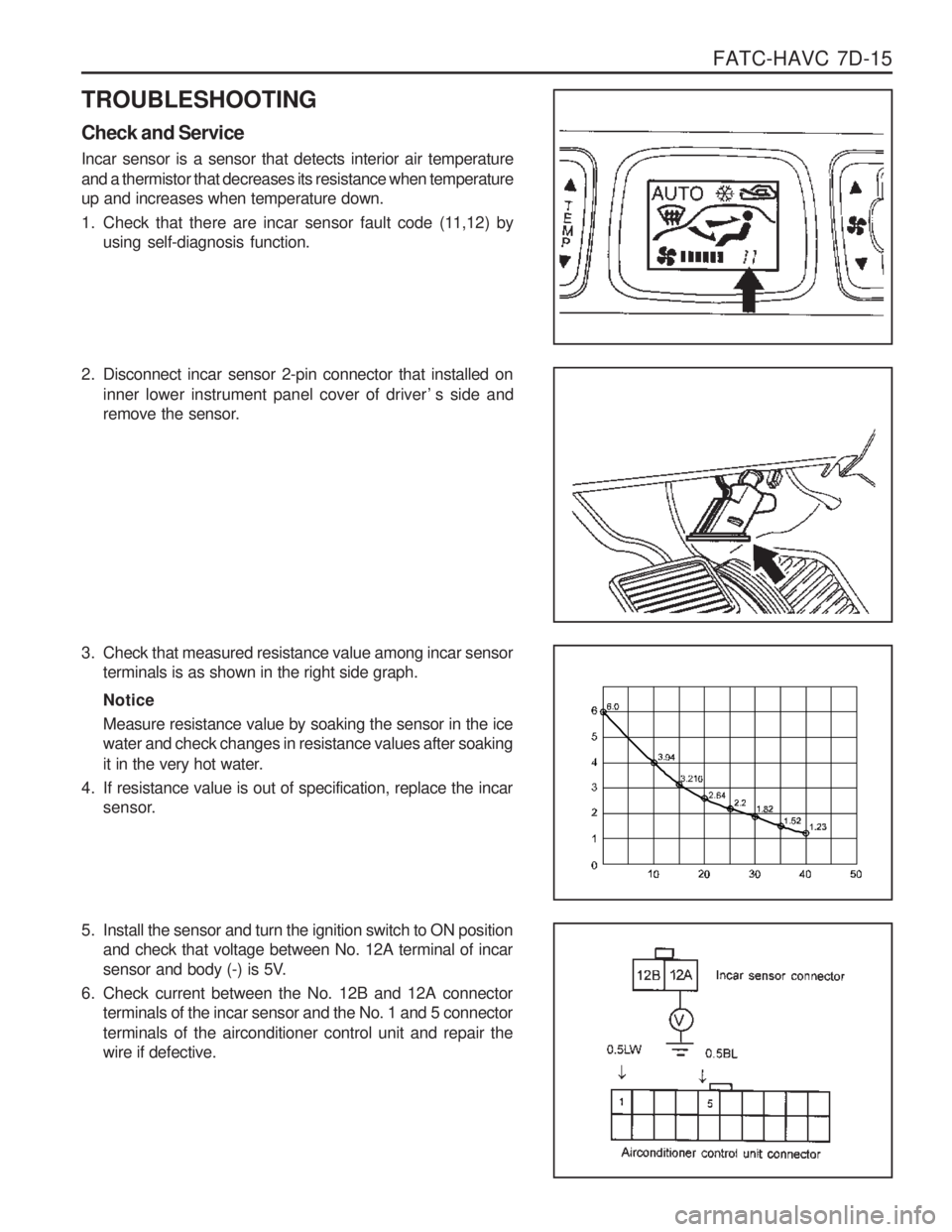
TROUBLESHOOTING Check and Service Incar sensor is a sensor that detects interior air temperature and a thermistor that decreases its resistance when temperature up and increases when temperature down.
1. Check that there are incar sensor fault code (11,12) by using self-diagnosis function.
2. Disconnect incar sensor 2-pin connector that installed on
inner lower instrument panel cover of driver ’s side and
remove the sensor.
3. Check that measured resistance value among incar sensor terminals is as shown in the right side graph. Notice Measure resistance value by soaking the sensor in the ice water and check changes in resistance values after soaking
it in the very hot water.
4. If resistance value is out of specification, replace the incar sensor.
5. Install the sensor and turn the ignition switch to ON position and check that voltage between No. 12A terminal of incar
sensor and body (-) is 5V.
6. Check current between the No. 12B and 12A connector terminals of the incar sensor and the No. 1 and 5 connector terminals of the airconditioner control unit and repair the wire if defective.
Page 1181 of 1574
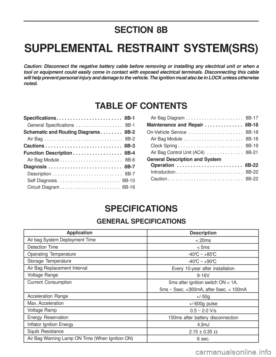
SECTION 8B
SUPPLEMENTAL RESTRAINT SYSTEM(SRS)
Specifications . . . . . . . . . . . . . . . . . . . . . . . . 8B-1General Specifications . . . . . . . . . . . . . . . . . . 8B-1
Schematic and Routing Diagrams . . . . . . . . 8B-2 Air Bag . . . . . . . . . . . . . . . . . . . . . . . . . . . . . . 8B-2
Cautions . . . . . . . . . . . . . . . . . . . . . . . . . . . . 8B-3
Function Description . . . . . . . . . . . . . . . . . . 8B-4 Air Bag Module . . . . . . . . . . . . . . . . . . . . . . . . 8B-6
Diagnosis . . . . . . . . . . . . . . . . . . . . . . . . . . . 8B-7 Description . . . . . . . . . . . . . . . . . . . . . . . . . . . 8B-7
Self Diagnosis . . . . . . . . . . . . . . . . . . . . . . . . 8B-10
Circuit Diagram . . . . . . . . . . . . . . . . . . . . . . . 8B-16
TABLE OF CONTENTS
Caution: Disconnect the negative battery cable before removing or installing any electrical unit or when a tool or equipment could easily come in contact with exposed electrical terminals. Disconnecting this cable will help prevent personal injury and damage to the vehicle. The ignition must also be in LOCK unless otherwisenoted.
SPECIFICATIONS
GENERAL SPECIFICATIONS
Application
Air bag System Deployment Time
Detection Time
Operating Temperature
Storage TemperatureAir Bag Replacement Interval
Voltage Range Current Consumption Acceleration Range Max. Acceleration
Voltage Ramp Energy Reservation Inflator Ignition EnergySquib Resistance
Air Bag Warning Lamp ON Time (When Ignition ON) Description
< 20ms< 5ms
-40°C ~ +85°C
-40°C ~ +90°C
Every 10-year after installation 9-16V
5ms after ignition switch ON < 1A,
5ms ~ 5sec. <300mA, after 5sec. < 100mA
+/-50g
+/-600g pulse 0.5 ~ 2.0 V/s
150ms after battery disconnection
4.3mJ
2.15 ± 0.35 �
6 sec.Air Bag Diagram . . . . . . . . . . . . . . . . . . . . . . 8B-17
Maintenance and Repair . . . . . . . . . . . . . . 8B-18
On-Vehicle Service . . . . . . . . . . . . . . . . . . . . . 8B-18
Air Bag Module . . . . . . . . . . . . . . . . . . . . . . . 8B-18
Clock Spring . . . . . . . . . . . . . . . . . . . . . . . . . 8B-19
Air Bag Control Unit (AC4) . . . . . . . . . . . . . . 8B-21
General Description and System Operation . . . . . . . . . . . . . . . . . . . . . . . . 8B-22
Introduction . . . . . . . . . . . . . . . . . . . . . . . . . . 8B-22
Caution . . . . . . . . . . . . . . . . . . . . . . . . . . . . . 8B-22
Page 1183 of 1574
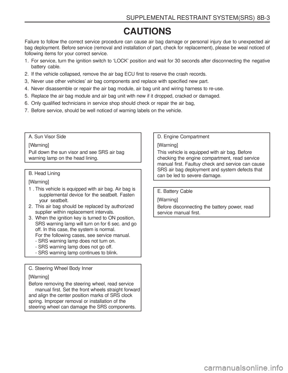
SUPPLEMENTAL RESTRAINT SYSTEM(SRS) 8B-3
CAUTIONS
Failure to follow the correct service procedure can cause air bag damage or personal injury due to unexpected air
bag deployment. Before service (removal and installation of part, check for replacement), please be weal noticed offollowing items for your correct service.
1. For service, turn the ignition switch to ‘LOCK’ position and wait for 30 seconds after disconnecting the negative battery cable.
2. If the vehicle collapsed, remove the air bag ECU first to reserve the crash records.
3, Never use other vehicles’ air bag components and replace with specified new part.
4. Never disassemble or repair the air bag module, air bag unit and wiring harness to re-use.
5. Replace the air bag module and air bag unit with new if it dropped, cracked or damaged.
6. Only qualified technicians in service shop should check or repair the air bag,
7. Before service, should be well noticed of warning labels on the vehicle.
A. Sun Visor Side
[Warning] Pull down the sun visor and see SRS air bag warning lamp on the head lining. B. Head Lining
[Warning]
1 . This vehicle is equipped with air bag. Air bag is supplemental device for the seatbelt. Fasten your seatbelt.
2. This air bag should be replaced by authorized supplier within replacement intervals.
3. When the ignition key is turned to ON position, SRS warning lamp will turn on for 6 sec. and go off. In this case, the system is normal. For the following cases, see service manual. - SRS warning lamp does not turn on. - SRS warning lamp does not go off.- SRS warning lamp continues to blink.
C. Steering Wheel Body Inner
[Warning] Before removing the steering wheel, read service manual first. Set the front wheels straight forward
and align the center position marks of SRS clock spring. Improper removal or installation of the steering wheel can damage the SRS components. D. Engine Compartment
[Warning] This vehicle is equipped with air bag. Before checking the engine compartment, read servicemanual first. Faultuy check and service can cause SRS air bag deployment and system defects that can be led to severe damage. E. Battery Cable
[Warning]
Before disconnecting the battery power, read service manual first.
Page 1191 of 1574
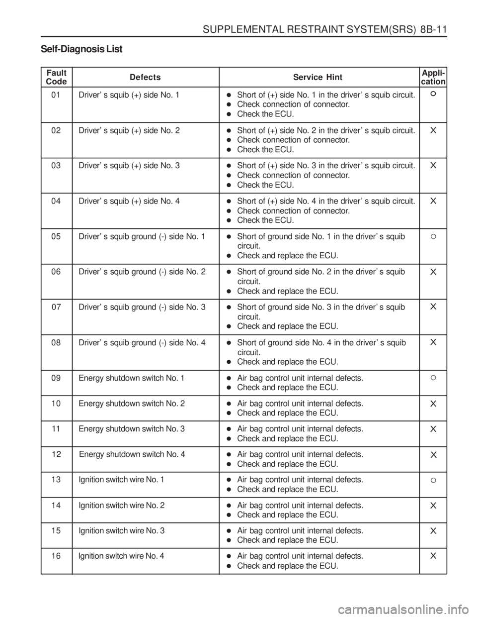
SUPPLEMENTAL RESTRAINT SYSTEM(SRS) 8B-11
Self-Diagnosis List
Fault
CodeDefects Service Hint
01 Driver’ s squib (+) side No. 1 �Short of (+) side No. 1 in the driver ’ s squib circuit.
� Check connection of connector.
� Check the ECU.Appli-
cation
02 Driver’ s squib (+) side No. 2 �Short of (+) side No. 2 in the driver ’ s squib circuit.
� Check connection of connector.
� Check the ECU.X
03 Driver’ s squib (+) side No. 3 �Short of (+) side No. 3 in the driver ’ s squib circuit.
� Check connection of connector.
� Check the ECU.X
04 Driver’ s squib (+) side No. 4 �Short of (+) side No. 4 in the driver ’ s squib circuit.
� Check connection of connector.
� Check the ECU.X
05 Driver’ s squib ground (-) side No. 1 �Short of ground side No. 1 in the driver ’ s squib
circuit.
� Check and replace the ECU.
06 Driver’ s squib ground (-) side No. 2 �Short of ground side No. 2 in the driver ’ s squib
circuit.
� Check and replace the ECU.X
07 Driver’ s squib ground (-) side No. 3 �Short of ground side No. 3 in the driver ’ s squib
circuit.
� Check and replace the ECU.X
08 Driver’ s squib ground (-) side No. 4 �Short of ground side No. 4 in the driver ’ s squib
circuit.
� Check and replace the ECU.X
09 Energy shutdown switch No. 1 �Air bag control unit internal defects.
� Check and replace the ECU.
10 Energy shutdown switch No. 2 �Air bag control unit internal defects.
� Check and replace the ECU.X
11 Energy shutdown switch No. 3 �Air bag control unit internal defects.
� Check and replace the ECU.X
12 Energy shutdown switch No. 4 �Air bag control unit internal defects.
� Check and replace the ECU.X
13 Ignition switch wire No. 1 �Air bag control unit internal defects.
� Check and replace the ECU.
14 Ignition switch wire No. 2 �Air bag control unit internal defects.
� Check and replace the ECU.X
15 Ignition switch wire No. 3 �Air bag control unit internal defects.
� Check and replace the ECU.X
16 Ignition switch wire No. 4X�Air bag control unit internal defects.
� Check and replace the ECU.
Page 1192 of 1574
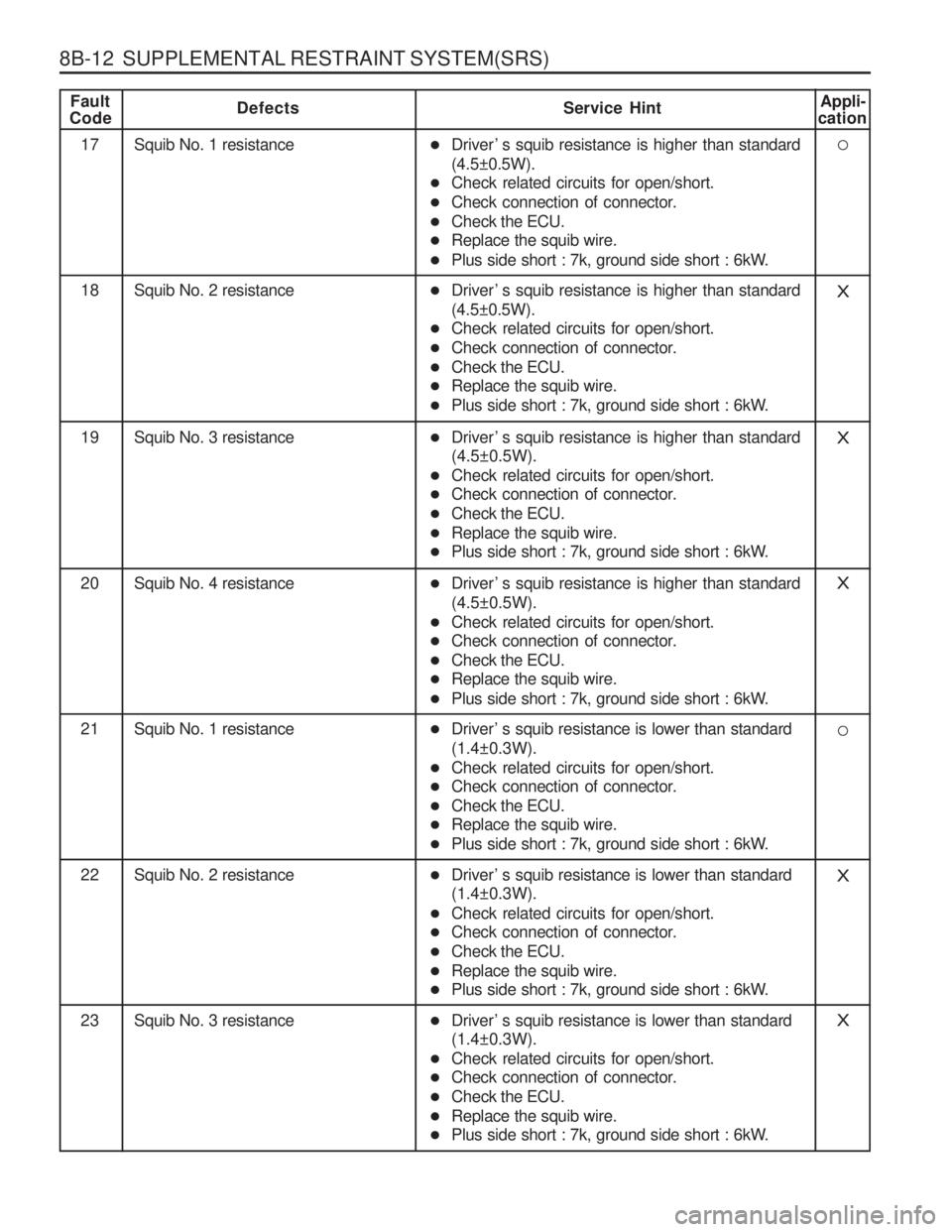
8B-12 SUPPLEMENTAL RESTRAINT SYSTEM(SRS)
Fault
CodeDefects Service HintAppli-
cation
17 Squib No. 1 resistance
18 Squib No. 2 resistanceX
19 Squib No. 3 resistanceX
20 Squib No. 4 resistanceX
21 Squib No. 1 resistance
22 Squib No. 2 resistanceX
� Driver ’ s squib resistance is higher than standard (4.5±0.5W).
� Check related circuits for open/short.
� Check connection of connector.
� Check the ECU.
� Replace the squib wire.
� Plus side short : 7k, ground side short : 6kW.
� Driver ’ s squib resistance is higher than standard(4.5±0.5W).
� Check related circuits for open/short.
� Check connection of connector.
� Check the ECU.
� Replace the squib wire.
� Plus side short : 7k, ground side short : 6kW.
� Driver ’ s squib resistance is higher than standard (4.5±0.5W).
� Check related circuits for open/short.
� Check connection of connector.
� Check the ECU.
� Replace the squib wire.
� Plus side short : 7k, ground side short : 6kW.
� Driver ’ s squib resistance is higher than standard (4.5±0.5W).
� Check related circuits for open/short.
� Check connection of connector.
� Check the ECU.
� Replace the squib wire.
� Plus side short : 7k, ground side short : 6kW.
� Driver ’ s squib resistance is lower than standard(1.4±0.3W).
� Check related circuits for open/short.
� Check connection of connector.
� Check the ECU.
� Replace the squib wire.
� Plus side short : 7k, ground side short : 6kW.
� Driver ’ s squib resistance is lower than standard (1.4±0.3W).
� Check related circuits for open/short.
� Check connection of connector.
� Check the ECU.
� Replace the squib wire.
� Plus side short : 7k, ground side short : 6kW.
23 Squib No. 3 resistanceX�Driver ’ s squib resistance is lower than standard (1.4±0.3W).
� Check related circuits for open/short.
� Check connection of connector.
� Check the ECU.
� Replace the squib wire.
� Plus side short : 7k, ground side short : 6kW.