Page 2042 of 4179

AT-6
TROUBLE DIAGNOSIS — INDEX
TROUBLE DIAGNOSIS — INDEXPFP:00000
Alphabetical & P No. Index for DTCECS003VK
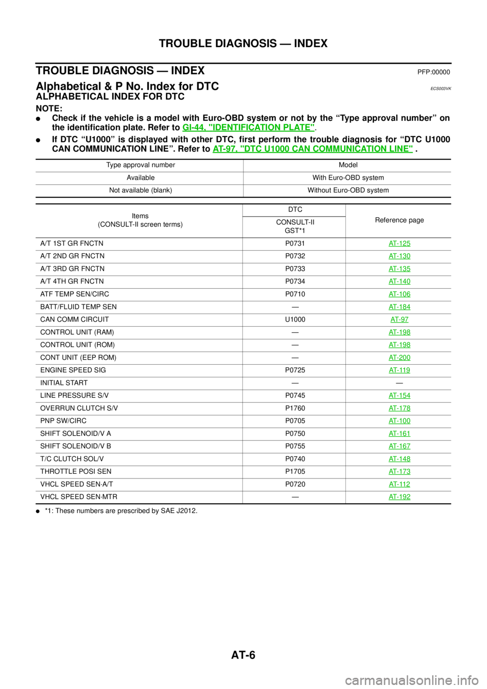
ALPHABETICAL INDEX FOR DTC
NOTE:
�Check if the vehicle is a model with Euro-OBD system or not by the “Type approval number” on
the identification plate. Refer to GI-44, "
IDENTIFICATION PLATE".
�If DTC “U1000” is displayed with other DTC, first perform the trouble diagnosis for “DTC U1000
CAN COMMUNICATION LINE”. Refer to AT- 9 7 , "
DTC U1000 CAN COMMUNICATION LINE" .
�*1: These numbers are prescribed by SAE J2012.Type approval number Model
Available With Euro-OBD system
Not available (blank) Without Euro-OBD system
Items
(CONSULT-II screen terms)DTC
Reference page
CONSULT-II
GST*1
A/T 1ST GR FNCTN P0731AT-125
A/T 2ND GR FNCTN P0732AT-130
A/T 3RD GR FNCTN P0733AT-135
A/T 4TH GR FNCTN P0734AT-140
ATF TEMP SEN/CIRC P0710AT-106
BATT/FLUID TEMP SEN —AT-184
CAN COMM CIRCUIT U1000AT- 9 7
CONTROL UNIT (RAM) —AT-198
CONTROL UNIT (ROM) —AT-198
CONT UNIT (EEP ROM) —AT-200
ENGINE SPEED SIG P0725AT- 11 9
INITIAL START — —
LINE PRESSURE S/V P0745AT-154
OVERRUN CLUTCH S/V P1760AT-178
PNP SW/CIRC P0705AT-100
SHIFT SOLENOID/V A P0750AT-161
SHIFT SOLENOID/V B P0755AT-167
T/C CLUTCH SOL/V P0740AT-148
THROTTLE POSI SEN P1705AT-173
VHCL SPEED SEN·A/T P0720AT- 11 2
VHCL SPEED SEN·MTR —AT-192
Page 2043 of 4179

TROUBLE DIAGNOSIS — INDEX
AT-7
D
E
F
G
H
I
J
K
L
MA
B
AT
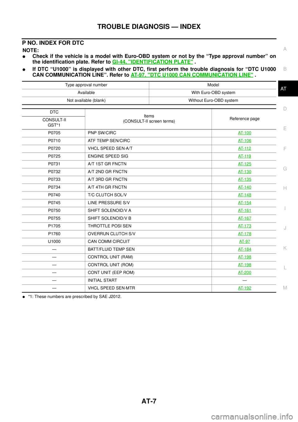
P NO. INDEX FOR DTC
NOTE:
�Check if the vehicle is a model with Euro-OBD system or not by the “Type approval number” on
the identification plate. Refer to GI-44, "
IDENTIFICATION PLATE" .
�If DTC “U1000” is displayed with other DTC, first perform the trouble diagnosis for “DTC U1000
CAN COMMUNICATION LINE”. Refer to AT- 9 7 , "
DTC U1000 CAN COMMUNICATION LINE" .
�*1: These numbers are prescribed by SAE J2012.Type approval number Model
Available With Euro-OBD system
Not available (blank) Without Euro-OBD system
DTC
Items
(CONSULT-II screen terms)Reference page
CONSULT-II
GST*1
P0705 PNP SW/CIRCAT- 1 0 0
P0710 ATF TEMP SEN/CIRCAT- 1 0 6
P0720 VHCL SPEED SEN·A/TAT- 11 2
P0725 ENGINE SPEED SIGAT- 11 9
P0731 A/T 1ST GR FNCTNAT- 1 2 5
P0732 A/T 2ND GR FNCTNAT- 1 3 0
P0733 A/T 3RD GR FNCTNAT- 1 3 5
P0734 A/T 4TH GR FNCTNAT- 1 4 0
P0740 T/C CLUTCH SOL/VAT- 1 4 8
P0745 LINE PRESSURE S/VAT- 1 5 4
P0750 SHIFT SOLENOID/V AAT- 1 6 1
P0755 SHIFT SOLENOID/V BAT- 1 6 7
P1705 THROTTLE POSI SENAT- 1 7 3
P1760 OVERRUN CLUTCH S/VAT- 1 7 8
U1000 CAN COMM CIRCUITAT- 9 7
— BATT/FLUID TEMP SENAT- 1 8 4
— CONTROL UNIT (RAM)AT- 1 9 8
— CONTROL UNIT (ROM)AT- 1 9 8
— CONT UNIT (EEP ROM)AT- 2 0 0
— INITIAL START —
— VHCL SPEED SEN·MTRAT- 1 9 2
Page 2052 of 4179

AT-16
A/T FLUID
A/T FLUIDPFP:KLE40
Checking A/T FluidECS004Q7
1. Warm up engine.
2. Check for A/T fluid leakage.
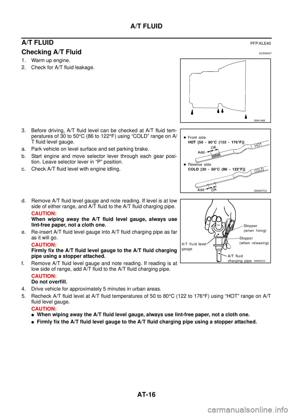
3. Before driving, A/T fluid level can be checked at A/T fluid tem-
peratures of 30 to 50°C (86 to 122°F) using “COLD” range on A/
T fluid level gauge.
a. Park vehicle on level surface and set parking brake.
b. Start engine and move selector lever through each gear posi-
tion. Leave selector lever in “P” position.
c. Check A/T fluid level with engine idling.
d. Remove A/T fluid level gauge and note reading. If level is at low
side of either range, and A/T fluid to the A/T fluid charging pipe.
CAUTION:
When wiping away the A/T fluid level gauge, always use
lint-free paper, not a cloth one.
e. Re-insert A/T fluid level gauge into A/T fluid charging pipe as far
as it will go.
CAUTION:
Firmly fix the A/T fluid level gauge to the A/T fluid charging
pipe using a stopper attached.
f. Remove A/T fluid level gauge and note reading. If reading is at
low side of range, add A/T fluid to the A/T fluid charging pipe.
CAUTION:
Do not overfill.
4. Drive vehicle for approximately 5 minutes in urban areas.
5. Recheck A/T fluid level at A/T fluid temperatures of 50 to 80°C (122 to 176°F) using “HOT” range on A/T
fluid level gauge.
CAUTION:
�When wiping away the A/T fluid level gauge, always use lint-free paper, not a cloth one.
�Firmly fix the A/T fluid level gauge to the A/T fluid charging pipe using a stopper attached.
SMA146B
SMA827CA
SMA051D
Page 2070 of 4179

AT-34
OVERALL SYSTEM
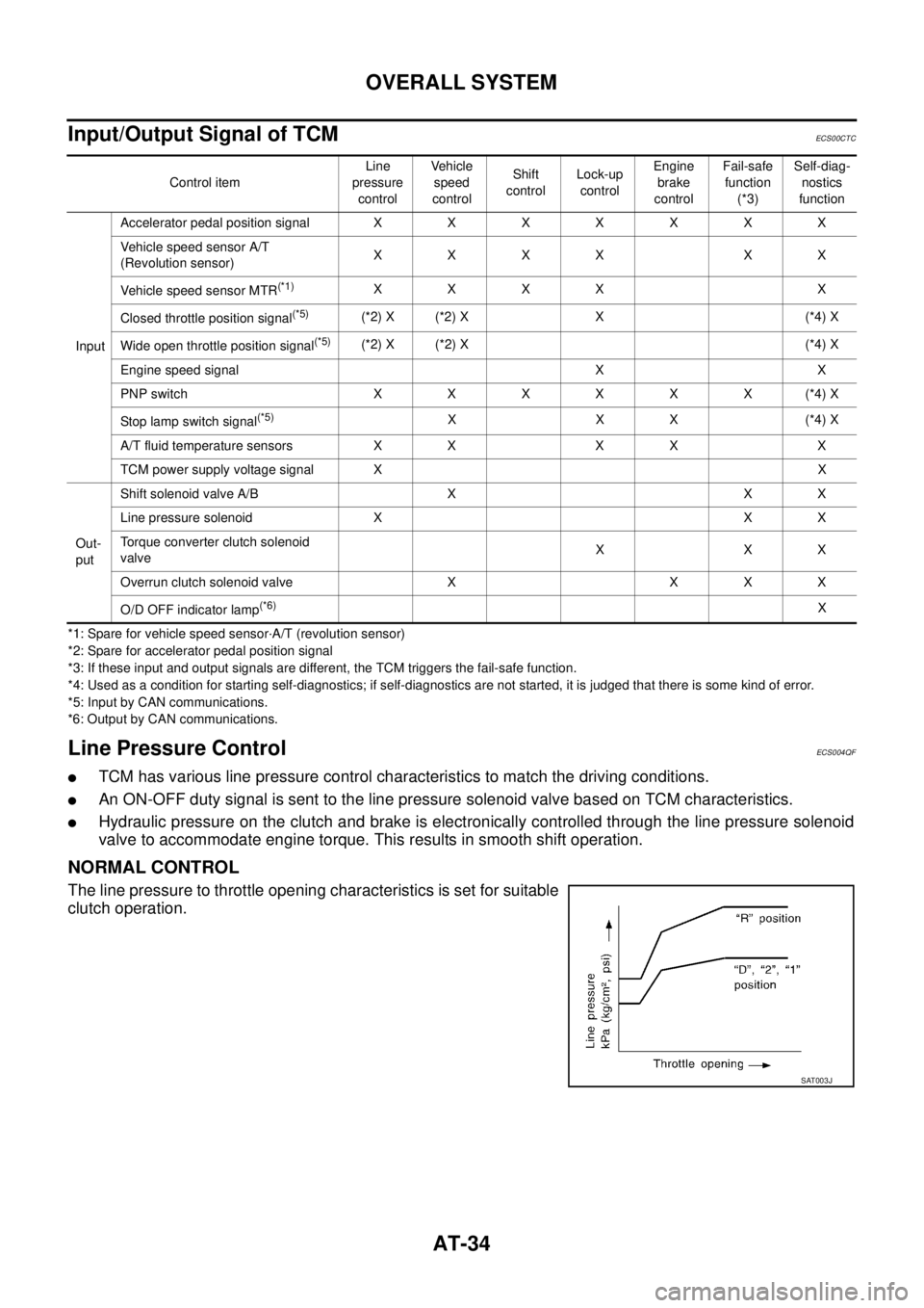
Input/Output Signal of TCMECS00CTC
*1: Spare for vehicle speed sensor·A/T (revolution sensor)
*2: Spare for accelerator pedal position signal
*3: If these input and output signals are different, the TCM triggers the fail-safe function.
*4: Used as a condition for starting self-diagnostics; if self-diagnostics are not started, it is judged that there is some kind of error.
*5: Input by CAN communications.
*6: Output by CAN communications.
Line Pressure ControlECS004QF
�TCM has various line pressure control characteristics to match the driving conditions.
�An ON-OFF duty signal is sent to the line pressure solenoid valve based on TCM characteristics.
�Hydraulic pressure on the clutch and brake is electronically controlled through the line pressure solenoid
valve to accommodate engine torque. This results in smooth shift operation.
NORMAL CONTROL
The line pressure to throttle opening characteristics is set for suitable
clutch operation.
Control itemLine
pressure
controlVehicle
speed
controlShift
controlLock-up
controlEngine
brake
controlFail-safe
function
(*3)Self-diag-
nostics
function
InputAccelerator pedal position signalXXXXXXX
Vehicle speed sensor A/T
(Revolution sensor)XXXX XX
Vehicle speed sensor MTR
(*1)XXXX X
Closed throttle position signal
(*5)(*2) X (*2) X X (*4) X
Wide open throttle position signal
(*5)(*2) X (*2) X (*4) X
Engine speed signal X X
PNP switch XXXXXX(*4) X
Stop lamp switch signal
(*5)XXX(*4) X
A/T fluid temperature sensors X X X X X
TCM power supply voltage signal XX
Out-
putShift solenoid valve A/B X X X
Line pressure solenoid X X X
Torque converter clutch solenoid
valveXXX
Overrun clutch solenoid valve X X X X
O/D OFF indicator lamp
(*6)X
SAT003J
Page 2080 of 4179
![NISSAN X-TRAIL 2003 Service Repair Manual AT-44
[EURO-OBD]
ON BOARD DIAGNOSTIC SYSTEM DESCRIPTION
Malfunction Indicator lamp (MIL)ECS004QL
1. The malfunction indicator lamp will light up when the ignition
switch is turned ON without the eng NISSAN X-TRAIL 2003 Service Repair Manual AT-44
[EURO-OBD]
ON BOARD DIAGNOSTIC SYSTEM DESCRIPTION
Malfunction Indicator lamp (MIL)ECS004QL
1. The malfunction indicator lamp will light up when the ignition
switch is turned ON without the eng](/manual-img/5/57404/w960_57404-2079.png)
AT-44
[EURO-OBD]
ON BOARD DIAGNOSTIC SYSTEM DESCRIPTION
Malfunction Indicator lamp (MIL)ECS004QL
1. The malfunction indicator lamp will light up when the ignition
switch is turned ON without the engine running. This is for
checking the lamp.
�If the malfunction indicator does not light up, refer to DI-33,
"Schematic" .
(Or see MIL & CONSULT-II in EC section. Refer to EC-64,
"Malfunction Indicator (MI)" (WITH EURO-OBD) or EC-516,
"Malfunction Indicator (MI)" (WITHOUT EURO-OBD) or EC-
102, "CONSULT-II Function" (WITH EURO-OBD) or EC-551,
"CONSULT-II Function" (WITHOUT EURO-OBD).
2. When the engine is started, the malfunction indicator should go
off.
If the lamp remains on, the on board diagnostic system has detected an emission-related (EURO-OBD)
malfunction. For detail, refer to EC-51, "
ON BOARD DIAGNOSTIC (OBD) SYSTEM" .
CONSULT-IIECS004QM
After performing “SELF-DIAGNOSTIC PROCEDURE (WITH CONSULT-II)” AT- 4 5 , place check marks for
results on the “DIAGNOSTIC WORKSHEET”, AT- 5 8
. Reference pages are provided following the items.
NOTICE:
1. The CONSULT-II electrically displays shift timing and lock-up timing (that is, operation timing of each sole-
noid).
Check for time difference between actual shift timing and the CONSULT-II display. If the difference is
noticeable, mechanical parts (except solenoids, sensors, etc.) may be malfunctioning. Check mechanical
parts using applicable diagnostic procedures.
2. Shift schedule (which implies gear position) displayed on CONSULT-II and that indicated in Service Man-
ual may differ slightly. This occurs because of the following reasons:
–Actual shift schedule has more or less tolerance or allowance,
–Shift schedule indicated in Service Manual refers to the point where shifts start, and
–Gear position displayed on CONSULT-II indicates the point where shifts are completed.
3. Shift solenoid valve “A” or “B” is displayed on CONSULT-II at the start of shifting. Gear position is dis-
played upon completion of shifting (which is computed by TCM).
4. Additional CONSULT-II information can be found in the Operation Manual supplied with the CONSULT-II
unit.
FUNCTION
SAT652J
Diagnostic test mode Function Reference page
Work supportThis mode enables a technician to adjust some devices faster and more accurately by
following the indications on CONSULT-II.—
Self-diagnostic results Self-diagnostic results can be read and erased quickly.AT- 4 5
Data monitor Input/Output data in the ECM can be read.AT- 4 6
CAN diagnostic support
monitorThe results of transmit/receive diagnosis of CAN communication can be read. —
Function testConducted by CONSULT-II instead of a technician to determine whether each system
is “OK” or “NG”.—
DTC work support Select the operating condition to confirm Diagnosis Trouble Codes.AT- 4 7
TCM part number TCM part number can be read. —
Page 2082 of 4179
![NISSAN X-TRAIL 2003 Service Repair Manual AT-46
[EURO-OBD]
ON BOARD DIAGNOSTIC SYSTEM DESCRIPTION
*1: These malfunctions cannot be displayed by MIL if another malfunction is assigned to lamp MIL.
DATA MONITOR MODE (A/T)
X: Standard, —: N NISSAN X-TRAIL 2003 Service Repair Manual AT-46
[EURO-OBD]
ON BOARD DIAGNOSTIC SYSTEM DESCRIPTION
*1: These malfunctions cannot be displayed by MIL if another malfunction is assigned to lamp MIL.
DATA MONITOR MODE (A/T)
X: Standard, —: N](/manual-img/5/57404/w960_57404-2081.png)
AT-46
[EURO-OBD]
ON BOARD DIAGNOSTIC SYSTEM DESCRIPTION
*1: These malfunctions cannot be displayed by MIL if another malfunction is assigned to lamp MIL.
DATA MONITOR MODE (A/T)
X: Standard, —: Not applicable, : Option CONT UNIT(EEP ROM)
�TCM memory (EEP ROM) is malfunctioning. —
PNP SW/CIRC
�TCM does not receive the correct voltage signal (based on the gear
position) from the switch.P0705
INITIAL START
�This is not a malfunction message (Whenever shutting off a power sup-
ply to the TCM, this message appears on the screen).—
No failure
(NO SELF DIAGNOSTIC FAILURE
INDICATED FURTHER TESTING
MAY BE REQUIRED)
�No failure has been detected. — Items (CONSULT-II screen terms) Malfunction is detected when... EURO-OBD (DTC)
Monitor item (Unit)SELECT MONITOR ITEM
Remarks
TCM INPUT
SIGNALSMAIN SIG-
NALSSELEC-
TION FROM
MENU
VHCL/S SE·A/T (km/h) X — Revolution sensor
VHCL/S SE·MTR (km/h) X —Vehicle speed display may not be accu-
rate under approx. 10 km/h (6 mph). It
may not indicate 0 km/h (0 mph) when
vehicle is stationary.
THRTL POS SEN (V) X —
FLUID TEMP SE (V) X —
BATTERY VOLT (V) X —
ENGINE SPEED (rpm) X X
TURBINE REV (rpm) X —
OVERDRIVE SW (ON/OFF) X —
PN POSI SW (ON/OFF) X —
R POSITION SW (ON/OFF) X —
D POSITION SW (ON/OFF) X —
2 POSITION SW (ON/OFF) X —
1 POSITION SW (ON/OFF) X —
ASCD·CRUISE (ON/OFF) X —
Signal input with CAN communication.
ACC OD CUT (ON/OFF) X —
KICKDOWN SW (ON/OFF) X —
Not mounted but displayed.
POWERSHIFT SW (ON/OFF) X —
CLOSED THL/SW (ON/OFF) X —
Signal input with CAN communication.
W/O THRL/P-SW (ON/OFF) X —
*SHIFT S/V A (ON/OFF) — —
Displays status of check signal (reinput
signal) for TCM control signal output.
Remains unchanged when solenoid
valves are open or shorted. *SHIFT S/V B (ON/OFF) — —
*OVERRUN/C S/V (ON/OFF) — —
HOLD SW (ON/OFF) X — Not mounted but displayed.
BRAKE SW (ON/OFF) X — Stop lamp switch
Page 2084 of 4179
AT-48
[EURO-OBD]
ON BOARD DIAGNOSTIC SYSTEM DESCRIPTION
3. Turn ignition switch “ON”. (Do not start engine.)
4. Touch “START (NISSAN BASED VHCL)”.
5. Touch “A/T”.
If “A/T” is not indicated, go to GI-35, "
CONSULT-II Data Link
Connector (DLC) Circuit" .
6. Touch “DTC WORK SUPPORT”.
7. Touch select item menu (1ST, 2ND, etc.).
SCIA0692E
SAIA0450E
SAT014K
SCIA5358E
SAT018K
Page 2085 of 4179
ON BOARD DIAGNOSTIC SYSTEM DESCRIPTION
AT-49
[EURO-OBD]
D
E
F
G
H
I
J
K
L
MA
B
AT
8. Touch “START”.
9. Perform driving test according to “DTC Confirmation Procedure”
in “TROUBLE DIAGNOSIS FOR DTC”.
�When testing conditions are satisfied, CONSULT-II screen
changes from “OUT OF CONDITION” to “TESTING”.
10. Stop vehicle.
SAT589J
SAT019K
SAT591J
SAT592J