Page 1864 of 4179
EC-1486
[YD (WITHOUT EURO-OBD)]
PSP SWITCH
5. CHECK POWER STEERING PRESSURE SWITCH
Refer to EC-1486, "
Component Inspection" .
OK or NG
OK >> GO TO 6.
NG >> Replace power steering pressure switch.
6. CHECK INTERMITTENT INCIDENT
Refer to EC-1260, "
TROUBLE DIAGNOSIS FOR INTERMITTENT INCIDENT" .
>>INSPECTION END
Component InspectionEBS0126F
POWER STEERING PRESSURE SWITCH
1. Disconnect power steering pressure switch harness connector and then start engine.
2. Check continuity between power steering pressure switch termi-
nal 1 and 2 under the following conditions.
Removal and InstallationEBS0128A
Refer to PS-34, "HYDRAULIC LINE" .
Conditions Continuity
Steering wheel is being fully turned. Yes
Steering wheel is not being turned. No
MBIB0624E
Page 1874 of 4179
EC-1496
[YD (WITHOUT EURO-OBD)]
START SIGNAL
START SIGNALPFP:48750
Wiring DiagramEBS0126M
TBWA0582E
Page 1875 of 4179
![NISSAN X-TRAIL 2003 Service Repair Manual START SIGNAL
EC-1497
[YD (WITHOUT EURO-OBD)]
C
D
E
F
G
H
I
J
K
L
MA
EC
Diagnostic ProcedureEBS0126N
1. CHECK START SIGNAL OVERALL FUNCTION
With CONSULT-II
1. Turn ignition switch ON.
2. Check “ST](/manual-img/5/57404/w960_57404-1874.png "NISSAN X-TRAIL 2003 Service Repair Manual START SIGNAL
EC-1497
[YD (WITHOUT EURO-OBD)]
C
D
E
F
G
H
I
J
K
L
MA
EC
Diagnostic ProcedureEBS0126N
1. CHECK START SIGNAL OVERALL FUNCTION
With CONSULT-II
1. Turn ignition switch ON.
2. Check “ST")
START SIGNAL
EC-1497
[YD (WITHOUT EURO-OBD)]
C
D
E
F
G
H
I
J
K
L
MA
EC
Diagnostic ProcedureEBS0126N
1. CHECK START SIGNAL OVERALL FUNCTION
With CONSULT-II
1. Turn ignition switch ON.
2. Check “START SIGNAL” in “DATA MONITOR” mode with CON-
SULT-II under the following conditions.
OK or NG
OK >>INSPECTION END
NG >> GO TO 2.
2. CHECK START SIGNAL INPUT SIGNAL CIRCUIT
1. Turn ignition switch OFF.
2. Disconnect ECM harness connector and ignition switch harness connector.
3. Check harness continuity between ECM terminal 99 and ignition switch terminal 6.
Refer to Wiring Diagram.
4. Also check harness for short to ground and short to power.
OK or NG
OK >> GO TO 4.
NG >> GO TO 3.
3. DETECT MALFUNCTIONING PART
Check the following.
�10A fuse
�Fuse block (J/B) connectors M1, E102
�Harness for open or short between ECM and ignition switch
>> Repair open circuit or short to ground or short to power in harness or connectors.
4. CHECK INTERMITTENT INCIDENT
Refer to EC-1260, "
TROUBLE DIAGNOSIS FOR INTERMITTENT INCIDENT" .
>>INSPECTION END
Condition START SIGNAL
Ignition switch ON OFF
Ignition switch START ON
PBIB0433E
Continuity should exist.
Page 1881 of 4179
![NISSAN X-TRAIL 2003 Service Repair Manual FUEL SYSTEM
FL-3
[QR]
C
D
E
F
G
H
I
J
K
L
MA
FL
FUEL SYSTEMPFP:17503
Checking Fuel LinesEBS00KOS
Inspect fuel lines, filler cap and tank for improper attachment, leaks,
cracks, damage, loose connect](/manual-img/5/57404/w960_57404-1880.png "NISSAN X-TRAIL 2003 Service Repair Manual FUEL SYSTEM
FL-3
[QR]
C
D
E
F
G
H
I
J
K
L
MA
FL
FUEL SYSTEMPFP:17503
Checking Fuel LinesEBS00KOS
Inspect fuel lines, filler cap and tank for improper attachment, leaks,
cracks, damage, loose connect")
FUEL SYSTEM
FL-3
[QR]
C
D
E
F
G
H
I
J
K
L
MA
FL
FUEL SYSTEMPFP:17503
Checking Fuel LinesEBS00KOS
Inspect fuel lines, filler cap and tank for improper attachment, leaks,
cracks, damage, loose connections, chafing or deterioration.
If necessary, repair or replace damaged parts.
General PrecautionsEBS011T7
WARNING:
When replacing fuel line parts, be sure to observe the following.
�Put a “CAUTION: INFLAMMABLE” sign in the workshop.
�Be sure to work in a well ventilated area and furnish workshop with a CO2 fire extinguisher.
�Do not smoke while servicing fuel system. Keep open flames and sparks away from the work area.
CAUTION:
�Before removing fuel line parts, perform the following procedures:
–Put drained fuel in an explosion-proof container and put the lid on securely. Keep the container in
safe area.
–Release fuel pressure from the fuel lines. Refer to EC-48, "FUEL PRESSURE RELEASE" (WITH
EURO-OBD) or EC-510, "
FUEL PRESSURE RELEASE" (WITHOUT EURO-OBD).
–Disconnect negative battery terminal.
�Always replace O-rings and clamps with new ones.
�Do not kink or twist tubes when they are being installed.
�Do not tighten hose clamps excessively to avoid damaging hoses.
�After connecting fuel tube quick connectors, make sure
quick connectors are secure.
Ensure that connector and resin tube do not contact any
adjacent parts.
�After installing tubes, check if there are no fuel leaks at con-
nections in the following steps.
–Apply fuel pressure to fuel lines with turning ignition switch
“ON” (with engine stopped). Then check for fuel leaks at
connections.
–Start engine and rev it up and check for fuel leaks at con-
nections.
�For servicing “Evaporative Emission System” parts, refer to
EC-473, "
EVAPORATIVE EMISSION SYSTEM" (WITH EURO-
ODB) or EC-865, "
EVAPORATIVE EMISSION SYSTEM"
(WITHOUT EURO-OBD).
SMA803A
SBIA0504E
Page 1883 of 4179
FUEL LEVEL SENSOR UNIT, FUEL FILTER AND FUEL PUMP ASSEMBLY
FL-5
[QR]
C
D
E
F
G
H
I
J
K
L
MA
FL
6. Remove inspection hole cover for main and sub fuel level sen-
sor units by turning clips clockwise by 90 degrees.
7. Disconnect harness connector and fuel feed hose.
�Disconnect quick connector as follows:
–Hold the sides of connector, push in tabs and pull out tube.
–If connector and tube are stuck together, push and pull sev-
eral times until they start to move. Then disconnect them by
pulling.
PBIC2258E
KBIA0280E
SFE562A
Page 1886 of 4179
FL-8
[QR]
FUEL LEVEL SENSOR UNIT, FUEL FILTER AND FUEL PUMP ASSEMBLY
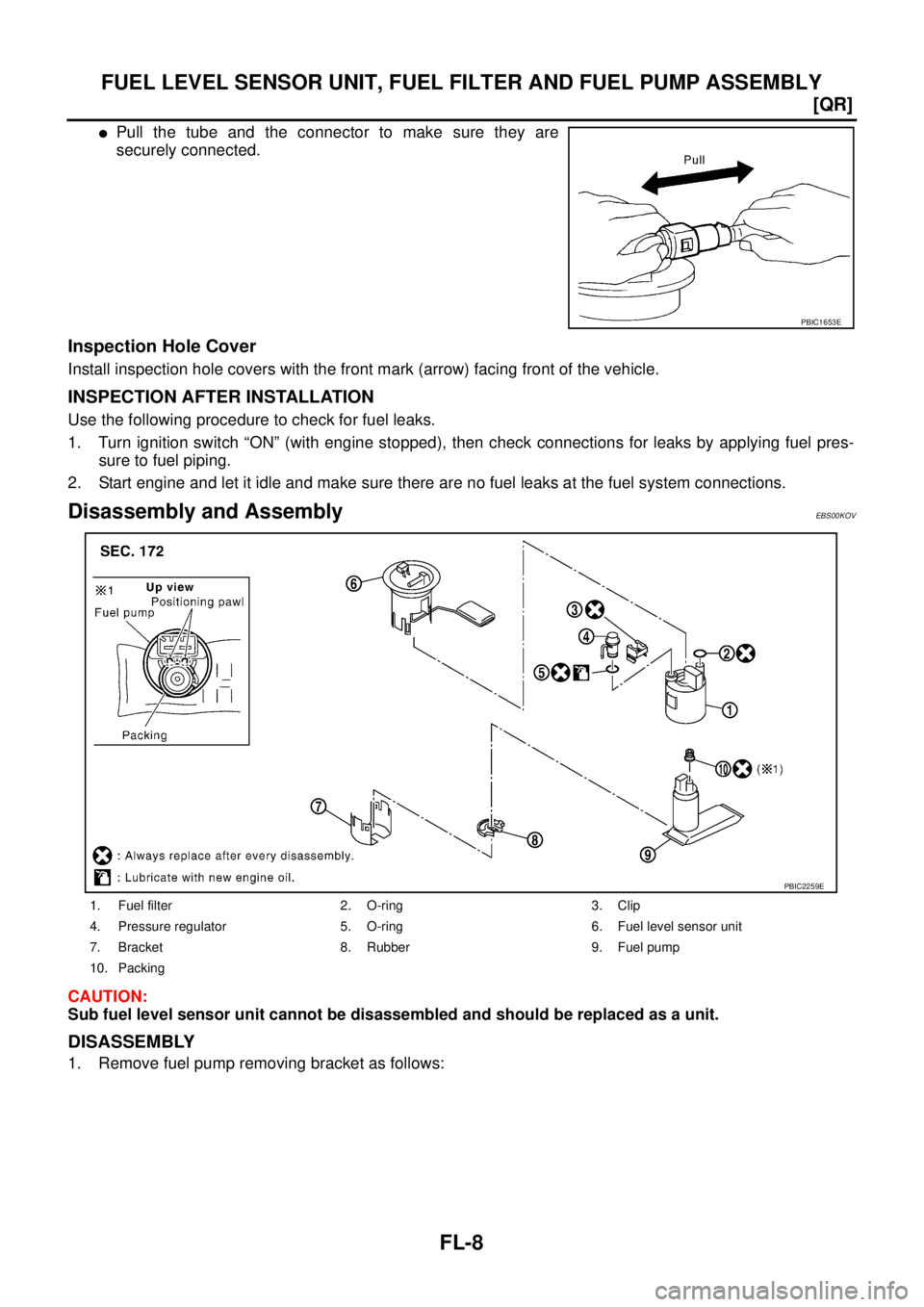
�Pull the tube and the connector to make sure they are
securely connected.
Inspection Hole Cover
Install inspection hole covers with the front mark (arrow) facing front of the vehicle.
INSPECTION AFTER INSTALLATION
Use the following procedure to check for fuel leaks.
1. Turn ignition switch “ON” (with engine stopped), then check connections for leaks by applying fuel pres-
sure to fuel piping.
2. Start engine and let it idle and make sure there are no fuel leaks at the fuel system connections.
Disassembly and AssemblyEBS00KOV
CAUTION:
Sub fuel level sensor unit cannot be disassembled and should be replaced as a unit.
DISASSEMBLY
1. Remove fuel pump removing bracket as follows:
PBIC1653E
1. Fuel filter 2. O-ring 3. Clip
4. Pressure regulator 5. O-ring 6. Fuel level sensor unit
7. Bracket 8. Rubber 9. Fuel pump
10. Packing
PBIC2259E
Page 1891 of 4179
FUEL TANK
FL-13
[QR]
C
D
E
F
G
H
I
J
K
L
MA
FL
CAUTION:
Use genuine fuel filler tube mounting bolts or equivalent. Make sure to tighten them to the speci-
fied torque.
�To connect quick connector, refer to FL-7, "Quick Connector" .
INSPECTION AFTER INSTALLATION
Use the following procedure to check for fuel leaks.
1. Turn ignition switch “ON” (with engine stopped), and check connections for leaks by applying fuel pres-
sure to fuel piping.
2. Start engine and let it idle and make sure there are no fuel leaks at the fuel system tube and hose connec-
tions.
Page 1894 of 4179
![NISSAN X-TRAIL 2003 Service Repair Manual FL-16
[YD22DDTi]
FUEL SYSTEM
FUEL SYSTEMPFP:17503
Checking Fuel LinesEBS00BKH
Inspect fuel lines, filler cap and tank for improper attachment, leaks,
cracks, damage, loose connections, chafing or de](/manual-img/5/57404/w960_57404-1893.png "NISSAN X-TRAIL 2003 Service Repair Manual FL-16
[YD22DDTi]
FUEL SYSTEM
FUEL SYSTEMPFP:17503
Checking Fuel LinesEBS00BKH
Inspect fuel lines, filler cap and tank for improper attachment, leaks,
cracks, damage, loose connections, chafing or de")
FL-16
[YD22DDTi]
FUEL SYSTEM
FUEL SYSTEMPFP:17503
Checking Fuel LinesEBS00BKH
Inspect fuel lines, filler cap and tank for improper attachment, leaks,
cracks, damage, loose connections, chafing or deterioration.
If necessary, repair or replace damaged parts.
General PrecautionsEBS00BKI
WARNING:
When replacing fuel line parts, be sure to observe the following.
�Put a “CAUTION: INFLAMMABLE” sign in workshop.
�Be sure to work in a well-ventilated area and furnish workshop with a CO2 fire extinguisher.
�Do not smoke while servicing fuel system. Keep open flames and spark away from work area.
CAUTION:
�Before removing fuel line parts, perform the following procedures:
–Put drained fuel in an explosion-proof container and put the lid on securely. Keep the container in
safe area.
–Disconnect negative battery terminal.
�Always replace O-ring and clamps with new ones.
�Do not kink or twist tubes when they are being installed.
�Do not tighten hose clamps excessively to avoid damaging hoses.
�After connecting fuel tube quick connectors, make sure
quick connectors are secure.
Ensure that connector and resin tube do not contact any
adjacent parts.
�After installing tubes, make sure there is no fuel leakage at
connections in the following steps.
–Start the engine and rev it up and check for fuel leaks at
connections.
SMA803A
SBIA0504E
![NISSAN X-TRAIL 2003 Service Repair Manual EC-1486
[YD (WITHOUT EURO-OBD)]
PSP SWITCH
5. CHECK POWER STEERING PRESSURE SWITCH
Refer to EC-1486, "
Component Inspection" .
OK or NG
OK >> GO TO 6.
NG >> Replace power steering pressure switch.
6](/manual-img/5/57404/w960_57404-1863.png "NISSAN X-TRAIL 2003 Service Repair Manual EC-1486
[YD (WITHOUT EURO-OBD)]
PSP SWITCH
5. CHECK POWER STEERING PRESSURE SWITCH
Refer to EC-1486, \"
Component Inspection\" .
OK or NG
OK >> GO TO 6.
NG >> Replace power steering pressure switch.
6")
![NISSAN X-TRAIL 2003 Service Repair Manual EC-1496
[YD (WITHOUT EURO-OBD)]
START SIGNAL
START SIGNALPFP:48750
Wiring DiagramEBS0126M
TBWA0582E](/manual-img/5/57404/w960_57404-1873.png "NISSAN X-TRAIL 2003 Service Repair Manual EC-1496
[YD (WITHOUT EURO-OBD)]
START SIGNAL
START SIGNALPFP:48750
Wiring DiagramEBS0126M
TBWA0582E")
![NISSAN X-TRAIL 2003 Service Repair Manual FUEL LEVEL SENSOR UNIT, FUEL FILTER AND FUEL PUMP ASSEMBLY
FL-5
[QR]
C
D
E
F
G
H
I
J
K
L
MA
FL
6. Remove inspection hole cover for main and sub fuel level sen-
sor units by turning clips clockwise b](/manual-img/5/57404/w960_57404-1882.png "NISSAN X-TRAIL 2003 Service Repair Manual FUEL LEVEL SENSOR UNIT, FUEL FILTER AND FUEL PUMP ASSEMBLY
FL-5
[QR]
C
D
E
F
G
H
I
J
K
L
MA
FL
6. Remove inspection hole cover for main and sub fuel level sen-
sor units by turning clips clockwise b")