Page 273 of 4179
CYLINDER BLOCK
EM-221
[YD22DDTi]
C
D
E
F
G
H
I
J
K
L
MA
EM
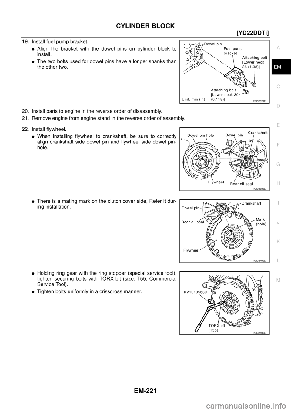
19. Install fuel pump bracket.
�Align the bracket with the dowel pins on cylinder block to
install.
�The two bolts used for dowel pins have a longer shanks than
the other two.
20. Install parts to engine in the reverse order of disassembly.
21. Remove engine from engine stand in the reverse order of assembly.
22. Install flywheel.
�When installing flywheel to crankshaft, be sure to correctly
align crankshaft side dowel pin and flywheel side dowel pin-
hole.
�There is a mating mark on the clutch cover side, Refer it dur-
ing installation.
�Holding ring gear with the ring stopper (special service tool),
tighten securing bolts with TORX bit (size: T55, Commercial
Service Tool).
�Tighten bolts uniformly in a crisscross manner.
PBIC2329E
PBIC2538E
PBIC2495E
PBIC2406E
Page 287 of 4179
![NISSAN X-TRAIL 2003 Service Repair Manual CYLINDER BLOCK
EM-235
[YD22DDTi]
C
D
E
F
G
H
I
J
K
L
MA
EM
FLYWHEEL DEFLECTION
�Measure the deflection of flywheel contact surface to clutch with
a dial indicator.
�Measure the deflection at 210 mm](/manual-img/5/57404/w960_57404-286.png "NISSAN X-TRAIL 2003 Service Repair Manual CYLINDER BLOCK
EM-235
[YD22DDTi]
C
D
E
F
G
H
I
J
K
L
MA
EM
FLYWHEEL DEFLECTION
�Measure the deflection of flywheel contact surface to clutch with
a dial indicator.
�Measure the deflection at 210 mm")
CYLINDER BLOCK
EM-235
[YD22DDTi]
C
D
E
F
G
H
I
J
K
L
MA
EM
FLYWHEEL DEFLECTION
�Measure the deflection of flywheel contact surface to clutch with
a dial indicator.
�Measure the deflection at 210 mm (8.27 in) dia.
�If measured value is out of the standard, replace flywheel.
CAUTION:
When measuring, keep magnetic fields (such as dial indicator
stand) away from signal plate of the rear end of crankshaft.
MOVEMENT AMOUNT OF FLYWHEEL
CAUTION:
Do not disassemble double mass flywheel.
Movement Amount of Thrust (Fore-and-Aft) Direction
�Measure the movement amount of thrust (fore-and-aft) direction when 100 N (10.2 kg, 22 lb) force is
added at the portion of 125 mm (4.92 in) radius from the center of flywheel.
�If measured value is out of the standard, replace flywheel.
Movement Amount in Radial (Rotation) Direction
Check the movement amount of radial (rotation) direction with the following procedure:
1. Install a bolt to clutch cover mounting hole, and place a torque wrench on the extended line of the flywheel
center line.
�Tighten bolt at a force of 9.8 N·m (1.0 kg-m, 87 in-lb) to keep it from loosening.
2. Put a mating mark on circumferences of the two flywheel
masses without applying any load (Measurement standard
points).
3. Apply a force of 9.8 N·m (1.0 kg-m, 87 in-lb) in each direction,
and mark the movement amount on the mass on the transaxle
side.
4. Measure the dimensions of movement amounts “A” and “B” on
circumference of the flywheel on the transaxle side.
�If measured value is out of the standard, replace flywheel.Standard : 0.45 mm (0.0177 in) or less.
PBIC2646E
Standard : 1.3 mm (0.051 in) or less
Standard: 26.2 mm (1.031 in) or less.
PBIC1263E
Page 296 of 4179
![NISSAN X-TRAIL 2003 Service Repair Manual EM-244
[YD22DDTi]
SERVICE DATA AND SPECIFICATIONS (SDS)
AVAILABLE MAIN BEARING
Main bearing
Unit: mm (in)
Under size
Unit: mm (in)
AVAILABLE CONNECTING ROD BEARING
Connecting Rod Bearing
Unit: mm (](/manual-img/5/57404/w960_57404-295.png "NISSAN X-TRAIL 2003 Service Repair Manual EM-244
[YD22DDTi]
SERVICE DATA AND SPECIFICATIONS (SDS)
AVAILABLE MAIN BEARING
Main bearing
Unit: mm (in)
Under size
Unit: mm (in)
AVAILABLE CONNECTING ROD BEARING
Connecting Rod Bearing
Unit: mm (")
EM-244
[YD22DDTi]
SERVICE DATA AND SPECIFICATIONS (SDS)
AVAILABLE MAIN BEARING
Main bearing
Unit: mm (in)
Under size
Unit: mm (in)
AVAILABLE CONNECTING ROD BEARING
Connecting Rod Bearing
Unit: mm (in)
Under size
Unit: mm (in)
MISCELLANEOUS COMPONENTS
Flywheel
Unit: mm (in)
*: Total indicator reading Grade number Thickness “T” Width “W” Identification color
STD 0 1.816 - 1.820 (0.0715 - 0.0717)
19.9 - 20.1 (0.783 - 0.791)Black
STD 1 1.820 - 1.824 (0.0717 - 0.0718) Brown
STD 2 1.824 - 1.828 (0.0718 - 0.0720) Green
STD 3 1.828 - 1.832 (0.0720 - 0.0721) Yellow
STD 4 1.832 - 1.836 (0.0721 - 0.0723) Blue
SEM255G
Size Thickness Main journal diameter “Dm”
0.25 (0.0098) 1.949 - 1.953 (0.0767 - 0.0769)Grind so that bearing clearance is the
specified value.
Grade number Thickness “T” Width “W” Identification color (mark)
STD 0 1.492 - 1.496 (0.0587 - 0.0589)
22.9 - 23.1
(0.902 - 0.909)Black
STD 1 1.496 - 1.500 (0.0589 - 0.0591) Brown
STD 2 1.500 - 1.504 (0.0591 - 0.0592) Green
Size Thickness Crank pin journal diameter “Dp”
0.08 (0.0031) 1.536 - 1.540 (0.0605 - 0.0606)
Grind so that bearing clearance is the
specified value. 0.12 (0.0047) 1.556 - 1.560 (0.0613 - 0.0614)
0.25 (0.0098) 1.621 - 1.625 (0.0638 - 0.0640)
Flywheel deflection [TIR]* Standard 0.45 (0.0177) or less
Page 298 of 4179
![NISSAN X-TRAIL 2003 Service Repair Manual EM-246
[YD22DDTi]
SERVICE DATA AND SPECIFICATIONS (SDS)
Spill tube Nozzle side 18.7 (1.9, 14)
Cylinder head side 18.7 (1.9, 14)
Fuel rail57.5 (5.9, 42)
Fuel pump31.4 (3.2, 23)
Fuel pump sprocket39 (](/manual-img/5/57404/w960_57404-297.png "NISSAN X-TRAIL 2003 Service Repair Manual EM-246
[YD22DDTi]
SERVICE DATA AND SPECIFICATIONS (SDS)
Spill tube Nozzle side 18.7 (1.9, 14)
Cylinder head side 18.7 (1.9, 14)
Fuel rail57.5 (5.9, 42)
Fuel pump31.4 (3.2, 23)
Fuel pump sprocket39 (")
EM-246
[YD22DDTi]
SERVICE DATA AND SPECIFICATIONS (SDS)
Spill tube Nozzle side 18.7 (1.9, 14)
Cylinder head side 18.7 (1.9, 14)
Fuel rail57.5 (5.9, 42)
Fuel pump31.4 (3.2, 23)
Fuel pump sprocket39 (4.0, 29)
*1 Camshaft bracket 1) 2 (0.2, 1)
2) 6 (0.6, 4)
3) 12 - 13 (1.2 - 1.4, 9 - 10)
Front chain case
7.9 (0.8, 70)*
2
Chain tensioner
9.6 (0.98, 85)*2
Tension guide23.5 (2.4, 18)
Slack guide23.5 (2.4, 18)
Camshaft sprocket 143 (15, 105)
Oil pump housing12.5 (1.3, 9)
Power steering oil pump 53.5 (5.5, 39)
Rear chain case12.5 (1.3, 9)
Engine coolant temperature sensor 13.5 (1.4, 10)
*1 Cylinder head 1) 35 - 44 (3.5 - 4.5, 26 - 32)
2) 180 degrees to 185 degrees
3) 0 (0, 0)
4) 35 - 44 (3.5 - 4.5, 26 - 32)
5) 90 degrees to 95 degrees (angle
tightening)
6) 90 degrees to 95 degrees (angle
tightening)
Glow plug20.5 (2.1, 15)
*1 Flywheel103 - 112 (10.5 - 11.5, 76 - 83)
Oil pressure switch13 - 17 (1.25 - 1.75, 9 - 12)
Oil jet6.0 - 10.8 (0.62 - 1.1, 54 - 95)
Oil jet relief valve40 - 58 (4.0 - 6.0, 29 - 43)
Rear oil seal retainer12 - 13 (1.2 - 1.4, 9 - 10)
Page 309 of 4179
![NISSAN X-TRAIL 2003 Service Repair Manual OIL COOLER
LU-11
[QR]
C
D
E
F
G
H
I
J
K
L
MA
LU
OIL COOLERPFP:21305
Removal and InstallationEBS00KO8
WARNING:
Be careful not to get burned when engine and engine oil may be hot.
CAUTION:
�When remov](/manual-img/5/57404/w960_57404-308.png "NISSAN X-TRAIL 2003 Service Repair Manual OIL COOLER
LU-11
[QR]
C
D
E
F
G
H
I
J
K
L
MA
LU
OIL COOLERPFP:21305
Removal and InstallationEBS00KO8
WARNING:
Be careful not to get burned when engine and engine oil may be hot.
CAUTION:
�When remov")
OIL COOLER
LU-11
[QR]
C
D
E
F
G
H
I
J
K
L
MA
LU
OIL COOLERPFP:21305
Removal and InstallationEBS00KO8
WARNING:
Be careful not to get burned when engine and engine oil may be hot.
CAUTION:
�When removing oil cooler and oil cooler bracket, prepare a shop cloth to absorb any engine oil
leakage or spillage.
�Completely wipe off any engine oil that adhere to engine and vehicle.
REMOVAL
1. Remove RH front road wheel and tyre and RH undercover.
2. Drain engine coolant by removing water drain plug on cylinder block and radiator drain plug. Refer to EM-
82, "CYLINDER BLOCK" and CO-9, "Changing Engine Coolant" .
3. Disconnect water hoses from oil cooler.
4. Remove oil cooler and oil cooler bracket.
NOTE:
For reference when installing, put a mating mark on oil cooler and oil cooler bracket.
INSPECTION AFTER REMOVAL
Oil Cooler
Check oil cooler for cracks. Check oil cooler for clogging by blowing through engine coolant inlet. If necessary,
replace oil cooler assembly.
Relief Valve
Inspect relief valve for movement, cracks and breaks by pushing the ball. If replacement is necessary, remove
valve by prying it out with a suitable tool. Install a new valve in place by tapping it.
INSTALLATION
Install in the reverse order of removal.
INSPECTION AFTER INSTALLATION
1. Check the engine oil level and the engine coolant level, and add engine oil and engine coolant. Refer to
LU-7, "
ENGINE OIL" and CO-9, "ENGINE COOLANT" .
PBIC2273E
1. Oil pressure switch 2. Relief valve 3. Oil cooler bracket
4. O-ring 5. Oil cooler 6. O-ring
7. Gasket 8. Clamp 9. Water hose
10. Water hose
Page 324 of 4179
LU-26
[YD22DDTi]
OIL FILTER BRACKET
OIL FILTER BRACKETPFP:15238
Removal and Installation (TYPE A)EBS00BL8
REMOVAL
1. Remove RH engine undercover.
2. Steer front wheel to the right.
3. Remove oil filter. Refer to LU-23, "
OIL FILTER" .
4. Remove oil filter bracket.
INSTALLATION
Install all removed parts in the reverse order of removal.
�Insert the top mounting bolt to oil filter bracket beforehand, and set oil filter bracket to the installation loca-
tion.
INSPECTION AFTER INSTALLATION
1. After warming up engine, check there is no leaks of engine oil.
2. Stop engine and wait for 10 minutes.
3. Check the engine oil level and add engine oil. Refer to LU-20, "
ENGINE OIL" .
1. Oil pump housing 2. Gasket 3. Oil filter bracket
4. Oil filter
PBIC2380E
Page 325 of 4179
OIL FILTER BRACKET
LU-27
[YD22DDTi]
C
D
E
F
G
H
I
J
K
L
MA
LU
Removal and Installation (TYPE B)EBS011WJ
REMOVAL
1. Remove RH engine undercover.
2. Steer front wheel to the right.
3. Remove oil filter. Refer to LU-24, "
Removal and Installation (TYPE B)" .
4. Remove oil filter bracket.
INSTALLATION
Install all removed parts in the reverse order of removal.
�Insert the top mounting bolt to oil filter bracket beforehand, and set oil filter bracket to the installation loca-
tion.
INSPECTION AFTER INSTALLATION
1. After warming up engine, check there is no leaks of engine oil.
2. Stop engine and wait for 10 minutes.
3. Check the engine oil level and add engine oil. Refer to LU-20, "
ENGINE OIL" .
1. Oil pump housing 2. Gasket 3. Oil filler bracket
4. Oil filler 5. O-ring 6. Oil filter body
PBIC2537E
Page 338 of 4179
CO-6
[QR]
OVERHEATING CAUSE ANALYSIS
Except cool-
ing system
parts mal-
function— Overload on engineAbusive drivingHigh engine rpm under no
load
Driving in low gear for
extended time
Driving at extremely high
speed
Power train system mal-
function
— Installed improper size
wheels and tires
Dragging brakes
Improper ignition timing
Blocked or restricted air
flowBlocked bumper —
— Blocked radiator grilleInstalled car brassiere
Mud contamination or
paper clogging
Blocked radiator —
Blocked condenser
Blocked air flow
Installed large fog lamp Symptom Check items
![NISSAN X-TRAIL 2003 Service Repair Manual LU-26
[YD22DDTi]
OIL FILTER BRACKET
OIL FILTER BRACKETPFP:15238
Removal and Installation (TYPE A)EBS00BL8
REMOVAL
1. Remove RH engine undercover.
2. Steer front wheel to the right.
3. Remove oil fi](/manual-img/5/57404/w960_57404-323.png "NISSAN X-TRAIL 2003 Service Repair Manual LU-26
[YD22DDTi]
OIL FILTER BRACKET
OIL FILTER BRACKETPFP:15238
Removal and Installation (TYPE A)EBS00BL8
REMOVAL
1. Remove RH engine undercover.
2. Steer front wheel to the right.
3. Remove oil fi")
![NISSAN X-TRAIL 2003 Service Repair Manual OIL FILTER BRACKET
LU-27
[YD22DDTi]
C
D
E
F
G
H
I
J
K
L
MA
LU
Removal and Installation (TYPE B)EBS011WJ
REMOVAL
1. Remove RH engine undercover.
2. Steer front wheel to the right.
3. Remove oil filt](/manual-img/5/57404/w960_57404-324.png "NISSAN X-TRAIL 2003 Service Repair Manual OIL FILTER BRACKET
LU-27
[YD22DDTi]
C
D
E
F
G
H
I
J
K
L
MA
LU
Removal and Installation (TYPE B)EBS011WJ
REMOVAL
1. Remove RH engine undercover.
2. Steer front wheel to the right.
3. Remove oil filt")
![NISSAN X-TRAIL 2003 Service Repair Manual CO-6
[QR]
OVERHEATING CAUSE ANALYSIS
Except cool-
ing system
parts mal-
function— Overload on engineAbusive drivingHigh engine rpm under no
load
Driving in low gear for
extended time
Driving at](/manual-img/5/57404/w960_57404-337.png "NISSAN X-TRAIL 2003 Service Repair Manual CO-6
[QR]
OVERHEATING CAUSE ANALYSIS
Except cool-
ing system
parts mal-
function— Overload on engineAbusive drivingHigh engine rpm under no
load
Driving in low gear for
extended time
Driving at")