Page 2958 of 4179
PS-22
POWER STEERING GEAR AND LINKAGE
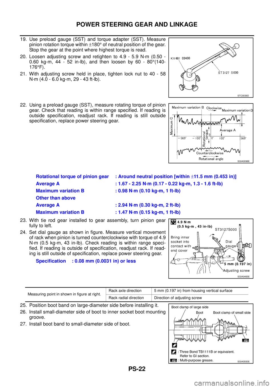
19. Use preload gauge (SST) and torque adapter (SST). Measure
pinion rotation torque within ±180° of neutral position of the gear.
Stop the gear at the point where highest torque is read.
20. Loosen adjusting screw and retighten to 4.9 - 5.9 N·m (0.50 -
0.60 kg-m, 44 - 52 in-lb), and then loosen by 60 - 80°(140-
176°F).
21. With adjusting screw held in place, tighten lock nut to 40 - 58
N·m (4.0 - 6.0 kg-m, 29 - 43 ft-lb).
22. Using a preload gauge (SST), measure rotating torque of pinion
gear. Check that reading is within range specified. If reading is
outside specification, readjust rack. If reading is still outside
specification, replace power steering gear.
23. With tie rod gear installed to gear assembly, turn pinion gear
fully to left.
24. Set dial gauge as shown in figure. Measure vertical movement
of rack when pinion is turned counterclockwise with torque of 4.9
N·m (0.5 kg-m, 43 in-lb). Check reading is within range speci-
fied. If reading is outside of specification, readjust rack. If read-
ing is still outside of specification, replace power steering gear.
25. Position boot band on large-diameter side before installing it.
26. Install small-diameter side of boot to inner socket boot mounting
groove.
27. Install boot band to small-diameter side of boot.
STC0036D
SGIA0098E
Rotational torque of pinion gear : Around neutral position [within ±11.5 mm (0.453 in)]
Average A : 1.67 - 2.25 N·m (0.17 - 0.22 kg-m, 1.3 - 1.6 ft-lb)
Maximum variation B : 0.98 N·m (0.10 kg-m, 1 ft-lb)
Other than above
Average A : 2.94 N·m (0.30 kg-m, 2 ft-lb)
Maximum variation B : 1.47 N·m (0.15 kg-m, 1 ft-lb)
Specification : 0.08 mm (0.0031 in) or less
SGIA0465E
Measuring point in shown in figure at right.Rack axle direction 5 mm (0.197 in) from housing vertical surface
Rack radial direction Direction of adjusting screw
SGIA0550E
Page 2959 of 4179
POWER STEERING GEAR AND LINKAGE
PS-23
C
D
E
F
H
I
J
K
L
MA
B
PS
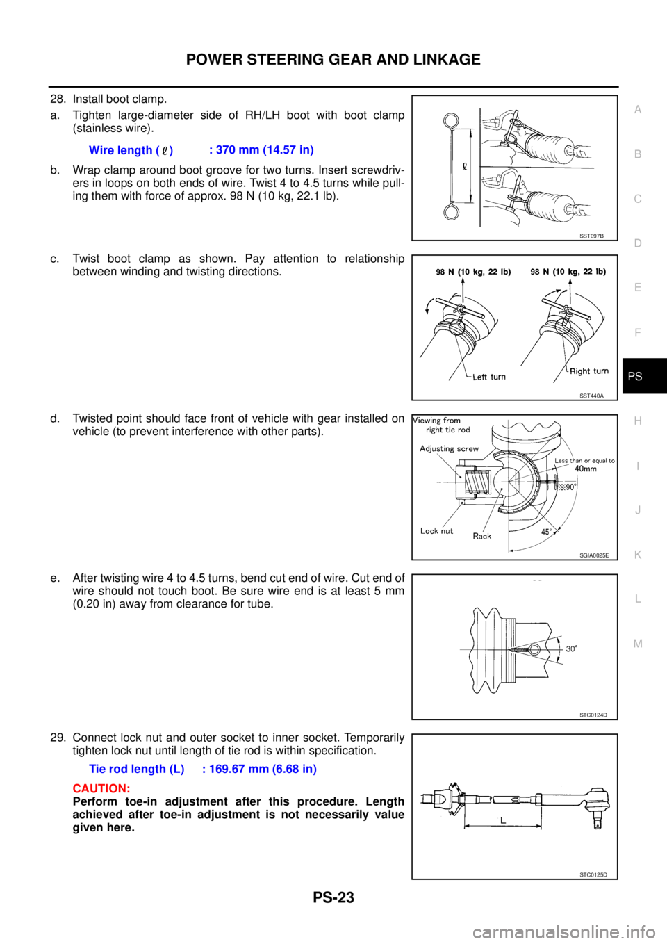
28. Install boot clamp.
a. Tighten large-diameter side of RH/LH boot with boot clamp
(stainless wire).
b. Wrap clamp around boot groove for two turns. Insert screwdriv-
ers in loops on both ends of wire. Twist 4 to 4.5 turns while pull-
ing them with force of approx. 98 N (10 kg, 22.1 lb).
c. Twist boot clamp as shown. Pay attention to relationship
between winding and twisting directions.
d. Twisted point should face front of vehicle with gear installed on
vehicle (to prevent interference with other parts).
e. After twisting wire 4 to 4.5 turns, bend cut end of wire. Cut end of
wire should not touch boot. Be sure wire end is at least 5 mm
(0.20 in) away from clearance for tube.
29. Connect lock nut and outer socket to inner socket. Temporarily
tighten lock nut until length of tie rod is within specification.
CAUTION:
Perform toe-in adjustment after this procedure. Length
achieved after toe-in adjustment is not necessarily value
given here.Wire length ( ): 370 mm (14.57 in)
SST097B
SST440A
SGIA0025E
STC0124D
Tie rod length (L) : 169.67 mm (6.68 in)
STC0125D
Page 2979 of 4179
SERVICE DATA AND SPECIFICATIONS (SDS)
PS-43
C
D
E
F
H
I
J
K
L
MA
B
PS
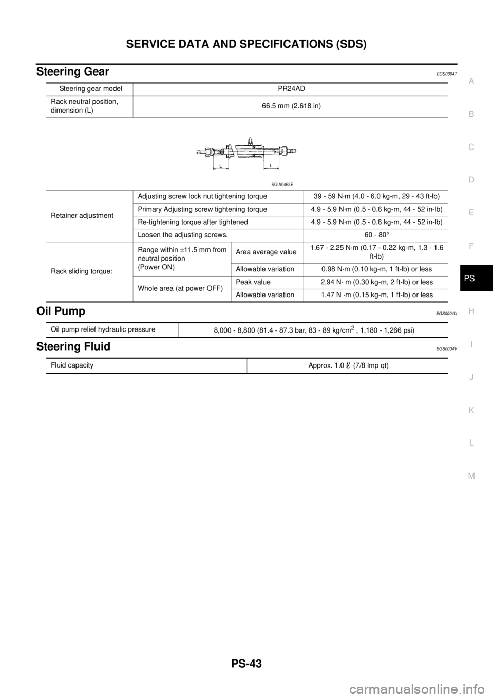
Steering GearEGS0004T
Oil PumpEGS0004U
Steering FluidEGS0004V
Steering gear model PR24AD
Rack neutral position,
dimension (L)66.5 mm (2.618 in)
Retainer adjustmentAdjusting screw lock nut tightening torque 39 - 59 N·m (4.0 - 6.0 kg-m, 29 - 43 ft-lb)
Primary Adjusting screw tightening torque 4.9 - 5.9 N·m (0.5 - 0.6 kg-m, 44 - 52 in-lb)
Re-tightening torque after tightened 4.9 - 5.9 N·m (0.5 - 0.6 kg-m, 44 - 52 in-lb)
Loosen the adjusting screws. 60 - 80°
Rack sliding torque:Range within ±11.5 mm from
neutral position
(Power ON)Area average value1.67 - 2.25 N·m (0.17 - 0.22 kg-m, 1.3 - 1.6
ft-lb)
Allowable variation 0.98 N·m (0.10 kg-m, 1 ft-lb) or less
Whole area (at power OFF)Peak value 2.94 N· m (0.30 kg-m, 2 ft-lb) or less
Allowable variation 1.47 N ·m (0.15 kg-m, 1 ft-lb) or less
SGIA0463E
Oil pump relief hydraulic pressure
8,000 - 8,800 (81.4 - 87.3 bar, 83 - 89 kg/cm2 , 1,180 - 1,266 psi)
Fluid capacity
Approx. 1.0 (7/8 lmp qt)
Page 2986 of 4179
SB-6
SEAT BELT WARNING SYSTEM
SEAT BELT WARNING SYSTEMPFP:25045
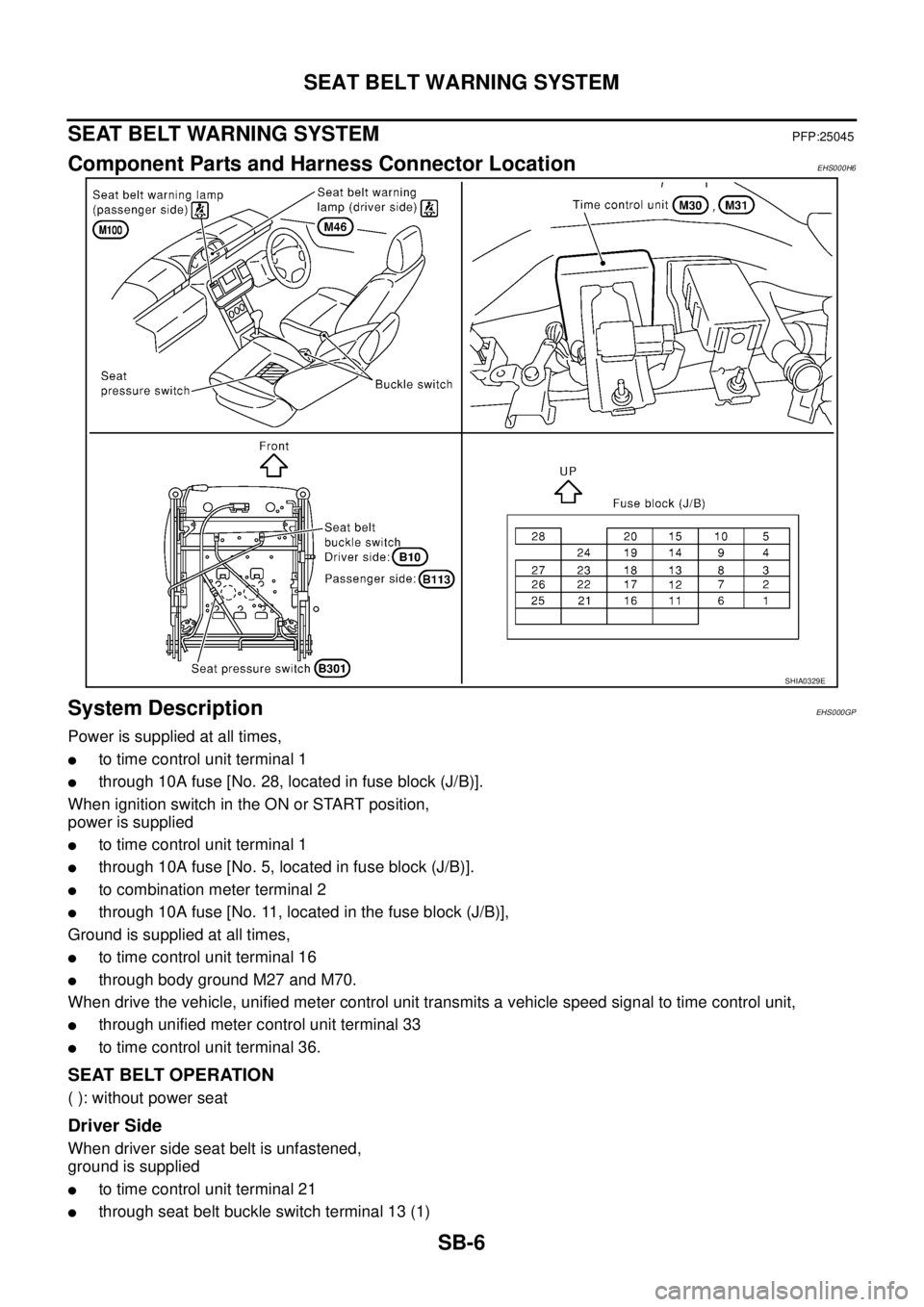
Component Parts and Harness Connector LocationEHS000H6
System DescriptionEHS000GP
Power is supplied at all times,
�to time control unit terminal 1
�through 10A fuse [No. 28, located in fuse block (J/B)].
When ignition switch in the ON or START position,
power is supplied
�to time control unit terminal 1
�through 10A fuse [No. 5, located in fuse block (J/B)].
�to combination meter terminal 2
�through 10A fuse [No. 11, located in the fuse block (J/B)],
Ground is supplied at all times,
�to time control unit terminal 16
�through body ground M27 and M70.
When drive the vehicle, unified meter control unit transmits a vehicle speed signal to time control unit,
�through unified meter control unit terminal 33
�to time control unit terminal 36.
SEAT BELT OPERATION
( ): without power seat
Driver Side
When driver side seat belt is unfastened,
ground is supplied
�to time control unit terminal 21
�through seat belt buckle switch terminal 13 (1)
SHIA0329E
Page 2996 of 4179
SB-16
SEAT BELT WARNING SYSTEM
Work FlowEHS001FQ
1. Check the symptom and customer's requests.
2. Understand the outline of system. Refer to SB-6, "
System Description" .
3. According to the trouble diagnosis chart, repair or replace the cause of the malfunction. Refer to SB-16,
"Trouble Diagnosis Chart by Symptom" .
4. Does power seat system operate normally? If Yes, GO TO 5, If No, GO TO 3.
5. INSPECTION END.
Trouble Diagnosis Chart by SymptomEHS000GS
NOTE:
Always check the “Work Flow” before troubleshooting. Refer to SB-16, "
Work Flow" .
Time Control Unit Power Supply and Ground Circuit CheckEHS001FV
1. CHECK FUSE
Check the following.
�Check 10A fuse [No. 5, located in the fuse block (J/B)].
�Check 10A fuse [No. 28, located in the fuse block (J/B)].
OK or NG
OK >> GO TO 2.
NG >> Replace fuse.
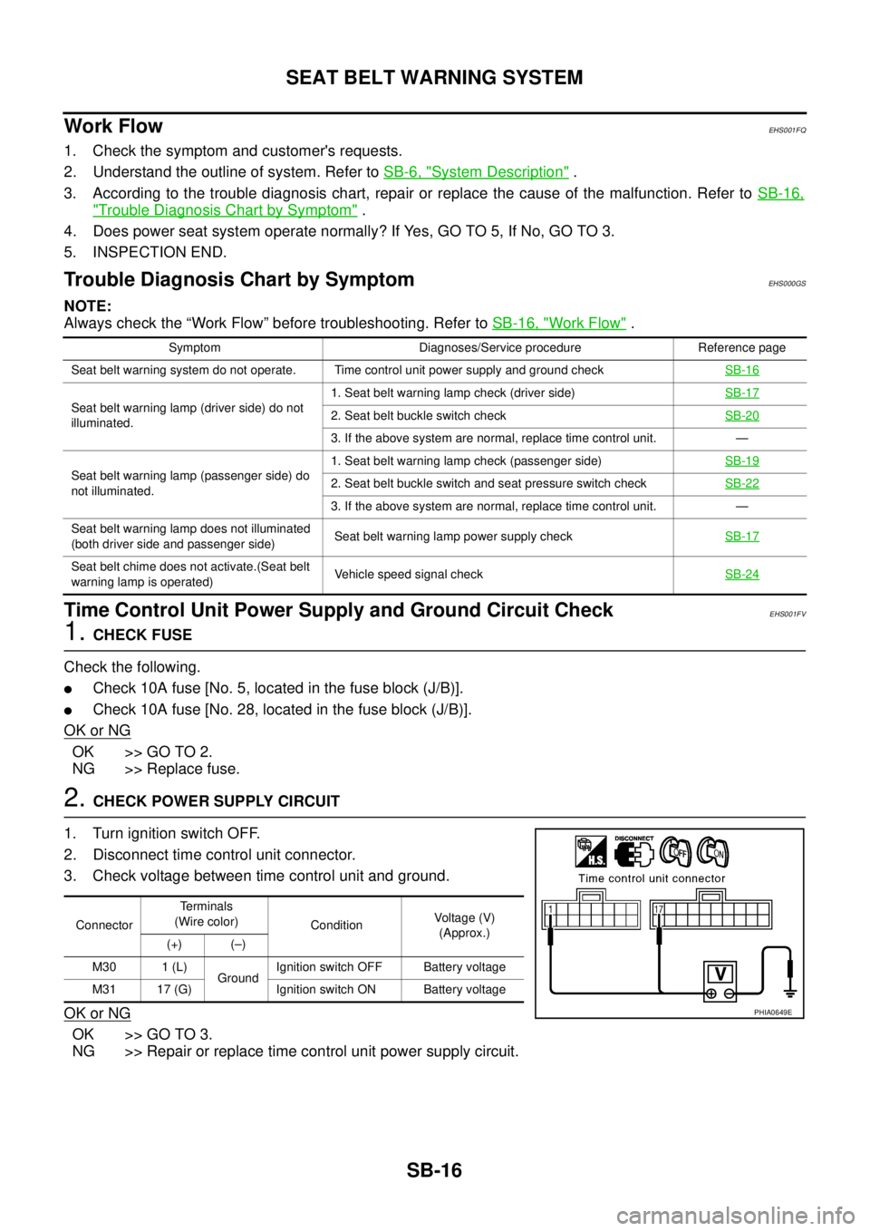
2. CHECK POWER SUPPLY CIRCUIT
1. Turn ignition switch OFF.
2. Disconnect time control unit connector.
3. Check voltage between time control unit and ground.
OK or NG
OK >> GO TO 3.
NG >> Repair or replace time control unit power supply circuit.
Symptom Diagnoses/Service procedure Reference page
Seat belt warning system do not operate. Time control unit power supply and ground checkSB-16
Seat belt warning lamp (driver side) do not
illuminated.1. Seat belt warning lamp check (driver side)SB-172. Seat belt buckle switch checkSB-20
3. If the above system are normal, replace time control unit. —
Seat belt warning lamp (passenger side) do
not illuminated.1. Seat belt warning lamp check (passenger side)SB-19
2. Seat belt buckle switch and seat pressure switch checkSB-22
3. If the above system are normal, replace time control unit. —
Seat belt warning lamp does not illuminated
(both driver side and passenger side) Seat belt warning lamp power supply checkSB-17
Seat belt chime does not activate.(Seat belt
warning lamp is operated) Vehicle speed signal checkSB-24
ConnectorTerminals
(Wire color)
ConditionVoltage (V)
(Approx.)
(+) (–)
M30 1 (L)
GroundIgnition switch OFF Battery voltage
M31 17 (G) Ignition switch ON Battery voltage
PHIA0649E
Page 2997 of 4179
SEAT BELT WARNING SYSTEM
SB-17
C
D
E
F
G
I
J
K
L
MA
B
SB
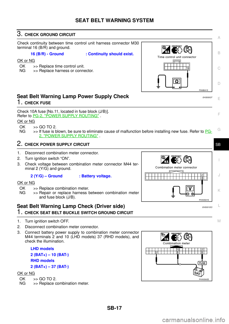
3. CHECK GROUND CIRCUIT
Check continuity between time control unit harness connector M30
terminal 16 (B/R) and ground.
OK or NG
OK >> Replace time control unit.
NG >> Replace harness or connector.
Seat Belt Warning Lamp Power Supply CheckEHS000GT
1. CHECK FUSE
Check 10A fuse [No.11, located in fuse block (J/B)].
Refer to PG-2, "
POWER SUPPLY ROUTING" .
OK or NG
OK >> GO TO 2.
NG >> If fuse is blown, be sure to eliminate cause of malfunction before installing new fuse. Refer to PG-
2, "POWER SUPPLY ROUTING" .
2. CHECK POWER SUPPLY CIRCUIT
1. Disconnect combination meter connector.
2. Turn ignition switch “ON”.
3. Check voltage between combination meter connector M44 ter-
minal 2 (Y/G) and ground.
OK or NG
OK >> Replace combination meter.
NG >> Repair or replace harness between combination meter
and fuse block (J/B).
Seat Belt Warning Lamp Check (Driver side)EHS001DO
1. CHECK SEAT BELT BUCKLE SWITCH GROUND CIRCUIT
1. Turn ignition switch OFF.
2. Disconnect combination meter connector.
3. Connect battery power supply to combination meter connector
M44 terminals 2 and 10 (LHD models) 37 (RHD models), and
check the illumination.
OK or NG
OK >> GO TO 2.
NG >> Replace combination meter.16 (B/R) - Ground : Continuity should exist.
PIIA8641E
2 (Y/G) – Ground : Battery voltage.
PHIA0641E
LHD models
2 (BAT+) – 10 (BAT-)
RHD models
2 (BAT+) – 37 (BAT-)
PHIA0642E
Page 3032 of 4179
SRS-28
TROUBLE DIAGNOSIS
Trouble Diagnosis: “AIR BAG” Warning Lamp Does Not Turn OffEHS000OB
DIAGNOSTIC PROCEDURE 5
1. CHECK THE DEPLOYMENT OF AIR BAG MODULE
Is air bag module deployed?
YES or NO
YES >> Refer to SRS-48, "COLLISION DIAGNOSIS" .
NO >> GO TO 2.
2. CHECK THE AIR BAG FUSE
Check 10A fuse [No. 9, located in fuse block (J/B)].
Refer to PG-2, "
POWER SUPPLY ROUTING" .
OK or NG
OK >> GO TO 4.
NG >> GO TO 3.
3. CHECK AIR BAG FUSE AGAIN
Replace “AIR BAG” fuse and turn ignition switch ON.
Is
“AIR BAG” fuse blown again?
YES >> Repair main harness.
NO >>INSPECTION END
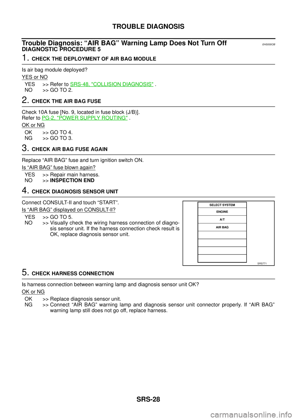
4. CHECK DIAGNOSIS SENSOR UNIT
Connect CONSULT-II and touch “START”.
Is
“AIR BAG” displayed on CONSULT-ll?
YES >> GO TO 5.
NO >> Visually check the wiring harness connection of diagno-
sis sensor unit. If the harness connection check result is
OK, replace diagnosis sensor unit.
5. CHECK HARNESS CONNECTION
Is harness connection between warning lamp and diagnosis sensor unit OK?
OK or NG
OK >> Replace diagnosis sensor unit.
NG >> Connect “AIR BAG” warning lamp and diagnosis sensor unit connector properly. If “AIR BAG”
warning lamp still does not go off, replace harness.
SRS771
Page 3033 of 4179
TROUBLE DIAGNOSIS
SRS-29
C
D
E
F
G
I
J
K
L
MA
B
SRS
Trouble Diagnosis: “AIR BAG” Warning Lamp Does Not Turn OnEHS000OC
DIAGNOSTIC PROCEDURE 6
1. CHECK “METER” FUSE
Check 10A fuse [No. 11, located in fuse block (J/B)].
Refer to PG-2, "
POWER SUPPLY ROUTING" .
OK or NG
OK >> GO TO 3.
NG >> GO TO 2.
2. CHECK “METER” FUSE AGAIN
Replace meter fuse and turn ignition switch ON.
Is meter fuse blown again?
YES >> Repair the related harness.
NO >>INSPECTION END
3. CHECK HARNESS CONNECTION BETWEEN DIAGNOSIS SENSOR UNIT AND COMBINATION
METER
Disconnect diagnosis sensor unit connector and turn ignition switch ON.
Does
“AIR BAG” warning lamp turn on?
YES >> Replace diagnosis sensor unit.
NO >> Replace combination meter assembly.