HARNESS CONNECTOR
PG-71
C
D
E
F
G
H
I
J
L
MA
B
PG
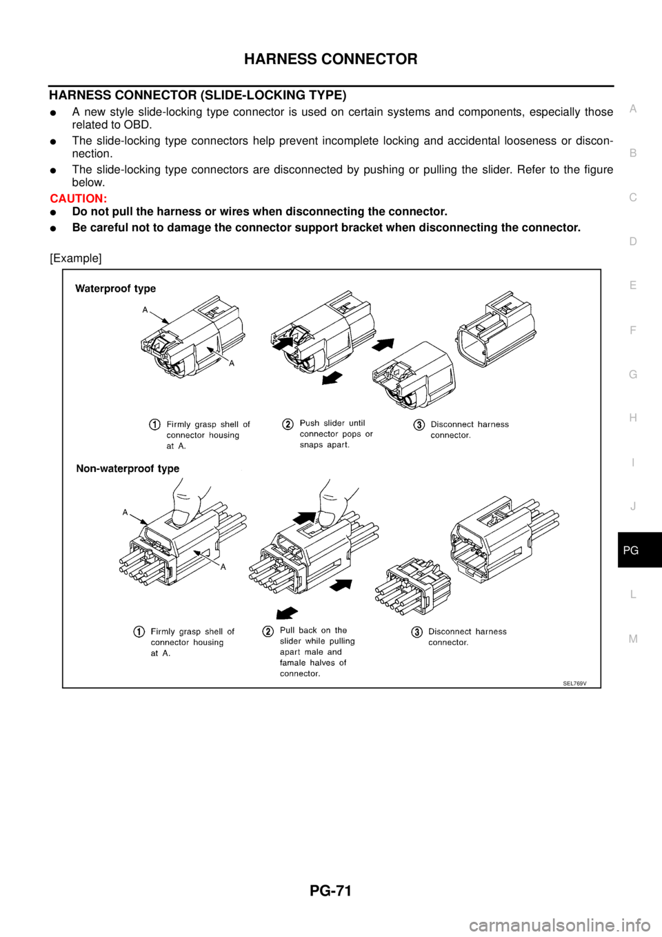
HARNESS CONNECTOR (SLIDE-LOCKING TYPE)
�A new style slide-locking type connector is used on certain systems and components, especially those
related to OBD.
�The slide-locking type connectors help prevent incomplete locking and accidental looseness or discon-
nection.
�The slide-locking type connectors are disconnected by pushing or pulling the slider. Refer to the figure
below.
CAUTION:
�Do not pull the harness or wires when disconnecting the connector.
�Be careful not to damage the connector support bracket when disconnecting the connector.
[Example]
SEL769V
LT-14
HEADLAMP
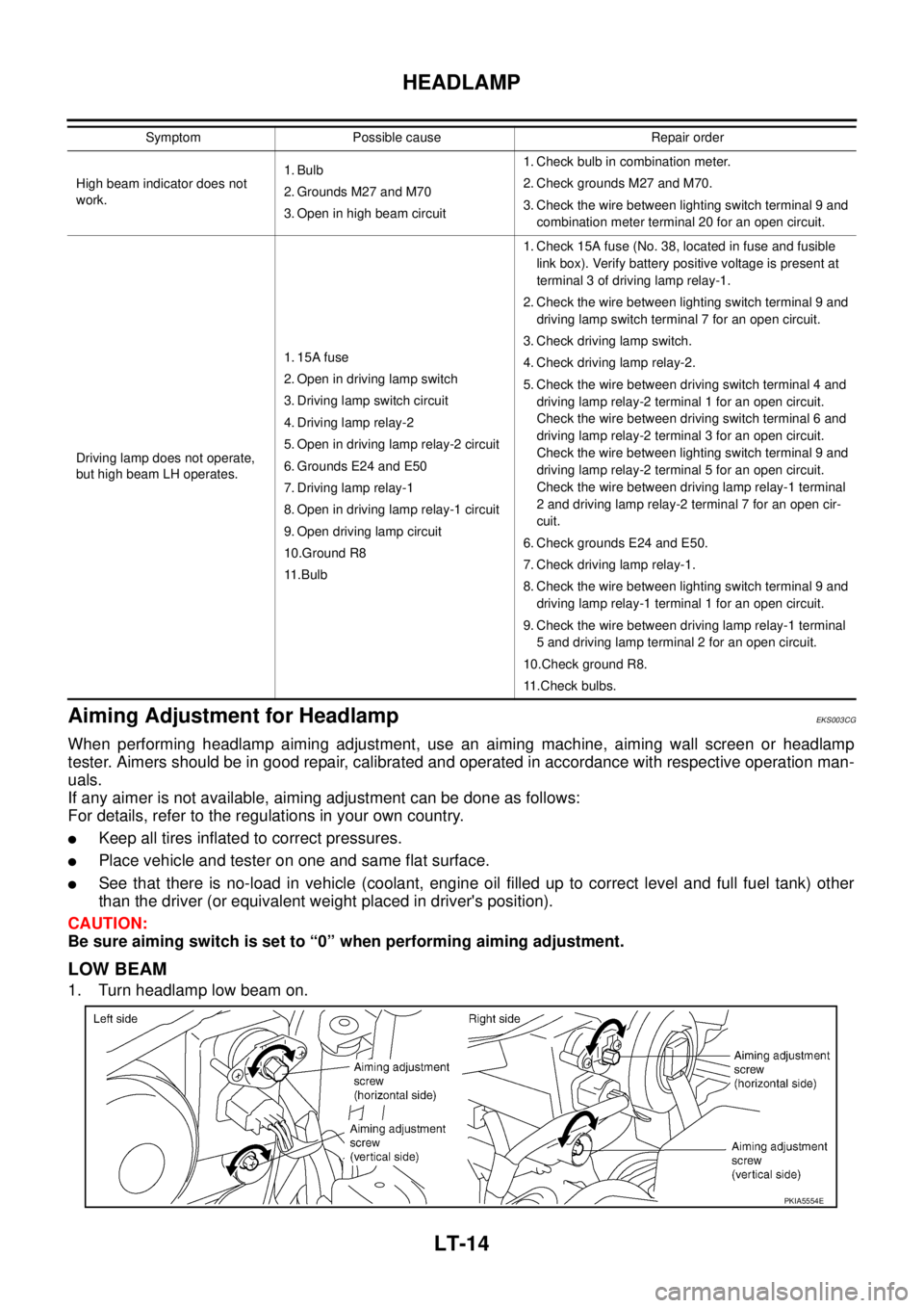
Aiming Adjustment for HeadlampEKS003CG
When performing headlamp aiming adjustment, use an aiming machine, aiming wall screen or headlamp
tester. Aimers should be in good repair, calibrated and operated in accordance with respective operation man-
uals.
If any aimer is not available, aiming adjustment can be done as follows:
For details, refer to the regulations in your own country.
�Keep all tires inflated to correct pressures.
�Place vehicle and tester on one and same flat surface.
�See that there is no-load in vehicle (coolant, engine oil filled up to correct level and full fuel tank) other
than the driver (or equivalent weight placed in driver's position).
CAUTION:
Be sure aiming switch is set to “0” when performing aiming adjustment.
LOW BEAM
1. Turn headlamp low beam on.
High beam indicator does not
work.1. Bulb
2. Grounds M27 and M70
3. Open in high beam circuit1. Check bulb in combination meter.
2. Check grounds M27 and M70.
3. Check the wire between lighting switch terminal 9 and
combination meter terminal 20 for an open circuit.
Driving lamp does not operate,
but high beam LH operates.1. 15A fuse
2. Open in driving lamp switch
3. Driving lamp switch circuit
4. Driving lamp relay-2
5. Open in driving lamp relay-2 circuit
6. Grounds E24 and E50
7. Driving lamp relay-1
8. Open in driving lamp relay-1 circuit
9. Open driving lamp circuit
10.Ground R8
11 . B u l b1. Check 15A fuse (No. 38, located in fuse and fusible
link box). Verify battery positive voltage is present at
terminal 3 of driving lamp relay-1.
2. Check the wire between lighting switch terminal 9 and
driving lamp switch terminal 7 for an open circuit.
3. Check driving lamp switch.
4. Check driving lamp relay-2.
5. Check the wire between driving switch terminal 4 and
driving lamp relay-2 terminal 1 for an open circuit.
Check the wire between driving switch terminal 6 and
driving lamp relay-2 terminal 3 for an open circuit.
Check the wire between lighting switch terminal 9 and
driving lamp relay-2 terminal 5 for an open circuit.
Check the wire between driving lamp relay-1 terminal
2 and driving lamp relay-2 terminal 7 for an open cir-
cuit.
6. Check grounds E24 and E50.
7. Check driving lamp relay-1.
8. Check the wire between lighting switch terminal 9 and
driving lamp relay-1 terminal 1 for an open circuit.
9. Check the wire between driving lamp relay-1 terminal
5 and driving lamp terminal 2 for an open circuit.
10.Check ground R8.
11.Check bulbs. Symptom Possible cause Repair order
PKIA5554E
LT-66
ILLUMINATION
ILLUMINATIONPFP:27545
System Description EKS003C7
Power is supplied at all times
�through 10A fuse [No. 31, located in the fuse and fusible link box]
�to lighting switch terminal 11.
The lighting switch must be in the 1ST or 2ND position for illumination.
The following chart shows the power and ground connector terminals for the components included in the illu-
mination system.
Component Connector No. Power terminal Ground terminal
Headlamp washier switch M23 3 4
Headlamp aiming switch M24 3 4
Door mirror remote control switch M26 10 1
ESP off switch M25 3 4
Hazard switch M51 7 8
4WD mode switch M39 4 3
Rear window defogger switch M50 5 6
A/C auto amp. M52 12 11
Combination meter (LHD models) M46 56 66
Combination meter (RHD models) M46 45 56
Audio M42 2 1
CD auto changer M82 34 35
Heater control panel M55 2 6
A/T device M58 3 4
Cigarette lighter M56 3 2
Heated seat switch LH (LHD models) B131 5 6
Heated seat switch RH (LHD models) B132 5 6
Heated seat switch LH (RHD models) B35 5 6
Heated seat switch RH (RHD models) B34 5 6