Page 289 of 4179
SERVICE DATA AND SPECIFICATIONS (SDS)
EM-237
[YD22DDTi]
C
D
E
F
G
H
I
J
K
L
MA
EM
CYLINDER HEAD
Unit: mm (in)
VA LV E
Valve Dimensions
Unit: mm (in)
Valve Clearance
Unit: mm (in)
*: Approximately 80°C (176°F) Item Standard Limit
Cylinder head distortion Less than 0.03 (0.0012) 0.1 (0.004)
JEM204G
Valve head diameter “D”Intake 28.0 - 28.3 (1.102 - 1.114)
Exhaust 26.0 - 26.3 (1.024 - 1.035)
Valve length “L”Intake 106.72 (4.2016)
Exhaust 106.36 (4.1874)
Valve stem diameter “d”Intake 5.965 - 5.980 (0.2348 - 0.2354)
Exhaust 5.945 - 5.960 (0.2341 - 0.2346)
Valve seat angle “α”Intake
45 degrees 15′ - 45 degrees 45′
Exhaust
Valve margin “T”Intake 1.38 (0.0543)
Exhaust 1.48 (0.0583)
Valve margin “T” limitMore than 1.0 (0.039)
Valve stem end surface grinding limit Less than 0.2 (0.008)
SEM188
Item Cold Hot* (Reference data)
Intake 0.24 - 0.32 (0.0094 - 0.0126) 0.274 - 0.386 (0.0108 - 0.0152)
Exhaust 0.26 - 0.34 (0.0102 - 0.0134) 0.308 - 0.432 (0.0121 - 0.0170)
Page 2446 of 4179
AT-410
[ALL]
ON-VEHICLE SERVICE
Differential Side Oil Seal ReplacementECS0040F
COMPONENTS
1. Remove exhaust front tube. Refer to EX-2, "Removal and Installation"
2. Remove left side drive shaft assemblies. Refer to FAX-11, "FRONT DRIVE SHAFT" .
3. Remove transfer from right side of transaxle.
Refer to TF-55, "
Removal and Installation" .
4. Remove differential side oil seal using a flat-bladed screwdriver.
CAUTION:
Be careful not to scratch transaxle case.
Installation
1. As shown below, use a drift to drive the differential side oil seals
into the case until it is flush. Refer to dimensions A.
Unit: mm (in)
NOTE:
The differential side oil seal pulling direction is used as the refer-
ence.
1. transaxle assembly 2. LH differential side oil seal 3. RH differential side oil seal
SCIA4970E
SCIA2792E
AB
-0.5 to 0.5 (-0.020 to 0.020)−0.5 to 0.5 (−0.020 to 0.020)
SCIA0791E
Page 2545 of 4179
![NISSAN X-TRAIL 2003 Service Repair Manual ASSEMBLY
AT-509
[ALL]
D
E
F
G
H
I
J
K
L
MA
B
AT
9. Remove converter housing from transaxle case.
10. Remove final drive assembly from transaxle case.
11. Remove differential side bearing outer race](/manual-img/5/57404/w960_57404-2544.png "NISSAN X-TRAIL 2003 Service Repair Manual ASSEMBLY
AT-509
[ALL]
D
E
F
G
H
I
J
K
L
MA
B
AT
9. Remove converter housing from transaxle case.
10. Remove final drive assembly from transaxle case.
11. Remove differential side bearing outer race")
ASSEMBLY
AT-509
[ALL]
D
E
F
G
H
I
J
K
L
MA
B
AT
9. Remove converter housing from transaxle case.
10. Remove final drive assembly from transaxle case.
11. Remove differential side bearing outer race from transaxle case.
12. Reinstall differential side bearing outer race and differential side
bearing adjusting shim selected from SDS table on transaxle
case. Refer to AT- 5 3 6 , "
DIFFERENTIAL SIDE BEARING PRE-
LOAD ADJUSTING SHIMS" .
13. Reinstall converter housing on transaxle case and tighten con-
verter housing mounting bolts to the specified torque. Refer to
AT- 4 1 6 , "
Components" .
14. Insert SST and measure turning torque of final drive assembly.
�Turn final drive assembly in both directions several times
to seat bearing rollers correctly.
�When old bearing is used again, turning torque will be
slightly less than the above.
�Make sure torque is close to the specified range.
REDUCTION PINION GEAR BEARING PRELOAD
1. Remove converter housing and final drive assembly from tran-
saxle case.
2. Select proper thickness of reduction pinion gear adjusting shim
using the following procedures.
a. Place reduction pinion gear on transaxle case as shown.
b. Place idler gear bearing on transaxle case.
c. Measure the dimensions “B” “C” and “D” and calculate dimen-
sion “A”.
SAT010FC
Turning torque of final drive assembly (New bearing):
0.78 - 1.37 N-m (0.8 - 14.0 kg-cm, 6.9 - 12.2 in-lb)
Preload adapter: KV38105210
SAT188FA
SAT332DA
A = D − (B + C)
“A”: Distance between the surface of idler gear bear-
ing inner race and the adjusting shim mating
surface of reduction pinion gear.
SAT333DA
Page 2548 of 4179
AT-512
[ALL]
ASSEMBLY
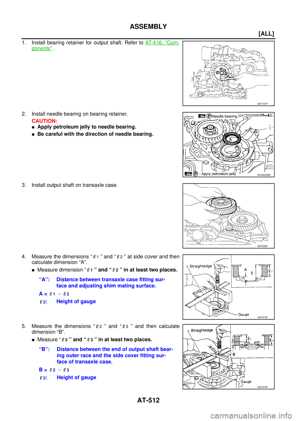
1. Install bearing retainer for output shaft. Refer to AT- 4 1 6 , "Com-
ponents" .
2. Install needle bearing on bearing retainer.
CAUTION:
�Apply petroleum jelly to needle bearing.
�Be careful with the direction of needle bearing.
3. Install output shaft on transaxle case.
4. Measure the dimensions “
1 ” and “2 ” at side cover and then
calculate dimension “A”.
�Measure dimension “1 ” and “2 ” in at least two places.
5. Measure the dimensions “
2 ” and “3 ” and then calculate
dimension “B”.
�Measure “2 ” and “3 ” in at least two places.
SAT191F
SCIA4329E
SAT035F
“A”: Distance between transaxle case fitting sur-
face and adjusting shim mating surface.
A =
1 − 2
2
:Height of gauge
SAT374F
“B”: Distance between the end of output shaft bear-
ing outer race and the side cover fitting sur-
face of transaxle case.
B =
2 − 3
2
:Height of gauge
SAT375F
Page 2556 of 4179
AT-520
[ALL]
ASSEMBLY
18. Install reverse clutch assembly on input shaft assembly (high
clutch drum).
Adjustment (2)ECS004MG
When any parts listed below are replaced, adjust total end play and reverse clutch end play.
TOTAL END PLAY
�Measure the clearance between reverse clutch drum and needle
bearing for oil pump cover.
�Select proper thickness of bearing race so that end play is within
specifications.
1. Measure dimensions “K” and “L” and then calculate dimension
“J”.
SCIA4461E
Part name Total end play Reverse clutch end play
transaxle case��
Overrun clutch hub��
Rear internal gear��
Rear planetary carrier��
Rear sun gear��
Front planetary carrier��
Front sun gear��
High clutch hub��
High clutch drum��
Oil pump cover��
Reverse clutch drum —�
SCIA3661E
SCIA3662E
Page 2558 of 4179
AT-522
[ALL]
ASSEMBLY
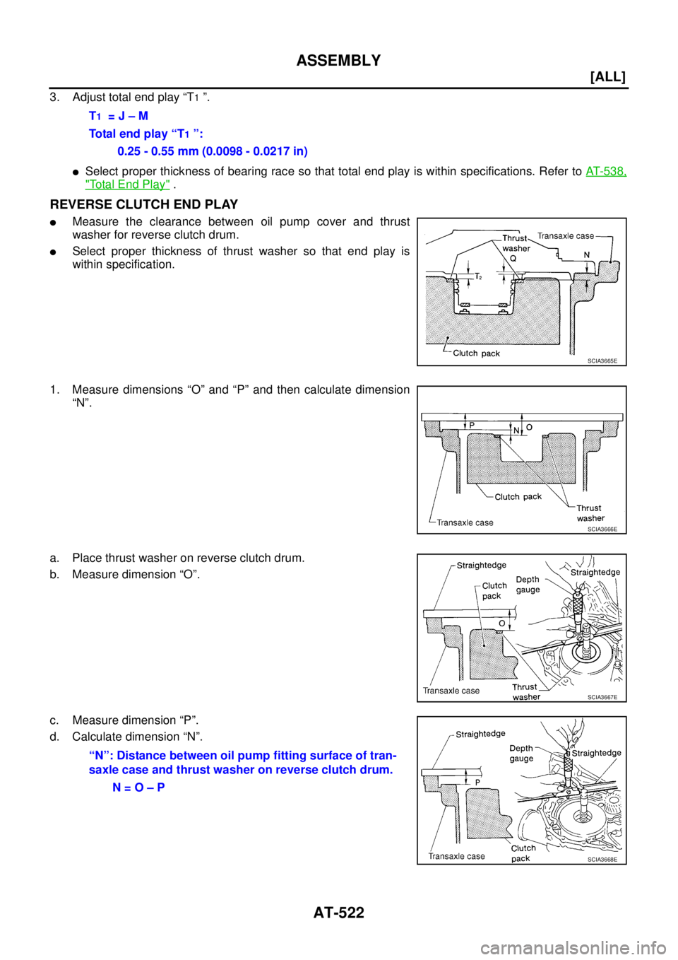
3. Adjust total end play “T1 ”.
�Select proper thickness of bearing race so that total end play is within specifications. Refer to AT- 5 3 8 ,
"Total End Play" .
REVERSE CLUTCH END PLAY
�Measure the clearance between oil pump cover and thrust
washer for reverse clutch drum.
�Select proper thickness of thrust washer so that end play is
within specification.
1. Measure dimensions “O” and “P” and then calculate dimension
“N”.
a. Place thrust washer on reverse clutch drum.
b. Measure dimension “O”.
c. Measure dimension “P”.
d. Calculate dimension “N”.T
1 = J – M
Total end play “T
1 ”:
0.25 - 0.55 mm (0.0098 - 0.0217 in)
SCIA3665E
SCIA3666E
SCIA3667E
“N”: Distance between oil pump fitting surface of tran-
saxle case and thrust washer on reverse clutch drum.
N = O – P
SCIA3668E
Page 2559 of 4179
ASSEMBLY
AT-523
[ALL]
D
E
F
G
H
I
J
K
L
MA
B
AT
2. Measure dimensions “R” and “S” and then calculate dimension
“Q”.
a. Measure dimension “R”.
b. Measure dimension “S”.
c. Calculate dimension “Q”.
3. Adjust reverse clutch end play “T
2 ”.
�Select proper thickness of thrust washer so that reverse clutch end play is within specifications. Refer
to AT- 5 3 9 , "
Reverse Clutch End Play" .
Assembly (3)ECS004MH
1. Install anchor end pin and lock nut on transaxle case.
CAUTION:
Do not reuse anchor end pin.
2. Place brake band and strut on outside of reverse clutch drum.
Tighten anchor end pin just enough so that brake band is evenly
fitted on reverse clutch drum.
SAT384D
SAT385D
“Q”: Distance between transaxle case fitting surface
and thrust washer mating surface.
Q = R – S
SAT386D
T2 = N – Q
Reverse clutch end play:
0.61 - 1.0 mm (0.0240 - 0.039 in)
SAT196F
Page 2643 of 4179

1. Measure the points F, H, I, R and U shown in t")
TRANSFER ASSEMBLY
TF-67
C
E
F
G
H
I
J
K
L
MA
B
TF
SELECTING ADJUSTING SHIMS
Measurement points
Gear Ring Bearing Adjusting Shim (Transfer Case Side)
1. Measure the points F, H, I, R and U shown in the measurement points.
2. Convert the values F, H, I, R and U according to the standards below.
3. Check dimension Z on the drive gear side face.
NOTE:
Dimension Z indicates the difference between the optimum engagement and the standard dimensions in
increments of 0.01mm (0.0004 in) written on the drive gear side face.
4. Use the formula below to calculate gear ring bearing adjusting shim (transfer case side) thickness T
1 .
5. Select the gear ring bearing adjusting shim (transfer case side).
�For information on selecting an adjusting shim, refer to TF-74, "Gear ring Bearing Adjusting Shim
(Transfer Case Side)" .
CAUTION:
�Only one adjusting shim can be selected.
�If no adjusting shim with the calculated value is available, select the thicker and closest one.
Gear Ring Bearing Adjusting Shim (Adapter Case Side)
1. Measure the points F, H, J, K, U and V shown in the measurement points.
2. Convert the values F, H, J, K, U and V according to the standards below.
SDIA1179E
F: Value obtained by subtracting 163.00 mm (6.42 in) from
the reading [in increments of 0.01 mm (0.0004 in)].
H: Value obtained by subtracting 83.00 mm (3.27 in) from
the reading [in increments of 0.01 mm (0.0004 in)].
I: Value obtained by subtracting 131.90 mm (5.19 in) from
the reading [in increments of 0.01 mm (0.0004 in)].
R: Value obtained by subtracting 17.00 mm (0.67 in) from
the reading [in increments of 0.01 mm (0.0004 in)].
U: Value obtained by subtracting 89.50 mm (3.524 in) from
the reading [in increments of 0.01 mm (0.0004 in)].
T
1 = (I - F + H + Z - U - R) × 0.01 mm (0.0004 in) + 1.49 mm (0.0587 in)
![NISSAN X-TRAIL 2003 Service Repair Manual SERVICE DATA AND SPECIFICATIONS (SDS)
EM-237
[YD22DDTi]
C
D
E
F
G
H
I
J
K
L
MA
EM
CYLINDER HEAD
Unit: mm (in)
VA LV E
Valve Dimensions
Unit: mm (in)
Valve Clearance
Unit: mm (in)
*: Approximately 80](/manual-img/5/57404/w960_57404-288.png "NISSAN X-TRAIL 2003 Service Repair Manual SERVICE DATA AND SPECIFICATIONS (SDS)
EM-237
[YD22DDTi]
C
D
E
F
G
H
I
J
K
L
MA
EM
CYLINDER HEAD
Unit: mm (in)
VA LV E
Valve Dimensions
Unit: mm (in)
Valve Clearance
Unit: mm (in)
*: Approximately 80")
![NISSAN X-TRAIL 2003 Service Repair Manual AT-410
[ALL]
ON-VEHICLE SERVICE
Differential Side Oil Seal ReplacementECS0040F
COMPONENTS
1. Remove exhaust front tube. Refer to EX-2, "Removal and Installation"
2. Remove left side drive shaft asse](/manual-img/5/57404/w960_57404-2445.png "NISSAN X-TRAIL 2003 Service Repair Manual AT-410
[ALL]
ON-VEHICLE SERVICE
Differential Side Oil Seal ReplacementECS0040F
COMPONENTS
1. Remove exhaust front tube. Refer to EX-2, \"Removal and Installation\"
2. Remove left side drive shaft asse")
![NISSAN X-TRAIL 2003 Service Repair Manual AT-520
[ALL]
ASSEMBLY
18. Install reverse clutch assembly on input shaft assembly (high
clutch drum).
Adjustment (2)ECS004MG
When any parts listed below are replaced, adjust total end play and rever](/manual-img/5/57404/w960_57404-2555.png "NISSAN X-TRAIL 2003 Service Repair Manual AT-520
[ALL]
ASSEMBLY
18. Install reverse clutch assembly on input shaft assembly (high
clutch drum).
Adjustment (2)ECS004MG
When any parts listed below are replaced, adjust total end play and rever")
![NISSAN X-TRAIL 2003 Service Repair Manual ASSEMBLY
AT-523
[ALL]
D
E
F
G
H
I
J
K
L
MA
B
AT
2. Measure dimensions “R” and “S” and then calculate dimension
“Q”.
a. Measure dimension “R”.
b. Measure dimension “S”.
c. Calcula](/manual-img/5/57404/w960_57404-2558.png "NISSAN X-TRAIL 2003 Service Repair Manual ASSEMBLY
AT-523
[ALL]
D
E
F
G
H
I
J
K
L
MA
B
AT
2. Measure dimensions “R” and “S” and then calculate dimension
“Q”.
a. Measure dimension “R”.
b. Measure dimension “S”.
c. Calcula")