TF-68
TRANSFER ASSEMBLY
3. Check dimension Z on the drive gear side face.
NOTE:
Dimension Z indicates the difference between the optimum engagement and the standard dimensions in
increments of 0.01mm (0.0004 in) written on the drive gear side face.
4. Use the formula below to calculate gear ring bearing adjusting shim (adapter case side) thickness T
2 .
5. Select the gear ring bearing adjusting shim (adapter case side).
�For information on selecting an adjusting shim, refer to TF-75, "Gear ring Bearing Adjusting Shim
(Adapter Case Side)" .
CAUTION:
�Only one adjusting shim can be selected.
�If no adjusting shim with the calculated value is available, select the thicker and closest one.
Pinion Sleeve Shim
1. Measure the points L, N and Q shown in the measurement points.
2. Check the dimension S written on the gear end of the drive pinion.
NOTE:
The dimension S indicates the difference between the optimum engagement and the standard dimensions
in increments of 0.01 mm (0.0004 in) written on the gear end of the drive pinion.
3. Use the formula below to calculate pinion sleeve shim thickness T
3 .
4. Select the pinion sleeve shim.
�For information on selecting a pinion sleeve shim, refer to TF-75, "Pinion Sleeve Shim" .
CAUTION:
Only one pinion sleeve shim can be selected.
ASSEMBLY
Transfer Case
1. Select the gear ring bearing adjusting shim (transfer case side). Refer to TF-67, "SELECTING ADJUST-
ING SHIMS" . F: Value obtained by subtracting 163.00 mm (6.42 in) from
the reading [in increments of 0.01 mm (0.0004 in)].
H: Value obtained by subtracting 83.00 mm (3.27 in) from
the reading [in increments of 0.01 mm (0.0004 in)].
J: Value obtained by subtracting 109.50 mm (4.31 in) from
the reading [in increments of 0.01 mm (0.0004 in)].
K: Value obtained by subtracting 14.40 mm (0.5669 in) from
the reading [in increments of 0.01 mm (0.0004 in)].
U: Value obtained by subtracting 89.50 mm (3.524 in) from
the reading [in increments of 0.01 mm (0.0004 in)].
V: Value obtained by subtracting 17.00 mm (0.67 in) from
the reading [in increments of 0.01 mm (0.0004 in)].
T
2 = (K + F - H - Z + U - J - V) × 0.01 mm (0.0004 in) + 1.49 mm (0.0587 in)
T
3 = [74.6 mm (2.937 in) + S] + N + Q - L
FAX-18
FRONT DRIVE SHAFT
Mounting Dimensions
Drive shaft model Applied model Specification Dimension A Dimension B
ZF100SS86 All Left 205 - 215 mm (8.07 - 8.46 in) 70 mm (2.76 in)
ZF100SS86F+BLHD: QR20DE A/T models
RHD: QR25DE A/T models
QR25DE: M/T modelsRight 207 - 213 mm (8.15 - 8.39 in)70 mm (2.76 in)
QR20DE/YD22DDTi: M/T models 50 mm (1.97 in)
BR-6
BRAKE PEDAL
BRAKE PEDALPFP:46501
On-Vehicle Inspection and AdjustmentEFS000C1
Adjust clearance between dash panel and brake pedal upper surface
to the following dimensions.
1. Loosen stop lamp switch by rotating it counter-clockwise by 45°.
2. Loosen input rod lock nut (A), then rotate input rod, set pedal to
the specified height, and tighten lock nut (A).
CAUTION:
Confirm threaded end of input rod remains inside the cle-
vis.
3. Pull pedal by hand and hold it. Press stop lamp switch until its
threaded end contacts the stopper rubber.
4. While holding it against the stopper rubber, turn the switch clock-
wise by 45° and secure it.
CAUTION:
Be sure stopper rubber to stop lamp switch screw threaded
end gap (C) is within the specifications.
5. Check pedal free play.
CAUTION:
Be sure stop lamps go off when pedal is released.
6. Start engine and check brake pedal depressed height.
SFIA0348E
H1Brake pedal heightM/T model 156 - 166 mm (6.14 - 6.54 in)
A/T model 164 - 174 mm (6.46 - 6.85 in)
H
2
Pedal height when depressed
[With engine running and at a depression force of 490 N (50 kg,110.6
lb)]M/T model 80 mm (3.15 in) or more
A/T model 85 mm (3.35 in) or more
C Clearance between stopper rubber and threaded end of stop lamp switch 0.74 - 1.96 mm (0.0291 - 0.0772 in)
A Pedal play3 - 11 mm (0.12 - 0.43 in)
: 16 - 21 N·m (1.6 - 2.2 kg-m, 12 - 15 ft-lb)
SFIA0160E
NAVIGATION SYSTEM
AV-43
C
D
E
F
G
H
I
J
L
MA
B
AV
�In map-matching, alternative routes to reach the destination will
be shown and prioritized, after the road on which the vehicle is
currently driven has been judged and the current-location mark
has been repositioned.
If there is an error in distance and/or direction, the alternative
routes will be shown in different order of priority, and the wrong
road can be avoided.
If two roads are running in parallel, they are of the same priority.
Therefore, the current-location mark may appear on either of
them alternately, depending on maneuvering of the steering
wheel and configuration of the road.
�Map-matching does not function correctly when the road on
which the vehicle is driving is new and not recorded in the map
DVD-ROM, or when the road pattern stored in the map data and
the actual road pattern are different due to repair.
When driving on a road not present in the map, the map-match-
ing function may find another road and position the current-loca-
tion mark on it. Then, when the correct road is detected, the
current-location mark may leap to it.
�Effective range for comparing the vehicle position and travel
direction calculated by the distance and direction with the road
data read from the map DVD-ROM is limited. Therefore, when
there is an excessive gap between the current vehicle position
and the position on the map, correction by map-matching is not possible.
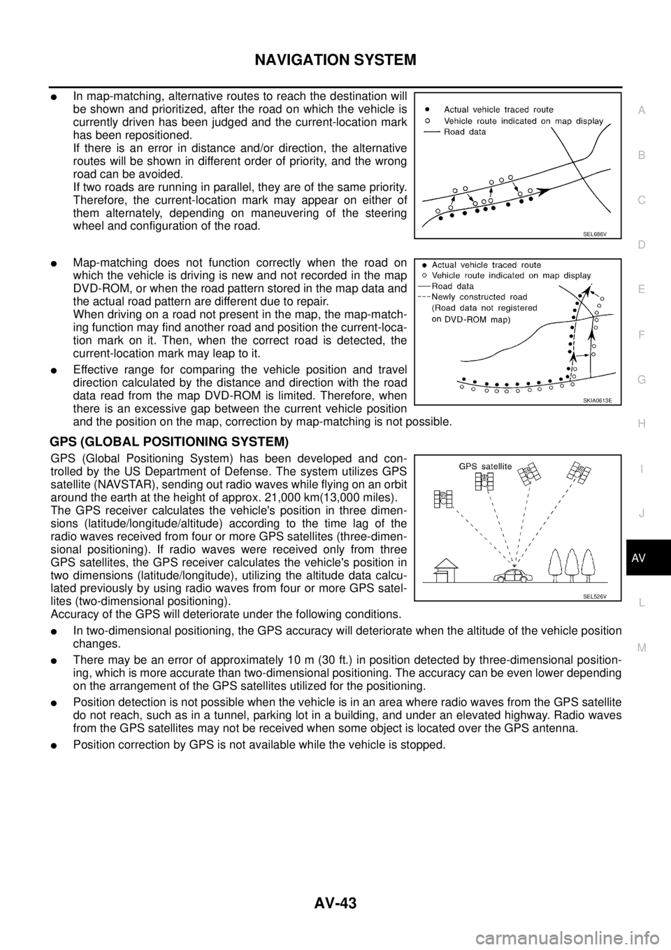
GPS (GLOBAL POSITIONING SYSTEM)
GPS (Global Positioning System) has been developed and con-
trolled by the US Department of Defense. The system utilizes GPS
satellite (NAVSTAR), sending out radio waves while flying on an orbit
around the earth at the height of approx. 21,000 km(13,000 miles).
The GPS receiver calculates the vehicle's position in three dimen-
sions (latitude/longitude/altitude) according to the time lag of the
radio waves received from four or more GPS satellites (three-dimen-
sional positioning). If radio waves were received only from three
GPS satellites, the GPS receiver calculates the vehicle's position in
two dimensions (latitude/longitude), utilizing the altitude data calcu-
lated previously by using radio waves from four or more GPS satel-
lites (two-dimensional positioning).
Accuracy of the GPS will deteriorate under the following conditions.
�In two-dimensional positioning, the GPS accuracy will deteriorate when the altitude of the vehicle position
changes.
�There may be an error of approximately 10 m (30 ft.) in position detected by three-dimensional position-
ing, which is more accurate than two-dimensional positioning. The accuracy can be even lower depending
on the arrangement of the GPS satellites utilized for the positioning.
�Position detection is not possible when the vehicle is in an area where radio waves from the GPS satellite
do not reach, such as in a tunnel, parking lot in a building, and under an elevated highway. Radio waves
from the GPS satellites may not be received when some object is located over the GPS antenna.
�Position correction by GPS is not available while the vehicle is stopped.
SEL686V
SKIA0613E
SEL526V

 70 mm (2.76 in)
ZF100SS86F+BLHD:")