Page 1 of 4179

MODEL T30 SERIES
2004NISSANEUROPES.A.S.
All rights reserved. No part of this Electronic Service Manual may be reproduced or stored in a retrieval system, or transmitted in any
form, or by any means, electronic, mechanical, photocopying, recording or otherwise, without the prior written permission of Nissan
Europe S.A.S., Paris, France.
A GENERAL INFORMATION
B ENGINE
C TRANSMISSION/TRANSAXLE
D DRIVELINE/AXLE
E SUSPENSION F BRAKES
G STEERING H RESTRAINTS
I BODY
J AIR CONDITIONER
K ELECTRICAL
L MAINTENANCE
M INDEXGI General Information
EM Engine Mechanical
LU Engine Lubrication System
CO Engine Cooling System
EC Engine Control System
FL Fuel System
EX Exhaust System
ACC Accelerator Control System
CL Clutch
MT Manual Transaxle
AT Automatic Transaxle
TF Transfer
PR Propeller Shaft
RFD Rear Final Drive
FAX Front Axle
RAX Rear Axle
FSU Front Suspension
RSU Rear Suspension
WT Road Wheels & Tires
BR Brake System
PB Parking Brake System
BRC Brake Control System
PS Power Steering System
SB Seat Belts
SRS Supplemental Restraint System (SRS)
BL Body, Lock & Security System
GW Glasses, Window System & Mirrors
RF Roof
EI Exterior & Interior
IP Instrument Panel
SE Seat
ATC Automatic Air Conditioner
MTC Manual AIr Conditioner
SC Starting & Charging System
LT Lighting System
DI Driver Information System
WW Wiper, Washer & Horn
BCS Body Control System
LAN LAN System
AV Audio Visual, Navigation & Telephone System
PG Power Supply, Ground & Circuit Elements
MA Maintenance
IDX Alphabetical Index
QUICK REFERENCE INDEX
A
B
C
D
E
F
G
H
I
J
K
L
M
Page 15 of 4179
HOW TO USE THIS MANUAL
GI-13
C
D
E
F
G
H
I
J
K
L
MB
GI
Turn ignition switch from “OFF” to
“ON” position.Drive vehicle.
Turn ignition switch from “ON” to
“OFF” position.Disconnect battery negative cable.
Do not start engine, or check with
engine stopped.Depress brake pedal.
Start engine, or check with engine run-
ning.Release brake pedal.
Apply parking brake. Depress accelerator pedal.
Release parking brake. Release accelerator pedal.
Check after engine is warmed up suffi-
ciently.Pin terminal check for SMJ type ECM
and TCM connectors.
For details regarding the terminal
arrangement, refer to the “ELEC-
TRICAL UNITS” electrical reference
page at the end of the manual. Voltage should be measured with a
voltmeter.
Circuit resistance should be measured
with an ohmmeter.
Current should be measured with an
ammeter.
Pulse signal should be checked with
an oscilloscope.
Procedure with CONSULT-II
Procedure without CONSULT-II Symbol Symbol explanation Symbol Symbol explanation
Page 20 of 4179
GI-18
HOW TO USE THIS MANUAL
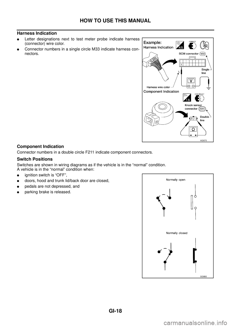
Harness Indication
�Letter designations next to test meter probe indicate harness
(connector) wire color.
�Connector numbers in a single circle M33 indicate harness con-
nectors.
Component Indication
Connector numbers in a double circle F211 indicate component connectors.
Switch Positions
Switches are shown in wiring diagrams as if the vehicle is in the “normal” condition.
A vehicle is in the “normal” condition when:
�ignition switch is “OFF”,
�doors, hood and trunk lid/back door are closed,
�pedals are not depressed, and
�parking brake is released.
AGI070
SGI860
Page 305 of 4179
![NISSAN X-TRAIL 2003 Service Repair Manual ENGINE OIL
LU-7
[QR]
C
D
E
F
G
H
I
J
K
L
MA
LU
ENGINE OILPFP:KLA92
InspectionEBS00KO3
ENGINE OIL LEVEL
NOTE:
Before starting engine, put vehicle horizontally and check the engine oil level. If engin](/manual-img/5/57404/w960_57404-304.png "NISSAN X-TRAIL 2003 Service Repair Manual ENGINE OIL
LU-7
[QR]
C
D
E
F
G
H
I
J
K
L
MA
LU
ENGINE OILPFP:KLA92
InspectionEBS00KO3
ENGINE OIL LEVEL
NOTE:
Before starting engine, put vehicle horizontally and check the engine oil level. If engin")
ENGINE OIL
LU-7
[QR]
C
D
E
F
G
H
I
J
K
L
MA
LU
ENGINE OILPFP:KLA92
InspectionEBS00KO3
ENGINE OIL LEVEL
NOTE:
Before starting engine, put vehicle horizontally and check the engine oil level. If engine is already started, stop
it and allow 10 minutes before checking.
1. Pull out oil level gauge and wipe it clean.
2. Insert oil level gauge and make sure the engine oil level is within
the range shown in the figure.
3. If it is out of range, adjust it.
ENGINE OIL APPEARANCE
�Check engine oil for white turbidity or heavy contamination.
�If engine oil becomes turbid and white, it is highly probable that it is contaminated with engine coolant.
Repair or replace damaged parts.
ENGINE OIL LEAKAGE
Check for engine oil leakage around the following area.
�Oil pan
�Oil pan drain plug
�Oil pressure switch
�Oil filter
�Oil cooler
�Intake valve timing control cover and intake valve timing control solenoid valve
�Front cover
�Mating surface between cylinder block and lower cylinder block
�Mating surface between cylinder block and cylinder head
�Mating surface between cylinder head and rocker cover
�Crankshaft oil seals (front and rear)
OIL PRESSURE CHECK
WARNING:
�Be careful not to burn yourself, as engine oil may be hot.
�Engine oil pressure check should be in “ Parking position” (A/T models) or “Neutral position” (M/T
models), and should apply parking brake securely.
1. Check engine oil level. Refer to LU-7, "
ENGINE OIL LEVEL" .
2. Remove RH undercover.
PBIC0249E
Page 318 of 4179
![NISSAN X-TRAIL 2003 Service Repair Manual LU-20
[YD22DDTi]
ENGINE OIL
ENGINE OILPFP:KLA92
InspectionEBS00B03
ENGINE OIL LEVEL
NOTE:
Before starting engine, put vehicle horizontally and check the engine oil level. If engine is already starte](/manual-img/5/57404/w960_57404-317.png "NISSAN X-TRAIL 2003 Service Repair Manual LU-20
[YD22DDTi]
ENGINE OIL
ENGINE OILPFP:KLA92
InspectionEBS00B03
ENGINE OIL LEVEL
NOTE:
Before starting engine, put vehicle horizontally and check the engine oil level. If engine is already starte")
LU-20
[YD22DDTi]
ENGINE OIL
ENGINE OILPFP:KLA92
InspectionEBS00B03
ENGINE OIL LEVEL
NOTE:
Before starting engine, put vehicle horizontally and check the engine oil level. If engine is already started, stop
it and allow 10 minutes before checking.
1. Pull out oil level gauge and wipe it clean.
2. Insert oil level gauge and make sure the engine oil level is within
the range shown in the figure.
3. If it is out of range, adjust it.
ENGINE OIL APPEARANCE
�Check engine oil for white turbidity or heavy contamination.
�If engine oil becomes turbid and white, it is highly probable that it is contaminated with engine coolant.
Repair or replace damaged parts.
ENGINE OIL LEAKAGE
Check for engine oil leakage around the following area.
�Oil pan
�Oil pan drain plug
�Oil pressure switch
�Oil filter bracket
�Oil cooler.
�Oil pump housing
�Va c u u m p u m p
�Cylinder head rear cover assembly
�Front and rear chain cases
�Mating surface between cylinder block and cylinder head
�Mating surface between cylinder head and rocker cover
�Front and rear oil seals
�Turbocharger
�Oil tube connecting parts from turbocharger
ENGINE OIL PRESSURE CHECK
WARNING:
�Be careful not to burn yourself, as the engine oil is hot.
�Be sure to check oil pressure in “ Neutral position” and parking brake should be applied securely.
1. Check the engine oil level. Refer to LU-20, "
ENGINE OIL LEVEL" .
2. Remove RH engine undercover.
3. Remove exhaust front tube. Refer to EX-2, "
EXHAUST SYSTEM" .
SBIA0122E
Page 417 of 4179
ENGINE CONTROL SYSTEM
EC-39
[QR (WITH EURO-OBD)]
C
D
E
F
G
H
I
J
K
L
MA
EC
M/T MODELS WITHOUT ESP
System Diagram
Input/output Signal Chart
T: Transmit R: Receive
PKIA6458E
Signals ECMABS actuator and
electric unit (con-
trol unit)4WD control unit Combination meter
Stop lamp switch signal T R
Engine speed signal T R R
Engine coolant temperature signal T R
Accelerator pedal position signal T R
A/C compressor feedback signal T R
Vehicle speed signalTRR
RT
ABS warning lamp signal T R
4WD warning lamp signalTR
4WD mode indicator lamp signal T R
Parking brake switch signalRT
MI signal T R
Page 418 of 4179
EC-40
[QR (WITH EURO-OBD)]
ENGINE CONTROL SYSTEM
A/T MODELS WITHOUT ESP
System Diagram
Input/output Signal Chart
T: Transmit R: Receive
PKIA6457E
Signals ECM TCMABS actuator
and electric unit
(control unit)4WD control
unitCombination
meter
Stop lamp switch signalRT
TR
P·N range signal R T
A/T position indicator lamp signal T R
Overdrive control switch signal R T
O/D OFF indicator signal T R
Closed throttle position signal T R
Wide open throttle position signal T R
Engine speed signal T R R
Engine coolant temperature signal TR
Accelerator pedal position signal T R
Output shaft revolution signal R T
A/C compressor feedback signal TR
Vehicle speed signalTRR
RT
ABS warning lamp signal T R
4WD warning lamp signalTR
4WD mode indicator lamp signalTR
Parking brake switch signalRT
MI signal TR
Engine A/T integrated control signalTR
RT
A/T self-diagnosis signal R T
Page 419 of 4179
ENGINE CONTROL SYSTEM
EC-41
[QR (WITH EURO-OBD)]
C
D
E
F
G
H
I
J
K
L
MA
EC
M/T MODELS WITH ESP
System Diagram
Input/output Signal Chart
T: Transmit R: Receive
*1: YD engine models only
*2: QR engine models only
PKIA6459E
Signals ECMESP/TCS/ABS
control unitSteering angle
sensor4WD control
unitCombination
meter
Stop lamp switch signal T R
Engine speed signal T R R R
Engine coolant temperature signal TR
Accelerator pedal position signal T R R
A/C switch signal*
1RT
A/C compressor feedback signal*
2TR
Vehicle speed signalTRR
RT
ABS warning lamp signal T R
Brake warning lamp signal T R
SLIP indicator lamp signal T R
ESP OFF indicator lamp signal T R
4WD warning lamp signalTR
4WD mode indicator lamp signalTR
Parking brake switch signalRT
MI signal TR
Glow indicator lamp signal*
1TR
Steering angle sensor signal R T

![NISSAN X-TRAIL 2003 Service Repair Manual ENGINE CONTROL SYSTEM
EC-39
[QR (WITH EURO-OBD)]
C
D
E
F
G
H
I
J
K
L
MA
EC
M/T MODELS WITHOUT ESP
System Diagram
Input/output Signal Chart
T: Transmit R: Receive
PKIA6458E
Signals ECMABS actuator](/manual-img/5/57404/w960_57404-416.png "NISSAN X-TRAIL 2003 Service Repair Manual ENGINE CONTROL SYSTEM
EC-39
[QR (WITH EURO-OBD)]
C
D
E
F
G
H
I
J
K
L
MA
EC
M/T MODELS WITHOUT ESP
System Diagram
Input/output Signal Chart
T: Transmit R: Receive
PKIA6458E
Signals ECMABS actuator")
![NISSAN X-TRAIL 2003 Service Repair Manual EC-40
[QR (WITH EURO-OBD)]
ENGINE CONTROL SYSTEM
A/T MODELS WITHOUT ESP
System Diagram
Input/output Signal Chart
T: Transmit R: Receive
PKIA6457E
Signals ECM TCMABS actuator
and electric unit
(c](/manual-img/5/57404/w960_57404-417.png "NISSAN X-TRAIL 2003 Service Repair Manual EC-40
[QR (WITH EURO-OBD)]
ENGINE CONTROL SYSTEM
A/T MODELS WITHOUT ESP
System Diagram
Input/output Signal Chart
T: Transmit R: Receive
PKIA6457E
Signals ECM TCMABS actuator
and electric unit
(c")
![NISSAN X-TRAIL 2003 Service Repair Manual ENGINE CONTROL SYSTEM
EC-41
[QR (WITH EURO-OBD)]
C
D
E
F
G
H
I
J
K
L
MA
EC
M/T MODELS WITH ESP
System Diagram
Input/output Signal Chart
T: Transmit R: Receive
*1: YD engine models only
*2: QR engi](/manual-img/5/57404/w960_57404-418.png "NISSAN X-TRAIL 2003 Service Repair Manual ENGINE CONTROL SYSTEM
EC-41
[QR (WITH EURO-OBD)]
C
D
E
F
G
H
I
J
K
L
MA
EC
M/T MODELS WITH ESP
System Diagram
Input/output Signal Chart
T: Transmit R: Receive
*1: YD engine models only
*2: QR engi")