Page 1615 of 4179
![NISSAN X-TRAIL 2003 Service Repair Manual TROUBLE DIAGNOSIS
EC-1237
[YD (WITHOUT EURO-OBD)]
C
D
E
F
G
H
I
J
K
L
MA
EC
SYSTEM — Basic engine control systemSYMPTOM
Reference page
ROUGH IDLE/HUNTING IDLING VIBRATION
SLOW/NO RETURN TO IDLE OV](/manual-img/5/57404/w960_57404-1614.png "NISSAN X-TRAIL 2003 Service Repair Manual TROUBLE DIAGNOSIS
EC-1237
[YD (WITHOUT EURO-OBD)]
C
D
E
F
G
H
I
J
K
L
MA
EC
SYSTEM — Basic engine control systemSYMPTOM
Reference page
ROUGH IDLE/HUNTING IDLING VIBRATION
SLOW/NO RETURN TO IDLE OV")
TROUBLE DIAGNOSIS
EC-1237
[YD (WITHOUT EURO-OBD)]
C
D
E
F
G
H
I
J
K
L
MA
EC
SYSTEM — Basic engine control systemSYMPTOM
Reference page
ROUGH IDLE/HUNTING IDLING VIBRATION
SLOW/NO RETURN TO IDLE OVERHEAT/HIGH ENGINE COOLANT TEMPERATURE EXCESSIVE FUEL CONSUMPTION
EXCESSIVE OIL CONSUMPTION ABNORMAL SMOKE COLOR DEAD BATTERY (UNDER CHARGE) Malfunction indicator illuminates. Can be detected by CONSULT-II?
BLACK SMOKE WHITE SMOKE
Warranty symptom code AG AH AJ AK AL AM AP HA
Fuel pump 5 5 5 5 1 1 —
Fuel injector 33344411EC-1314
Glow control system1EC-1457
Engine body 3 3 3 3 1 3EM-208
Fuel transport pumpEC-1487
EGR system3EC-1465
Air cleaner and duct3EM-133
Fuel rail pressure relief valveEC-1277
ENGINE CONTROLFuel pump circuit 4 4 4 4 1 1EC-1422
Fuel injector circuit 1 1 1 1 1 1 1 1EC-1314
Mass air flow sensor circuit 1 1 1EC-1280
Engine coolant temperature circuit 1 1 1 1 1EC-1291
Vehicle speed signal circuit11LAN-4
Accelerator pedal position sensor circuit 1 1 1EC-1297
Fuel rail pressure sensor circuit11EC-1307
Page 1616 of 4179
![NISSAN X-TRAIL 2003 Service Repair Manual EC-1238
[YD (WITHOUT EURO-OBD)]
TROUBLE DIAGNOSIS
1 - 5: The numbers refer to the order of inspection.
ENGINE CONTROLCrankshaft position sensor circuit 1 1 1 1EC-1351
Camshaft position sensor circui](/manual-img/5/57404/w960_57404-1615.png "NISSAN X-TRAIL 2003 Service Repair Manual EC-1238
[YD (WITHOUT EURO-OBD)]
TROUBLE DIAGNOSIS
1 - 5: The numbers refer to the order of inspection.
ENGINE CONTROLCrankshaft position sensor circuit 1 1 1 1EC-1351
Camshaft position sensor circui")
EC-1238
[YD (WITHOUT EURO-OBD)]
TROUBLE DIAGNOSIS
1 - 5: The numbers refer to the order of inspection.
ENGINE CONTROLCrankshaft position sensor circuit 1 1 1 1EC-1351
Camshaft position sensor circuit11EC-1363
Turbocharger boost sensor circuit 1 1EC-1345
Turbocharger boost control solenoid valve cir-
cuit11EC-1471
Start signal circuitEC-1496
Ignition switch circuitEC-1261
Power supply for ECM circuit11EC-1261
Cooling fan relay circuit 2EC-1320
EGR volume control valve circuit 1EC-1465
Glow relay circuit1EC-1457
ECM relay (Self-shutoff) circuit1EC-1399
ECM, connector circuit22222222222EC-1378,EC-
1455
NATS (Nissan Anti-theft System)1EC-1224
SYSTEM — Basic engine control systemSYMPTOM
Reference page
ROUGH IDLE/HUNTING IDLING VIBRATION
SLOW/NO RETURN TO IDLE
OVERHEAT/HIGH ENGINE COOLANT TEMPERATURE EXCESSIVE FUEL CONSUMPTION EXCESSIVE OIL CONSUMPTION ABNORMAL SMOKE COLOR
DEAD BATTERY (UNDER CHARGE) Malfunction indicator illuminates.
Can be detected by CONSULT-II?
BLACK SMOKE WHITE SMOKE
Warranty symptom code AG AH AJ AK AL AM AP HA
Page 1617 of 4179
TROUBLE DIAGNOSIS
EC-1239
[YD (WITHOUT EURO-OBD)]
C
D
E
F
G
H
I
J
K
L
MA
EC
Engine Control Component Parts LocationEBS011XH
PBIB1888E
Page 1623 of 4179
![NISSAN X-TRAIL 2003 Service Repair Manual TROUBLE DIAGNOSIS
EC-1245
[YD (WITHOUT EURO-OBD)]
C
D
E
F
G
H
I
J
K
L
MA
EC
ECM Harness Connector Terminal LayoutEBS011XJ
ECM Terminals And Reference ValueEBS011XK
PREPARATION
1. ECM is located behi](/manual-img/5/57404/w960_57404-1622.png "NISSAN X-TRAIL 2003 Service Repair Manual TROUBLE DIAGNOSIS
EC-1245
[YD (WITHOUT EURO-OBD)]
C
D
E
F
G
H
I
J
K
L
MA
EC
ECM Harness Connector Terminal LayoutEBS011XJ
ECM Terminals And Reference ValueEBS011XK
PREPARATION
1. ECM is located behi")
TROUBLE DIAGNOSIS
EC-1245
[YD (WITHOUT EURO-OBD)]
C
D
E
F
G
H
I
J
K
L
MA
EC
ECM Harness Connector Terminal LayoutEBS011XJ
ECM Terminals And Reference ValueEBS011XK
PREPARATION
1. ECM is located behind the glove box. For this inspection,
remove glove box.
2. Remove ECM harness protector.
3. When disconnecting ECM harness connector, loosen it with
levers as far as they will go as shown in the figure.
4. Connect a break-out box (SST) and Y-cable adapter (SST)
between the ECM and ECM harness connector.
�Use extreme care not to touch 2 pins at one time.
�Data is for comparison and may not be exact.
ECM INSPECTION TABLE
Remarks: Specification data are reference values and are measured between each terminal and ground.
CAUTION:
Do not use ECM ground terminals when measuring input/output voltage. Doing so may result in dam-
age to the ECM's transistor. Use a ground other than ECM terminals, such as the ground.
MBIB0045E
PBIB1899E
PBIB1512E
TERMI-
NAL
NO.WIRE
COLORITEM CONDITIONDATA
(DC Voltage and Pulse Signal)
1
2
3B
B
BECM ground[Engine is running]
�Idle speedApproximately 0V
Page 1624 of 4179
EC-1246
[YD (WITHOUT EURO-OBD)]
TROUBLE DIAGNOSIS
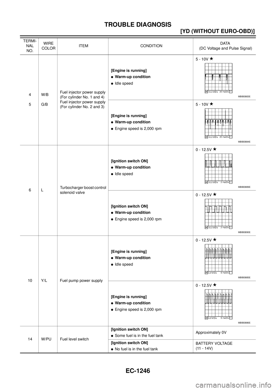
4
5W/B
G/BFuel injector power supply
(For cylinder No. 1 and 4)
Fuel injector power supply
(For cylinder No. 2 and 3)[Engine is running]
�Warm-up condition
�Idle speed5 - 10V
[Engine is running]
�Warm-up condition
�Engine speed is 2,000 rpm5 - 10V
6LTurbocharger boost control
solenoid valve[Ignition switch ON]
�Warm-up condition
�Idle speed0 - 12.5V
[Ignition switch ON]
�Warm-up condition
�Engine speed is 2,000 rpm0 - 12.5V
10 Y/L Fuel pump power supply[Engine is running]
�Warm-up condition
�Idle speed0 - 12.5V
[Engine is running]
�Warm-up condition
�Engine speed is 2,000 rpm0 - 12.5V
14 W/PU Fuel level switch[Ignition switch ON]
�Some fuel is in the fuel tankApproximately 0V
[Ignition switch ON]
�No fuel is in the fuel tankBATTERY VOLTAGE
(11 - 14V) TERMI-
NAL
NO.WIRE
COLORITEM CONDITIONDATA
(DC Voltage and Pulse Signal)
MBIB0883E
MBIB0884E
MBIB0889E
MBIB0890E
MBIB0885E
MBIB0886E
Page 1625 of 4179
![NISSAN X-TRAIL 2003 Service Repair Manual TROUBLE DIAGNOSIS
EC-1247
[YD (WITHOUT EURO-OBD)]
C
D
E
F
G
H
I
J
K
L
MA
EC
19 L Air conditioner relay[Engine is running]
�Air conditioner switch is OFFBATTERY VOLTAGE
(11 - 14V)
[Engine is running]](/manual-img/5/57404/w960_57404-1624.png "NISSAN X-TRAIL 2003 Service Repair Manual TROUBLE DIAGNOSIS
EC-1247
[YD (WITHOUT EURO-OBD)]
C
D
E
F
G
H
I
J
K
L
MA
EC
19 L Air conditioner relay[Engine is running]
�Air conditioner switch is OFFBATTERY VOLTAGE
(11 - 14V)
[Engine is running]")
TROUBLE DIAGNOSIS
EC-1247
[YD (WITHOUT EURO-OBD)]
C
D
E
F
G
H
I
J
K
L
MA
EC
19 L Air conditioner relay[Engine is running]
�Air conditioner switch is OFFBATTERY VOLTAGE
(11 - 14V)
[Engine is running]
�Both air conditioner switch and blower fan
switch are ON (Compressor is operating)Approximately 0.1V
21
22
23
24G/R
GY/L
G/R
GY/LFuel injector No. 2
Fuel injector No. 2
Fuel injector No. 3
Fuel injector No. 3[Engine is running]
�Warm-up condition
�Idle speed0 - 9V
[Engine is running]
�Warm-up condition
�Engine speed is 2,000 rpm0 - 9V
25
26
27
28GY
W/L
OR/B
GY/BEGR volume control valve[Engine is running]
�Warm-up condition
�Idle speed0.1 - 14V
(Voltage signals of each ECM ter-
minals differ according to the con-
trol position of EGR volume
control valve.)
29 L Fuel pump[Engine is running]
�Warm-up condition
�Idle speed0.5 - 1.0V
[Engine is running]
�Warm-up condition
�Engine speed is 2,000 rpm0.5 - 1.0V
34 LG/B Cooling fan relay (High)[Engine is running]
�Cooling fan is not operating
�Cooling fan is operating at low speedBATTERY VOLTAGE
(11 - 14V)
[Engine is running]
�Cooling fan is operating at high speedApproximately 0.1V
36 LG Cooling fan relay (Low)[Engine is running]
�Cooling fan is not operating
�Cooling fan is operating at high speedBATTERY VOLTAGE
(11 - 14V)
[Engine is running]
�Cooling fan is operating at low speedApproximately 0.1V TERMI-
NAL
NO.WIRE
COLORITEM CONDITIONDATA
(DC Voltage and Pulse Signal)
MBIB0881E
MBIB0882E
MBIB0887E
MBIB0888E
Page 1626 of 4179
EC-1248
[YD (WITHOUT EURO-OBD)]
TROUBLE DIAGNOSIS
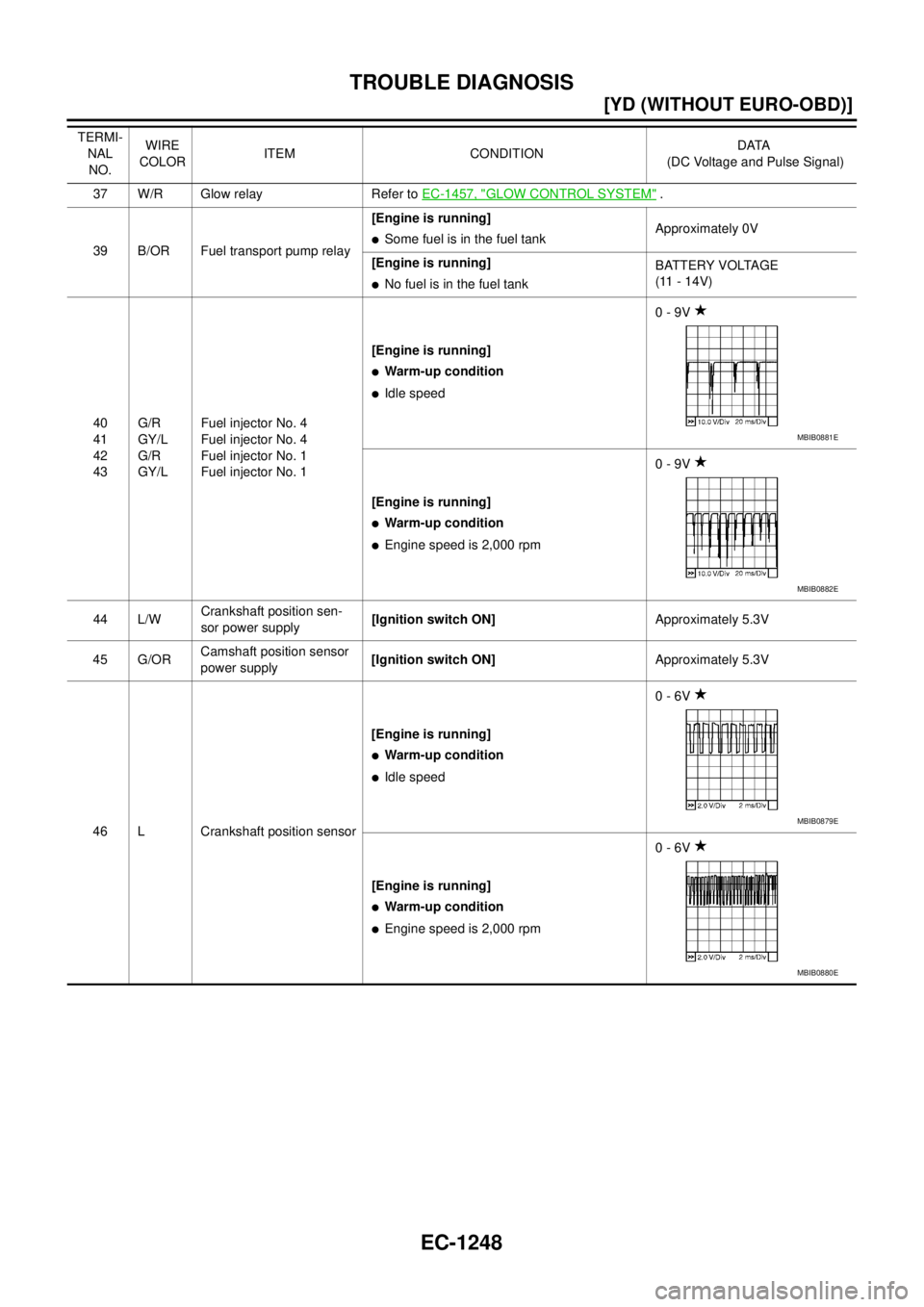
37 W/R Glow relay Refer to EC-1457, "GLOW CONTROL SYSTEM" .
39 B/OR Fuel transport pump relay[Engine is running]
�Some fuel is in the fuel tankApproximately 0V
[Engine is running]
�No fuel is in the fuel tankBATTERY VOLTAGE
(11 - 14V)
40
41
42
43G/R
GY/L
G/R
GY/LFuel injector No. 4
Fuel injector No. 4
Fuel injector No. 1
Fuel injector No. 1[Engine is running]
�Warm-up condition
�Idle speed0 - 9V
[Engine is running]
�Warm-up condition
�Engine speed is 2,000 rpm0 - 9V
44 L/WCrankshaft position sen-
sor power supply[Ignition switch ON]Approximately 5.3V
45 G/ORCamshaft position sensor
power supply[Ignition switch ON]Approximately 5.3V
46 L Crankshaft position sensor[Engine is running]
�Warm-up condition
�Idle speed0 - 6V
[Engine is running]
�Warm-up condition
�Engine speed is 2,000 rpm0 - 6V TERMI-
NAL
NO.WIRE
COLORITEM CONDITIONDATA
(DC Voltage and Pulse Signal)
MBIB0881E
MBIB0882E
MBIB0879E
MBIB0880E
Page 1627 of 4179
![NISSAN X-TRAIL 2003 Service Repair Manual TROUBLE DIAGNOSIS
EC-1249
[YD (WITHOUT EURO-OBD)]
C
D
E
F
G
H
I
J
K
L
MA
EC
47 G/R Camshaft position sensor[Engine is running]
�Warm-up condition
�Idle speed0 - 6V
[Engine is running]
�Warm-up cond](/manual-img/5/57404/w960_57404-1626.png "NISSAN X-TRAIL 2003 Service Repair Manual TROUBLE DIAGNOSIS
EC-1249
[YD (WITHOUT EURO-OBD)]
C
D
E
F
G
H
I
J
K
L
MA
EC
47 G/R Camshaft position sensor[Engine is running]
�Warm-up condition
�Idle speed0 - 6V
[Engine is running]
�Warm-up cond")
TROUBLE DIAGNOSIS
EC-1249
[YD (WITHOUT EURO-OBD)]
C
D
E
F
G
H
I
J
K
L
MA
EC
47 G/R Camshaft position sensor[Engine is running]
�Warm-up condition
�Idle speed0 - 6V
[Engine is running]
�Warm-up condition
�Engine speed is 2,000 rpm0 - 6V
48
49Y/R
RFuel rail pressure sensor[Engine is running]
�Warm-up condition
�Idle speed1.7 - 2.0V
[Engine is running]
�Warm-up condition
�Engine speed is 2,000 rpm2.0 - 2.3V
50 PUFuel pump temperature
sensor[Engine is running]
�Warm-up conditionApproximately 0.3 - 5.3V
Output voltage varies with fuel
pump temperature
51 L/OREngine coolant tempera-
ture sensor[Engine is running]
�Warm-up conditionApproximately 0.3 - 5.3V
Output voltage varies with engine
coolant temperature
52 Y Turbocharger boost sensor[Engine is running]
�Warm-up condition
�Idle speed2.3 - 2.6V
[Engine is running]
�Warm-up condition
�Engine speed is 2,000 rpm2.5 - 2.8V
54 W Mass air flow sensor[Engine is running]
�Warm-up condition
�Idle speed1.8 - 2.3V
[Engine is running]
�Warm-up condition
�Engine speed is 2,000 rpm2.5 - 3.0V
55 GIntake air temperature sen-
sor[Engine is running]
�Warm-up conditionApproximately 0.3 - 5.2V
Output voltage varies with intake
air temperature
59
60
61
62W/B
Y/B
G/B
R/BFuel injector adjustment
resistor No. 1
Fuel injector adjustment
resistor No. 3
Fuel injector adjustment
resistor No. 4
Fuel injector adjustment
resistor No. 2[Ignition switch ON]0.5 - 5.1V
(There are individual differences
between fuel injector adjustment
resistors.) TERMI-
NAL
NO.WIRE
COLORITEM CONDITIONDATA
(DC Voltage and Pulse Signal)
MBIB0877E
MBIB0878E
![NISSAN X-TRAIL 2003 Service Repair Manual TROUBLE DIAGNOSIS
EC-1239
[YD (WITHOUT EURO-OBD)]
C
D
E
F
G
H
I
J
K
L
MA
EC
Engine Control Component Parts LocationEBS011XH
PBIB1888E](/manual-img/5/57404/w960_57404-1616.png "NISSAN X-TRAIL 2003 Service Repair Manual TROUBLE DIAGNOSIS
EC-1239
[YD (WITHOUT EURO-OBD)]
C
D
E
F
G
H
I
J
K
L
MA
EC
Engine Control Component Parts LocationEBS011XH
PBIB1888E")