2003 NISSAN X-TRAIL wheel bolt torque
[x] Cancel search: wheel bolt torquePage 2766 of 3066
PS-6
STEERING WHEEL
STEERING WHEEL
PFP:48430
On-Vehicle Inspection and ServiceEGS0004E
PLAY INSPECTION
1. Turn steering wheel to straight-ahead position. Start engine and lightly turn steering wheel clockwise and
counter clockwise until front wheels start moving. Measure travel to starting point on circumference of
steering wheel.
2. If play is outside specifications, check following parts for proper installation: steering gear assembly, front
suspension, axles, and steering column
lCheck steering wheel for vertical, horizontal, or axial play.
lLift vehicle and check steering gear mounting bolts and nuts for looseness.
NEUTRAL POSITION INSPECTION
lAfter the wheel alignment inspection, carry out the neutral position inspection. Refer toWT-4.
lBefore removing steering wheel, check steering gear neutral position.
1. Set vehicle to straight-ahead position, and check that steering wheel is in neutral position.
2. If it is not in neutral position, remove steering wheel, and install again in properly.
3. If it is not adjusted within two teeth from center of gear, loosen tie rod lock nut. Then turn it to opposite
direction to adjust until amount of left and right becomes equal.
STEERING TORQUE CHECK
1. Stop vehicle on a dry flat paved road and apply parking brake.
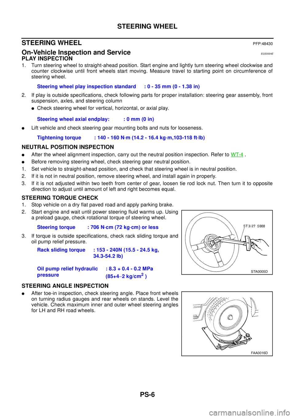
2. Start engine and wait until power steering fluid warms up. Using
a preload gauge, check rotational torque of steering wheel.
3. If torque is outside specifications, check rack sliding torque and
oil pump relief pressure.
STEERING ANGLE INSPECTION
lAfter toe-in inspection, check steering angle. Place front wheels
on turning radius gauges and rear wheels on stands. Level the
vehicle. Check maximum inner and outer wheel steering angles
for LH and RH road wheels.Steering wheel play inspection standard : 0 - 35 mm (0 - 1.38 in)
Steering wheel axial endplay: : 0 mm (0 in)
Tightening torque : 140 - 160 N·m (14.2 - 16.4 kg·m,103-118 ft·lb)
Steering torque : 706 N·cm (72 kg·cm) or less
Rack sliding torque : 153 - 240N (15.5 - 24.5 kg,
34.3-54.2 lb)
Oil pump relief hydraulic
pressure: 8.3 + 0.4 - 0.2 MPa
(85+4-2kg/cm
2)
STA0005D
FAA0016D
Page 2769 of 3066
STEERING COLUMN
PS-9
C
D
E
F
H
I
J
K
L
MA
B
PS
STEERING COLUMNPFP:48810
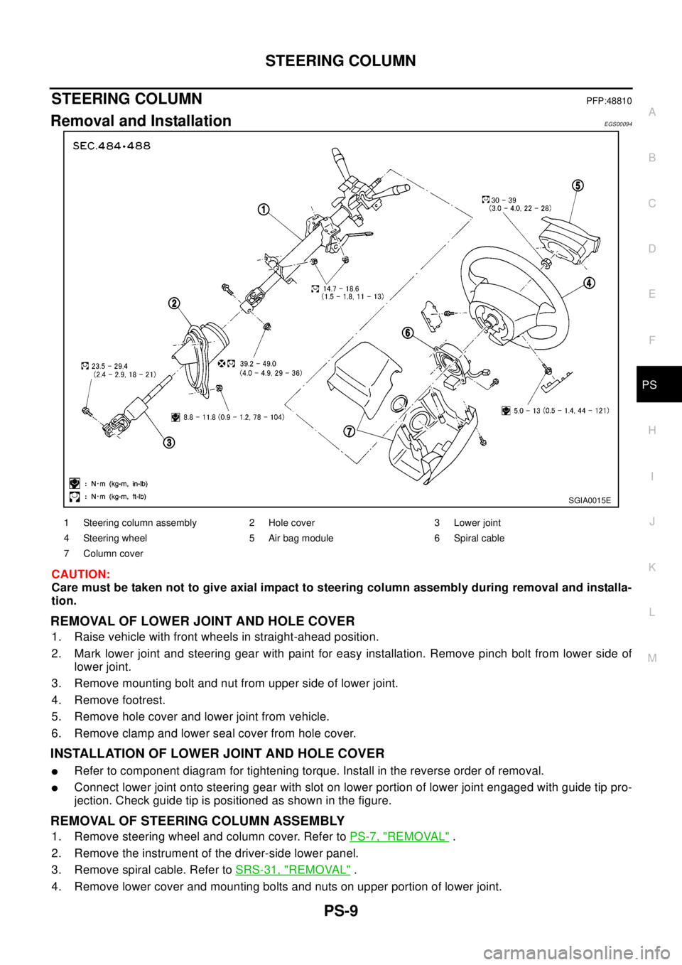
Removal and InstallationEGS00094
CAUTION:
Care must be taken not to give axial impact to steering column assembly during removal and installa-
tion.
REMOVAL OF LOWER JOINT AND HOLE COVER
1. Raise vehicle with front wheels in straight-ahead position.
2. Mark lower joint and steering gear with paint for easy installation. Remove pinch bolt from lower side of
lower joint.
3. Remove mounting bolt and nut from upper side of lower joint.
4. Remove footrest.
5. Remove hole cover and lower joint from vehicle.
6. Remove clamp and lower seal cover from hole cover.
INSTALLATION OF LOWER JOINT AND HOLE COVER
lRefer to component diagram for tightening torque. Install in the reverse order of removal.
lConnect lower joint onto steering gear with slot on lower portion of lower joint engaged with guide tip pro-
jection. Check guide tip is positioned as shown in the figure.
REMOVAL OF STEERING COLUMN ASSEMBLY
1. Remove steering wheel and column cover. Refer toPS-7, "REMOVAL".
2. Remove the instrument of the driver-side lower panel.
3. Remove spiral cable. Refer toSRS-31, "
REMOVAL".
4. Remove lower cover and mounting bolts and nuts on upper portion of lower joint.
SGIA0015E
1 Steering column assembly 2 Hole cover 3 Lower joint
4 Steering wheel 5 Air bag module 6 Spiral cable
7 Column cover
Page 2795 of 3066
SERVICE DATA AND SPECIFICATIONS (SDS)
PS-35
C
D
E
F
H
I
J
K
L
MA
B
PS
SERVICE DATA AND SPECIFICATIONS (SDS)PFP:00030
WheelEGS0004P
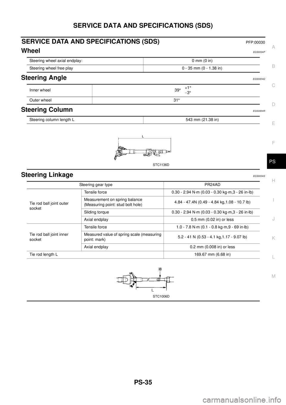
Steering AngleEGS0004Q
Steering ColumnEGS0004R
Steering LinkageEGS0004S
Steering wheel axial endplay: 0 mm (0 in)
Steering wheel free play 0 - 35 mm (0 - 1.38 in)
Inner wheel 39°+1°
-3°
Outer wheel 31°
Steering column length L 543 mm (21.38 in)
STC1136D
Steering gear type PR24AD
Tie rod ball joint outer
socketTensile force 0.30 - 2.94 N·m (0.03 - 0.30 kg·m,3 - 26 in-lb)
Measurement on spring balance
(Measuring point: stud bolt hole)4.84 - 47.4N (0.49 - 4.84 kg,1.08 - 10.7 lb)
Sliding torque 0.30 - 2.94 N·m (0.03 - 0.30 kg·m,3 - 26 in·lb)
Axial endplay 0.5 mm (0.02 in) or less
Tie rod ball joint inner
socketTensile force 1.0 - 7.8 N·m (0.1 - 0.8 kg·m,9 - 69 in·lb)
Measured value of spring scale (measuring
point: mark)5.2 - 41 N (0.53 - 4.1 kg,1.17 - 9.07 lb)
Axial endplay 0.2 mm (0.008 in) or less
Tie rod length L169.67 mm (6.68 in)
STC1006D
Page 2803 of 3066
WHEEL HUB (4WD)
RAX-7
C
E
F
G
H
I
J
K
L
MA
B
RAX
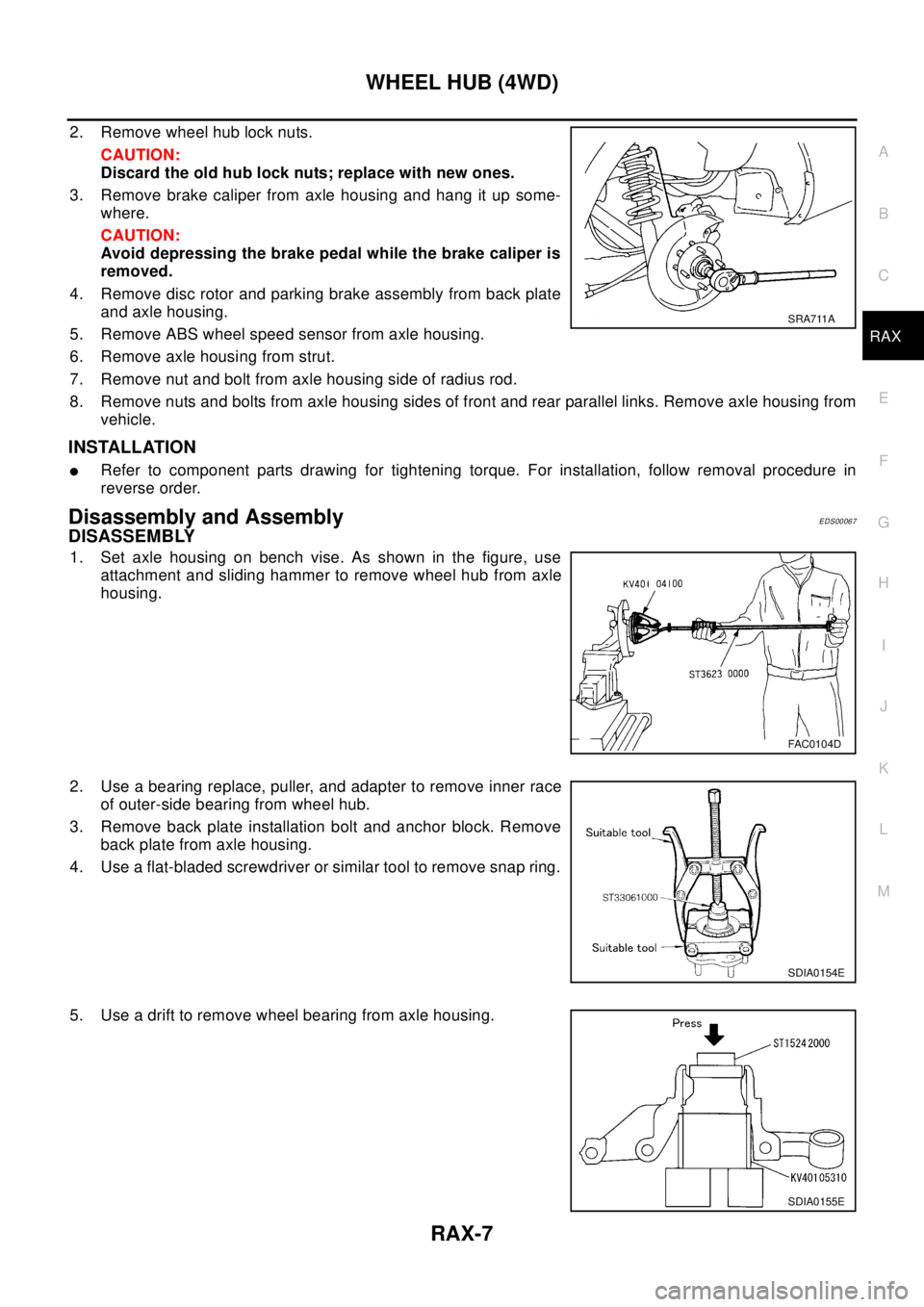
2. Remove wheel hub lock nuts.
CAUTION:
Discard the old hub lock nuts; replace with new ones.
3. Remove brake caliper from axle housing and hang it up some-
where.
CAUTION:
Avoid depressing the brake pedal while the brake caliper is
removed.
4. Remove disc rotor and parking brake assembly from back plate
andaxlehousing.
5. Remove ABS wheel speed sensor from axle housing.
6. Remove axle housing from strut.
7. Remove nut and bolt from axle housing side of radius rod.
8. Remove nuts and bolts from axle housing sides of front and rear parallel links. Remove axle housing from
vehicle.
INSTALLATION
lRefer to component parts drawing for tightening torque. For installation, follow removal procedure in
reverse order.
Disassembly and AssemblyEDS00067
DISASSEMBLY
1. Set axle housing on bench vise. As shown in the figure, use
attachment and sliding hammer to remove wheel hub from axle
housing.
2. Use a bearing replace, puller, and adapter to remove inner race
of outer-side bearing from wheel hub.
3. Remove back plate installation bolt and anchor block. Remove
back plate from axle housing.
4. Use a flat-bladed screwdriver or similar tool to remove snap ring.
5. Use a drift to remove wheel bearing from axle housing.
SRA711A
FAC0104D
SDIA0154E
SDIA0155E
Page 2804 of 3066
RAX-8
WHEEL HUB (4WD)
INSPECTION AFTER DISASSEMBLY
Wheel Hub
lInspect wheel hub for deformation, cracks, and other damage. If any irregular conditions are found,
replace wheel hub.
Axle Housing
lInspect axle housing for deformation, cracks, and other damage. If any irregular conditions are found,
replace axle housing.
Snap Ring
lCheck snap ring for deformation, cracks, and other damage. If any irregular conditions are found, replace
snap ring.
ASSEMBLY
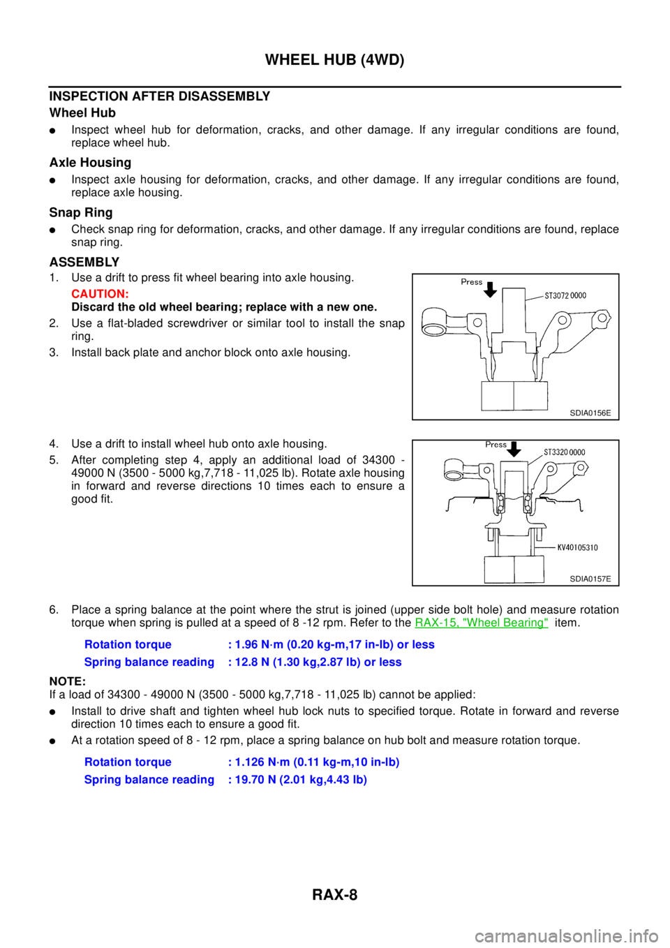
1. Use a drift to press fit wheel bearing into axle housing.
CAUTION:
Discard the old wheel bearing; replace with a new one.
2. Use a flat-bladed screwdriver or similar tool to install the snap
ring.
3. Install back plate and anchor block onto axle housing.
4. Use a drift to install wheel hub onto axle housing.
5. After completing step 4, apply an additional load of 34300 -
49000 N (3500 - 5000 kg,7,718 - 11,025 lb). Rotate axle housing
in forward and reverse directions 10 times each to ensure a
good fit.
6. Place a spring balance at the point where the strut is joined (upper side bolt hole) and measure rotation
torque when spring is pulled at a speed of 8 -12 rpm. Refer to theRAX-15, "
Wheel Bearing"item.
NOTE:
If a load of 34300 - 49000 N (3500 - 5000 kg,7,718 - 11,025 lb) cannot be applied:
lInstall to drive shaft and tighten wheel hub lock nuts to specified torque. Rotate in forward and reverse
direction 10 times each to ensure a good fit.
lAt a rotation speed of 8 - 12 rpm, place a spring balance on hub bolt and measure rotation torque.
SDIA0156E
SDIA0157E
Rotation torque : 1.96 N·m (0.20 kg-m,17 in-lb) or less
Spring balance reading : 12.8 N (1.30 kg,2.87 lb) or less
Rotation torque : 1.126 N·m (0.11 kg-m,10 in-lb)
Spring balance reading : 19.70 N (2.01 kg,4.43 lb)
Page 2824 of 3066
RFD-2
PRECAUTIONS
PRECAUTIONS
PFP:00001
CautionEDS00056
lBefore starting diagnosis of the vehicle, understand symptoms well. Perform correct and systematic oper-
ations.
lCheck for the correct installation status prior to removal or disassembly. When mating marks are required,
be sure they do not interfere with the function of the parts they are applied to.
lCarry out an overhaul in a clean work place. Using a dust proof room is recommended.
lBefore disassembly, using steam or white gasoline, completely remove sand and mud from the exterior of
the unit, preventing them from entering into the unit during disassembly or assembly.
lCheck appearance of the disassembled parts for damage, deformation, and abnormal wear. If a malfunc-
tion is detected, replace it with a new one.
lNormally replace lock pins, oil seals, and bearings with new ones every time they are removed.
lIn principle, tighten bolts or nuts gradually in several steps working diagonally from inside to outside. If
tightening sequence is specified, observe it.
lClean and flush the parts sufficiently and blow them dry.
lBe careful not to damage the sliding surfaces and mating surfaces.
lWhen applying sealant, remove the old sealant from the mounting surface; then remove any moisture, oil,
and foreign materials from the application and mounting surfaces.
lAlways use shop paper for cleaning the inside of components.
lAvoid using cotton gloves or a shop cloth to prevent entering of lint.
lDuring assembly, observe the specified tightening torque, and apply new differential oil, Vaseline, or Nis-
san MP Special Grease No. 2, as specified for each vehicle, when necessary.
lDo not reuse drained oil. Discard waste oil after oil changes or part treatment in accordance with local
laws and regulations.
Precautions for Brake SystemEDS000HX
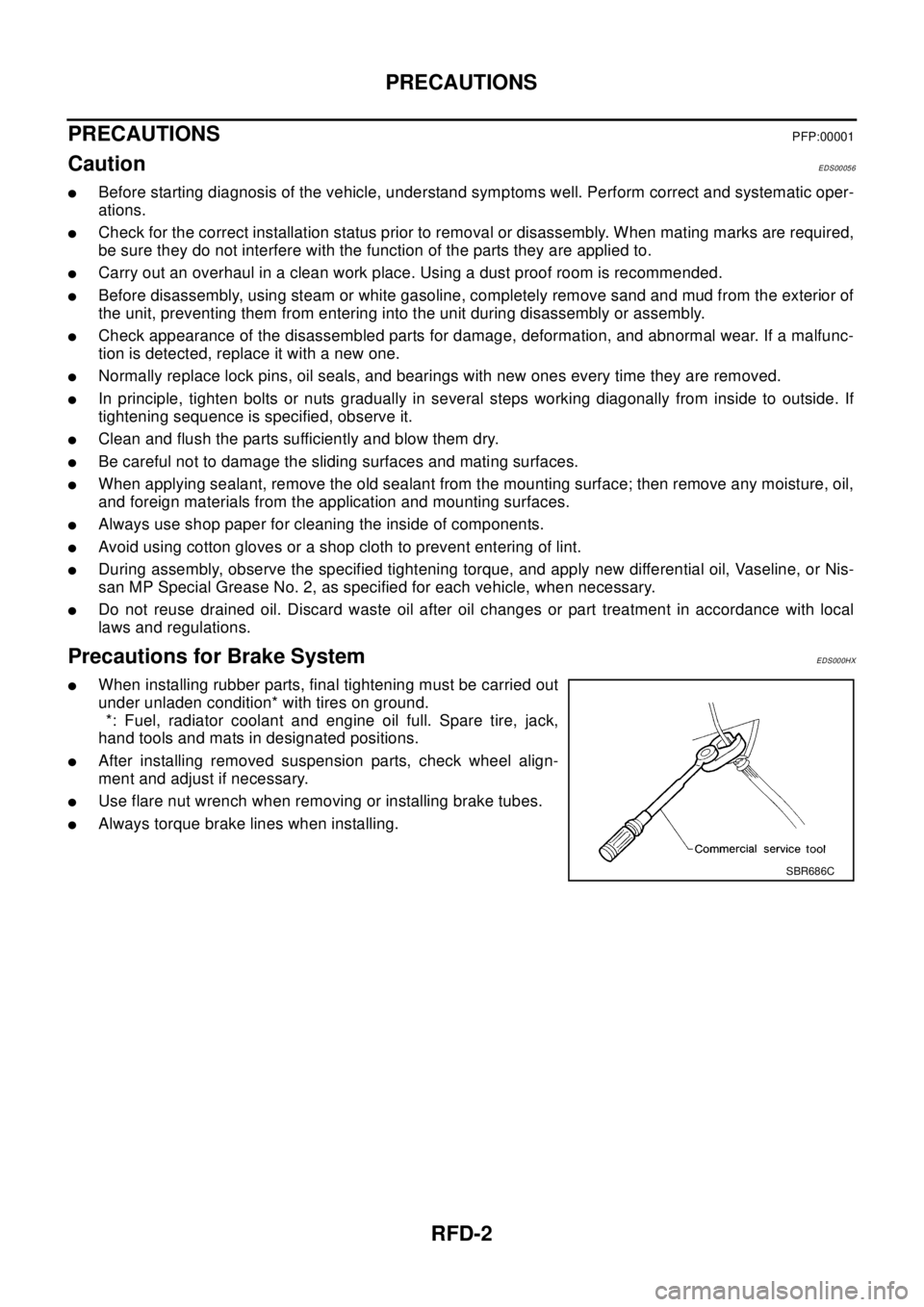
lWhen installing rubber parts, final tightening must be carried out
under unladen condition* with tires on ground.
*: Fuel, radiator coolant and engine oil full. Spare tire, jack,
hand tools and mats in designated positions.
lAfter installing removed suspension parts, check wheel align-
ment and adjust if necessary.
lUse flare nut wrench when removing or installing brake tubes.
lAlways torque brake lines when installing.
SBR686C
Page 2858 of 3066
RSU-6
REAR SUSPENSION ASSEMBLY
On-Vehicle Inspection and Service
EES0007F
Check axle and suspension parts for excessive play, wear, and damage.
lMove rear wheels (RH/LH) to check abnormal free play.
lRetighten all nuts and bolts to the specified torque.
lCheck strut for oil leakage and damage.
Wheel AlignmentEES0007G
DESCRIPTION
lMeasure wheel alignment under unladen conditions. “Unladen conditions” means that fuel, coolant, and
lubricant are full. However, spare tire, jack, and hand tools should be unloaded.
PRELIMINARY INSPECTION
1. Check the tires for improper air pressure and wear.
2. Check road wheels for runout.
3. Check wheel bearing axial endplay.
4. Check strut operation.
5. Check each mounting point of axle and suspension for looseness and deformation.
6. Check each link and arm for cracks, deformation, and other damage.
7. Check the vehicle posture.
CAMBER
Camber is preset at factory and cannot be adjusted.
lIf the camber is not within specification, inspect and replace any damaged or worn rear suspension parts.
TOE-IN
Measure toe-in using the following procedure.
lAlways perform following procedure on a flat surface.
lMake sure that no person is in front of the vehicle before push-
ing it.
1. Bounce rear of vehicle up and down to stabilize the posture.
2. Push the vehicle straight ahead about 5 m (16 ft).
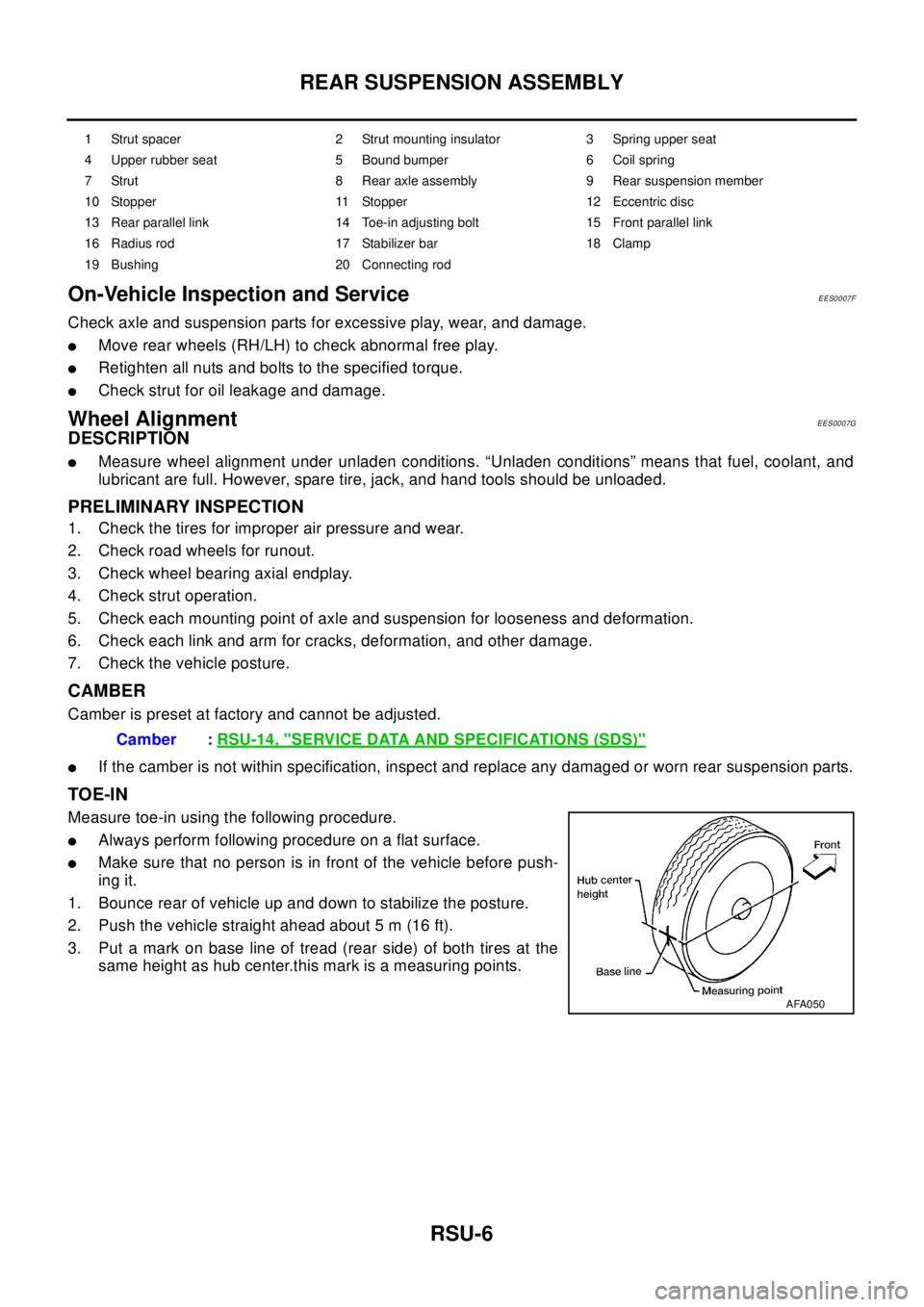
3. Put a mark on base line of tread (rear side) of both tires at the
same height as hub center.this mark is a measuring points.
1 Strut spacer 2 Strut mounting insulator 3 Spring upper seat
4 Upper rubber seat 5 Bound bumper 6 Coil spring
7 Strut 8 Rear axle assembly 9 Rear suspension member
10 Stopper 11 Stopper 12 Eccentric disc
13 Rear parallel link 14 Toe-in adjusting bolt 15 Front parallel link
16 Radius rod 17 Stabilizer bar 18 Clamp
19 Bushing 20 Connecting rod
Camber :RSU-14, "SERVICE DATA AND SPECIFICATIONS (SDS)"
AFA050
Page 2862 of 3066
RSU-10
FRONT PARALLEL LINK
FRONT PARALLEL LINK
PFP:55120
Removal and InstallationEES0007J
REMOVAL
1. Remove tires, Raise vehicle.
2. Remove ABS wheel speed sensor wire (With ABS models).
3. Remove front parallel link mounting bolts and nuts. Remove front parallel link from vehicle.
INSPECTION AFTER REMOVAL
lReplace front parallel link assembly if it is in following condition: deformed, cracked, or damaged, or if the
bushing was damaged.
INSTALLATION
lRefer toRSU-5, "Components"for tightening torque and reverse the removal procedure for installation.