2003 NISSAN X-TRAIL wheel bolt torque
[x] Cancel search: wheel bolt torquePage 987 of 3066
![NISSAN X-TRAIL 2003 Electronic Repair Manual WHEEL SPEED SENSORS
BRC-119
[ESP/TCS/ABS]
C
D
E
G
H
I
J
K
L
MA
B
BRC
WHEEL SPEED SENSORSPFP:47910
Removal and InstallationEFS001CD
CAUTION:
lBe careful not to damage sensor edge and rotor tooth. Befor NISSAN X-TRAIL 2003 Electronic Repair Manual WHEEL SPEED SENSORS
BRC-119
[ESP/TCS/ABS]
C
D
E
G
H
I
J
K
L
MA
B
BRC
WHEEL SPEED SENSORSPFP:47910
Removal and InstallationEFS001CD
CAUTION:
lBe careful not to damage sensor edge and rotor tooth. Befor](/manual-img/5/57402/w960_57402-986.png)
WHEEL SPEED SENSORS
BRC-119
[ESP/TCS/ABS]
C
D
E
G
H
I
J
K
L
MA
B
BRC
WHEEL SPEED SENSORSPFP:47910
Removal and InstallationEFS001CD
CAUTION:
lBe careful not to damage sensor edge and rotor tooth. Before removing front or rear wheel hub,
remove wheel speed sensor to avoid sensor wiring damage. Otherwise, sensor may be deacti-
vated.
lWhen removing sensor, avoid rotating it as much as possible. Do not forcibly pull sensor harness.
lWhen installing, check sensor pick-up and mounting hole for foreign material such as iron chips.
Check no foreign material has been caught in sensor rotor. Remove any foreign material found.
Tighten mounting bolts and nuts to the specified torque.
SFIA0042E
Page 1008 of 3066

CL-16
CLUTCH DISC, CLUTCH COVER AND FLYWHEEL
Clutch cover
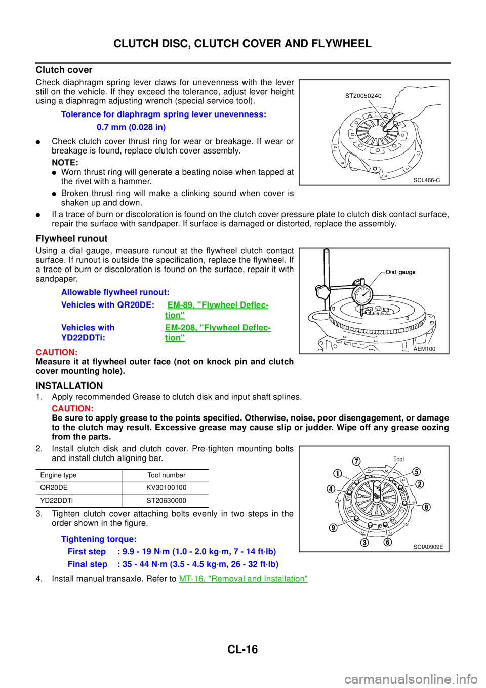
Check diaphragm spring lever claws for unevenness with the lever
still on the vehicle. If they exceed the tolerance, adjust lever height
using a diaphragm adjusting wrench (special service tool).
lCheck clutch cover thrust ring for wear or breakage. If wear or
breakage is found, replace clutch cover assembly.
NOTE:
lWorn thrust ring will generate a beating noise when tapped at
therivetwithahammer.
lBroken thrust ring will make a clinking sound when cover is
shaken up and down.
lIf a trace of burn or discoloration is found on the clutch cover pressure plate to clutch disk contact surface,
repair the surface with sandpaper. If surface is damaged or distorted, replace the assembly.
Flywheel runout
Using a dial gauge, measure runout at the flywheel clutch contact
surface. If runout is outside the specification, replace the flywheel. If
a trace of burn or discoloration is found on the surface, repair it with
sandpaper.
CAUTION:
Measure it at flywheel outer face (not on knock pin and clutch
cover mounting hole).
INSTALLATION
1. Apply recommended Grease to clutch disk and input shaft splines.
CAUTION:
Be sure to apply grease to the points specified. Otherwise, noise, poor disengagement, or damage
to the clutch may result. Excessive grease may cause slip or judder. Wipe off any grease oozing
from the parts.
2. Install clutch disk and clutch cover. Pre-tighten mounting bolts
and install clutch aligning bar.
3. Tighten clutch cover attaching bolts evenly in two steps in the
order shown in the figure.
4. Install manual transaxle. Refer toMT-16, "
Removal and Installation"
Tolerance for diaphragm spring lever unevenness:
0.7 mm (0.028 in)
SCL466-C
Allowable flywheel runout:
Vehicles with QR20DE:EM-89, "
Flywheel Deflec-
tion"
Vehicles with
YD22DDTi:EM-208, "Flywheel Deflec-
tion"
AEM100
Engine type Tool number
QR20DE KV30100100
YD22DDTi ST20630000
Tightening torque:
First step : 9.9 - 19 N·m (1.0 - 2.0 kg·m, 7 - 14 ft·lb)
Final step : 35 - 44 N·m (3.5 - 4.5 kg·m, 26 - 32 ft·lb)SCIA0909E
Page 1972 of 3066

EM-2
INSPECTION AFTER REMOVAL ........................ 38
Valve Clearance ...................................................... 40
INSPECTION ....................................................... 40
ADJUSTMENT .................................................... 41
TIMING CHAIN .......................................................... 43
Removal and Installation ........................................ 43
REMOVAL ........................................................... 44
INSPECTION AFTER REMOVAL ........................ 47
INSTALLATION .................................................... 48
CYLINDER HEAD ..................................................... 52
On-Vehicle Service ................................................. 52
CHECKING COMPRESSION PRESSURE ......... 52
Removal and Installation ........................................ 53
REMOVAL ........................................................... 53
INSPECTION AFTER REMOVAL ........................ 54
INSTALLATION .................................................... 54
Disassembly and Assembly .................................... 55
DISASSEMBLY ................................................... 55
ASSEMBLY ......................................................... 56
Inspection After Disassembly ................................. 56
CYLINDER HEAD DISTORTION ........................ 56
VALVE DIMENSIONS .......................................... 57
VALVE GUIDE CLEARANCE .............................. 57
VALVE GUIDE REPLACEMENT ......................... 57
VALVE SEAT CONTACT ..................................... 58
VALVE SEAT REPLACEMENT ........................... 58
VALVE SPRING SQUARENESS ......................... 60
VALVE SPRING DIMENSIONS AND VALVE
SPRING PRESSURE LOAD ............................... 60
ENGINE ASSEMBLY ................................................ 61
Removal and Installation ........................................ 61
REMOVAL ........................................................... 61
INSTALLATION .................................................... 63
INSPECTION AFTER INSTALLATION ................ 63
CYLINDER BLOCK ................................................... 64
Disassembly and Assembly .................................... 64
DISASSEMBLY ................................................... 65
ASSEMBLY ......................................................... 69
How to Select Piston and Bearing .......................... 73
DESCRIPTION .................................................... 73
HOW TO SELECT PISTON ................................. 74
HOW TO SELECT CONNCTING ROD BEARING... 74
HOW TO SELECT MAIN BEARING .................... 77
Inspection After Disassembly ................................. 80
CRANKSHAFT SIDE CLEARANCE .................... 80
CONNECTING ROD SIDE CLEARANCE ........... 81
PISTON AND PISTON PIN CLEARANCE .......... 81
PISTON RING SIDE CLEARANCE ..................... 82
PISTON RING END GAP .................................... 82
CONNECTING ROD BEND AND TORSION ....... 82
CONNECTING ROD BEARING (BIG END) ........ 83
CONNECTING ROD BUSHING OIL CLEAR-
ANCE (SMALL END) ........................................... 83
CYLINDER BLOCK DISTORTION ...................... 84
INNER DIAMETER OF MAIN BEARING HOUS-
ING ...................................................................... 85
PISTON TO CYLINDER BORE CLEARANCE .... 85
OUTER DIAMETER OF CRANKSHAFT JOUR-NAL ......................................................................86
OUTER DIAMETER OF CRANKSHAFT PIN ......86
OUT-OF-ROUND AND TAPER OF CRANK-
SHAFT .................................................................87
CRANKSHAFT RUNOUT ....................................87
OIL CLEARANCE OF CONNECTING ROD
BEARING .............................................................87
OIL CLEARANCE OF MAIN BEARING ...............88
CRUSH HEIGH OF MAIN BEARING ...................88
OUTER DIAMETER OF LOWER CYLINDER
BLOCK MOUNTING BOLT ..................................88
OUTER DIAMETER OF CONNECTING ROD
BOLT ....................................................................89
MOVEMENT AMOUNT OF FLYWHEEL (M/T
MODELS) .............................................................89
SERVICE DATA AND SPECIFICATIONS (SDS) ......90
Standard and Limit ..................................................90
GENERAL SPECIFICATIONS .............................90
INTAKE MANIFOLD AND EXHAUST MANI-
FOLD ...................................................................90
DRIVE BELTS ......................................................90
CYLINDER HEAD ................................................91
VALVE ..................................................................91
CAMSHAFT AND CAMSHAFT BEARING ...........94
CYLINDER BLOCK ..............................................94
PISTON, PISTON RING AND PISTON PIN ........95
CONNECTING ROD ............................................96
CRANKSHAFT .....................................................97
MAIN BEARING ...................................................98
CONNECTING ROD BEARING ...........................99
Tightening Torque ................................................. 100
YD22DDTi
PRECAUTIONS ....................................................... 102
Precautions for Drain Coolant ............................... 102
Precautions for Disconnecting Fuel Piping ........... 102
Precautions for Removal and Disassembly .......... 102
Precautions for Inspection, Repair and Replace-
ment ...................................................................... 102
Precautions for Assembly and Installation ............ 102
Parts Requiring Angular Tightening ...................... 102
Precautions for Liquid Gasket ............................... 103
REMOVAL OF LIQUID GASKET SEALING ...... 103
LIQUID GASKET APPLICATION PROCEDURE. 103
PREPARATION ....................................................... 104
Special Service Tools ............................................ 104
Commercial Service Tools .................................... 106
NOISE, VIBRATION, AND HARSHNESS (NVH)
TROUBLESHOOTING ............................................ 108
NVH Troubleshooting —Engine Noise .................. 108
Use the Chart Below to Help You Find the Cause
of the Symptom. .................................................... 109
DRIVE BELTS ..........................................................110
Checking Drive Belts .............................................110
Tension Adjustment ...............................................110
AIR CONDITIONER COMPRESSOR BELT ...... 111
Page 1974 of 3066

EM-4
HOW TO SELECT MAIN BEARING ..................199
Inspection After Disassembly ...............................200
CRANKSHAFT SIDE CLEARANCE ..................200
CONNECTING ROD SIDE CLEARANCE .........200
PISTON TO PISTON PIN CLEARANCE ...........201
PISTON RING SIDE CLEARANCE ...................201
PISTON RING END GAP ..................................202
CONNECTING ROD BEND AND TORSION .....202
CONNECTING ROD BIG END INNER DIAME-
TER ...................................................................202
CONNECTING ROD BUSHING OIL CLEAR-
ANCE (SMALL END) .........................................203
CYLINDER BLOCK TOP SURFACE DISTOR-
TION ..................................................................203
MAIN BEARING HOUSING INNER DIAMETER. 204
PISTON TO CYLINDER BORE CLEARANCE ..204
CRANKSHAFT JOURNAL OUTER DIAMETER. 205
CRANKSHAFT PIN OUTER DIAMETER ..........205
CRANKSHAFT OUT-OF-ROUND AND TAPER. 205
CRANKSHAFT RUNOUT ..................................206
CONNECTING ROD BEARING OIL CLEAR-ANCE ................................................................. 206
MAIN BEARING OIL CLEARANCE ................... 206
MAIN BEARING CRUSH HETIGH .................... 207
MAIN BEARING CAP BOLT DEFORMATION ... 207
CONNECTING ROD BOLT DEFORMATION .... 207
OIL JET .............................................................. 208
OIL JET RELIEF VALVE .................................... 208
MOVEMENT AMOUNT OF FLYWHEEL ........... 208
SERVICE DATA AND SPECIFICATIONS (SDS) .... 210
Standard and Limit ................................................ 210
GENERAL SPECIFICATIONS ........................... 210
INTAKE MANIFOLD AND EXHAUST MANI-
FOLD ................................................................. 210
DRIVE BELTS .................................................... 210
CYLINDER HEAD ..............................................211
VALVE ................................................................211
CAMSHAFT AND CAMSHAFT BEARING ......... 215
CYLINDER BLOCK ............................................ 215
PISTON, PISTON RING AND PISTON PIN ...... 216
CONNCTING ROD ............................................ 217
CRANKSHAFT ................................................... 217
AVAILABLE MAIN BEARING ............................. 218
AVAILABLE CONNECTING ROD BEARING ..... 218
MISCELLANEOUS COMPONENTS .................. 219
Tightening Torque ................................................. 219
Page 2059 of 3066
![NISSAN X-TRAIL 2003 Electronic Repair Manual CYLINDER BLOCK
EM-89
[QR20DE]
C
D
E
F
G
H
I
J
K
L
MA
EM
OUTER DIAMETER OF CONNECTING ROD BOLT
lMeasure outer diameter (d) at position shown in the figure.
lWhen “d ” exceeds the limit (when it bec NISSAN X-TRAIL 2003 Electronic Repair Manual CYLINDER BLOCK
EM-89
[QR20DE]
C
D
E
F
G
H
I
J
K
L
MA
EM
OUTER DIAMETER OF CONNECTING ROD BOLT
lMeasure outer diameter (d) at position shown in the figure.
lWhen “d ” exceeds the limit (when it bec](/manual-img/5/57402/w960_57402-2058.png)
CYLINDER BLOCK
EM-89
[QR20DE]
C
D
E
F
G
H
I
J
K
L
MA
EM
OUTER DIAMETER OF CONNECTING ROD BOLT
lMeasure outer diameter (d) at position shown in the figure.
lWhen “d ” exceeds the limit (when it becomes thinner), replace
the bolt with a new one.
MOVEMENT AMOUNT OF FLYWHEEL (M/T MODELS)
NOTE:
lInspection for double mass flywheel only.
lDo not disassembly double mass flywheel.
Flywheel Deflection
lMeasure deflection of flywheel contact surface to the clutch with a dial gauge.
lMeasure deflection at 210 mm (8.27 in) dia.
lWhen measured value exceeds the limit, replace it with a new
one.
Movement Amount in Radial (rotation) Direction
lCheck the movement amount in the following procedure.
1. Install a bolt to clutch cover mounting hole, and place a torque wrench on the extended line of the flywheel
center line.
lTighten bolt at a force of 9.8 N·m (1kg-m, 87 in-lb) to keep it from loosening.
2. Put a mating mark on circumferences of the two flywheel
masses without applying any load (Measurement standard
points).
3. Apply a force of 9.8 N·m (1kg-m, 87 in-lb) in each direction, and
mark the movement amount on the mass on the transmission
side.
4. Measure dimensions of movement amounts A and B on circum-
ference of the flywheel on the transmission side.
lWhen measured value is outside the standard, replace flywheel.Limit : 7.75 mm (0.3051in) or less.
PBIC0273E
Standard : 0.45mm (0.0177in)or less
Limit : 1.3mm (0.051in) or less
PBIC0274E
Standard : 28.3mm (1.114in) or less
KBIA0297E
Page 2178 of 3066
![NISSAN X-TRAIL 2003 Electronic Repair Manual EM-208
[YD22DDTi]
CYLINDER BLOCK
OIL JET
lCheck nozzle for deformation and damage.
lBlow compressed air from nozzle, and check for clogs.
lIf it out of the standard, replace oil jet.
OIL JET RELIEF VA NISSAN X-TRAIL 2003 Electronic Repair Manual EM-208
[YD22DDTi]
CYLINDER BLOCK
OIL JET
lCheck nozzle for deformation and damage.
lBlow compressed air from nozzle, and check for clogs.
lIf it out of the standard, replace oil jet.
OIL JET RELIEF VA](/manual-img/5/57402/w960_57402-2177.png)
EM-208
[YD22DDTi]
CYLINDER BLOCK
OIL JET
lCheck nozzle for deformation and damage.
lBlow compressed air from nozzle, and check for clogs.
lIf it out of the standard, replace oil jet.
OIL JET RELIEF VALVE
lUsing a clean plastic stick, press check valve in oil jet relief
valve. Make sure that valve moves smoothly with proper reac-
tion force.
lIf it is out of the standard, replace oil jet relief valve.
MOVEMENT AMOUNT OF FLYWHEEL
NOTE:
lInspection for double mass flywheel only.
lDo not disassembly double mass flywheel.
Flywheel Deflection
lMeasure deflection of flywheel contact surface to the clutch with a dial gauge.
lMeasure deflection at 210 mm (8.27 in) dia.
lWhen measured value exceeds the limit, replace flywheel with a
new one.
Movement Amount in Radial (rotation) Direction
lCheck the movement amount in the following procedure.
1. Install a bolt to clutch cover mounting hole, and place a torque wrench on the extended line of the flywheel
center line.
lTighten bolt at a force of 9.8 N·m (1kg-m, 87 in-lb) to keep it from loosening.Standard : Deformation and damage.
JEM221G
Standard
: Valve moves smoothly with proper reaction force.
JEM222G
Standard : 0.45mm (0.0177 in) or less
Limit : 1.3mm (0.051 in)
PBIC0274E
Page 2189 of 3066
![NISSAN X-TRAIL 2003 Electronic Repair Manual SERVICE DATA AND SPECIFICATIONS (SDS)
EM-219
[YD22DDTi]
C
D
E
F
G
H
I
J
K
L
MA
EM
MISCELLANEOUS COMPONENTS
Flywheel
Unit: mm (in)
*: Total indicator reading
Bearing Clearance
Unit: mm (in)
Tightening NISSAN X-TRAIL 2003 Electronic Repair Manual SERVICE DATA AND SPECIFICATIONS (SDS)
EM-219
[YD22DDTi]
C
D
E
F
G
H
I
J
K
L
MA
EM
MISCELLANEOUS COMPONENTS
Flywheel
Unit: mm (in)
*: Total indicator reading
Bearing Clearance
Unit: mm (in)
Tightening](/manual-img/5/57402/w960_57402-2188.png)
SERVICE DATA AND SPECIFICATIONS (SDS)
EM-219
[YD22DDTi]
C
D
E
F
G
H
I
J
K
L
MA
EM
MISCELLANEOUS COMPONENTS
Flywheel
Unit: mm (in)
*: Total indicator reading
Bearing Clearance
Unit: mm (in)
Tightening TorqueEBS00BPP
*1: Parts to be tightened in particular orders.
1)-: Order of tightening when tightening two or more times separately.
Unit: N·m (kg-m, ft-lb)
Unit: N·m (kg-m, in-lb)*2
Flywheel runout [TIR]*Standard 0.45 (0.0177) or less
Limit 1.3 (0.051) or less
Main bearing clearanceStandard 0.039 - 0.066 (0.0015 - 0.0026)
Limit 0.10 (0.0039)
Connecting rod bearing clear-
anceStandard 0.031 - 0.061 (0.0012 - 0.0024)
Limit 0.09 (0.0035)
Alternator Nut C 19 - 24 (1.9 - 2.5, 14 - 18)
Nut D 44 - 57 (4.4 - 5.9, 32 - 42)
Idler pulely Nut A 31 - 39 (3.1 - 4.0, 23 - 28 )
Catalyst44 - 53 (4.4 - 5.5 , 32 - 39)
Catalyst rear diffuser30 - 37 (3.0 - 3.8 ,22 - 27 )
Catalyst insulator
6.4 - 8.3 (0.65 - 0.85, 57 - 73)*
2
Turbocharger44.0 - 53.0 (4.4 - 5.5, 32 -39 )
Charge air cooler19.6 - 23.5( 2.0 - 2.3,15 - 17 )
Charge air cooler cover
6.37 - 7.45( 0.65 - 0.75 ,57- 65)*
2
EGR volume control valve 62.0 - 78.0 (6.3 - 8.0, 46 - 57)
EGR tube60.0 - 69.0 (6.1 - 7.1, 45 - 51)
EGR support21.0 - 26.0 (2.1 - 2.7, 16 - 19)
Exhaust manifold insulator
5.1 - 6.4 (0.52 - 0.66, 46 - 57)*
2
*1 Exhaust manifold29.0- 33.0 (2.9 - 3.4, 21 - 24)
*1 Rocker cover1)
6.8 - 8.8 (0.7 - 0.9, 61 - 75)*
2
2)
6.8 - 8.8 (0.7 - 0.9, 61 - 75) *2
Oil pan lower
6.4 - 7.5 (0.65 - 0.76, 57 - 66)*2
Oil pan drain plug29.4 - 39.2 (3.0 - 4.0, 22 - 28)
Oil strainer15.7 - 18.6 (1.6 - 1.9, 12 - 13)
*1 Oil pan upper M6 bolt
6.4 - 7.5 (0.65 - 0.76 ,57 - 66 )*
2
M8 bolt 19.6 - 23.5 (2.0 - 2.4, 15 - 17)
M10 bolt 30.4 - 36.3,(3.1 - 3.7 , 23 - 26 )
Vacuum pump32.0 - 42.0 (3.3 - 4.3, 24 - 30)
Cylinder head rear cover M6 bolt
8.4 - 11.0 (0.86 - 1.1, 75 - 97) *
2
Page 2203 of 3066

FRONT WHEEL HUB AND KNUCKLE
FAX-7
C
E
F
G
H
I
J
K
L
MA
B
FA X
FRONT WHEEL HUB AND KNUCKLEPFP:40202
On-Vehicle InspectionEDS0005R
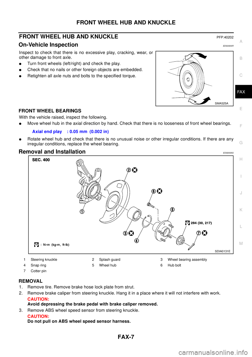
Inspect to check that there is no excessive play, cracking, wear, or
other damage to front axle.
lTurn front wheels (left/right) and check the play.
lCheck that no nails or other foreign objects are embedded.
lRetighten all axle nuts and bolts to the specified torque.
FRONT WHEEL BEARINGS
With the vehicle raised, inspect the following.
lMove wheel hub in the axial direction by hand. Check that there is no looseness of front wheel bearings.
lRotate wheel hub and check that there is no unusual noise or other irregular conditions. If there are any
irregular conditions, replace the wheel bearing.
Removal and InstallationEDS0005S
REMOVAL
1. Remove tire. Remove brake hose lock plate from strut.
2. Remove brake caliper from steering knuckle. Hang it in a place where it will not interfere with work.
CAUTION:
Avoid depressing the brake pedal with brake caliper removed.
3. Remove ABS wheel speed sensor from steering knuckle.
CAUTION:
Do not pull on ABS wheel speed sensor harness.
SMA525A
Axial end play : 0.05 mm (0.002 in)
SDIA0131E
1 Steering knuckle 2 Splash guard 3 Wheel bearing assembly
4 Snap ring 5 Wheel hub 6 Hub bolt
7Cotterpin