Page 2886 of 3066

SC-14
CHARGING SYSTEM
Trouble Diagnoses
EKS00319
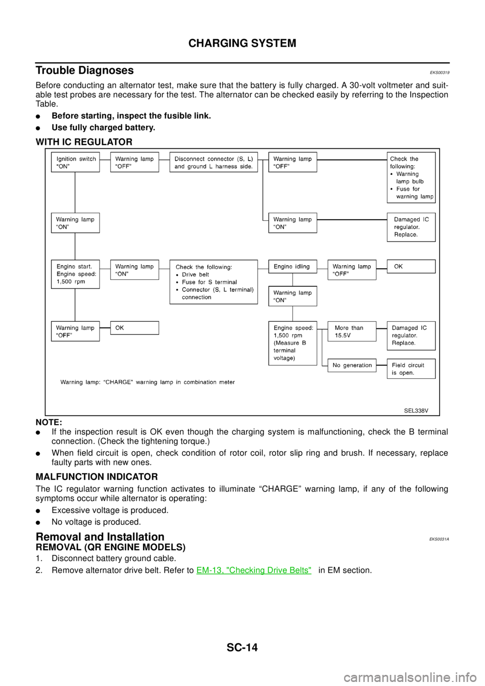
Before conducting an alternator test, make sure that the battery is fully charged. A 30-volt voltmeter and suit-
able test probes are necessary for the test. The alternator can be checked easily by referring to the Inspection
Table.
lBefore starting, inspect the fusible link.
lUse fully charged battery.
WITH IC REGULATOR
NOTE:
lIf the inspection result is OK even though the charging system is malfunctioning, check the B terminal
connection. (Check the tightening torque.)
lWhen field circuit is open, check condition of rotor coil, rotor slip ring and brush. If necessary, replace
faulty parts with new ones.
MALFUNCTION INDICATOR
The IC regulator warning function activates to illuminate “CHARGE” warning lamp, if any of the following
symptoms occur while alternator is operating:
lExcessive voltage is produced.
lNo voltage is produced.
Removal and InstallationEKS0031A
REMOVAL (QR ENGINE MODELS)
1. Disconnect battery ground cable.
2. Remove alternator drive belt. Refer toEM-13, "
Checking Drive Belts"in EM section.
SEL338V
Page 2887 of 3066

CHARGING SYSTEM
SC-15
C
D
E
F
G
H
I
J
L
MA
B
SC
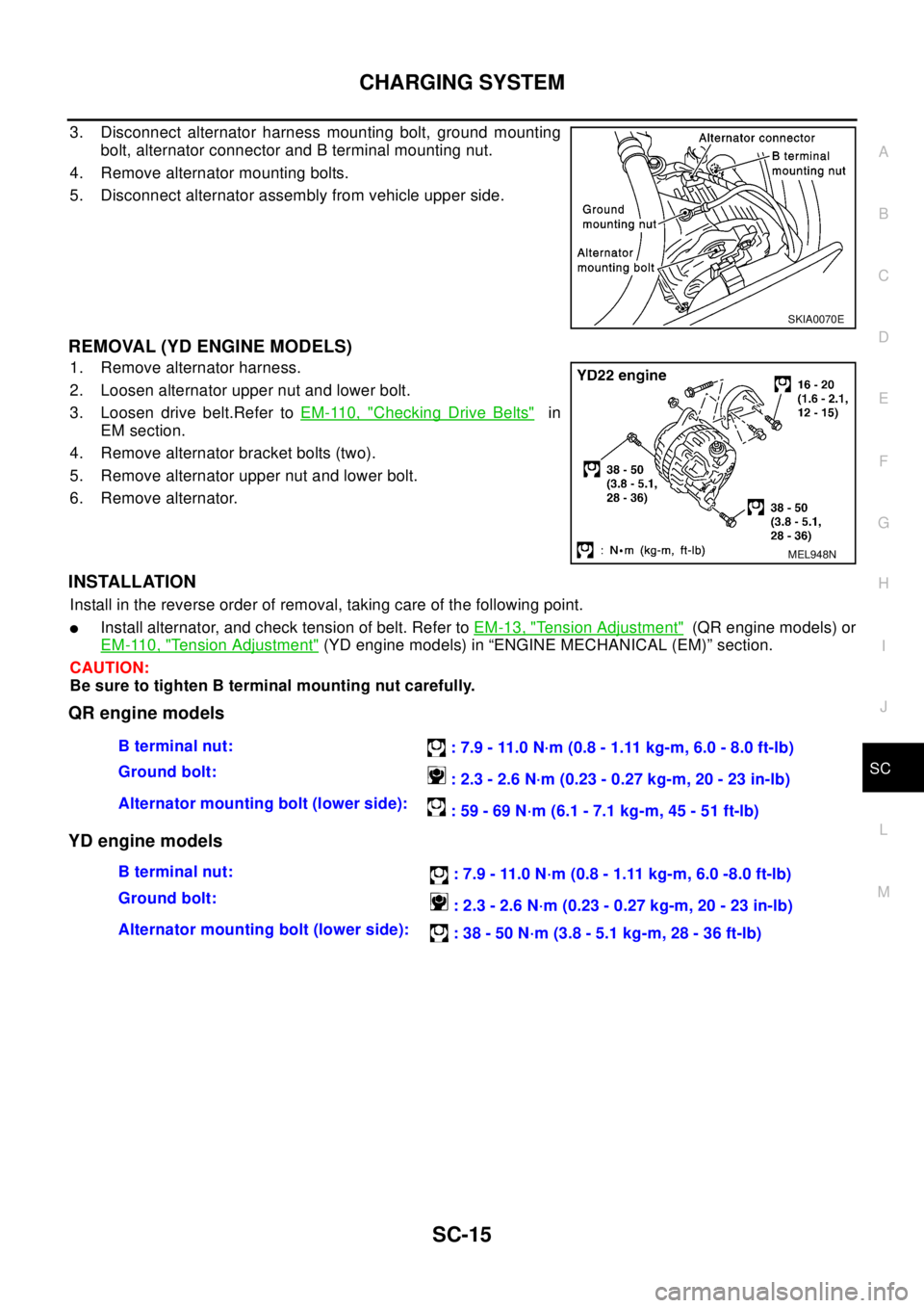
3. Disconnect alternator harness mounting bolt, ground mounting
bolt, alternator connector and B terminal mounting nut.
4. Remove alternator mounting bolts.
5. Disconnect alternator assembly from vehicle upper side.
REMOVAL (YD ENGINE MODELS)
1. Remove alternator harness.
2. Loosen alternator upper nut and lower bolt.
3. Loosen drive belt.Refer toEM-110, "
Checking Drive Belts"in
EM section.
4. Remove alternator bracket bolts (two).
5. Remove alternator upper nut and lower bolt.
6. Remove alternator.
INSTALLATION
Install in the reverse order of removal, taking care of the following point.
lInstall alternator, and check tension of belt. Refer toEM-13, "Tension Adjustment"(QR engine models) or
EM-110, "
Tension Adjustment"(YD engine models) in “ENGINE MECHANICAL (EM)” section.
CAUTION:
Be sure to tighten B terminal mounting nut carefully.
QR engine models
YD engine models
SKIA0070E
MEL948N
Bterminalnut:
: 7.9 - 11.0 N·m (0.8 - 1.11 kg-m, 6.0 - 8.0 ft-lb)
Ground bolt:
:2.3-2.6N·m(0.23-0.27kg-m,20-23in-lb)
Alternator mounting bolt (lower side):
: 59 - 69 N·m (6.1 - 7.1 kg-m, 45 - 51 ft-lb)
Bterminalnut:
: 7.9 - 11.0 N·m (0.8 - 1.11 kg-m, 6.0 -8.0 ft-lb)
Ground bolt:
: 2.3 - 2.6 N·m (0.23 - 0.27 kg-m, 20 - 23 in-lb)
Alternator mounting bolt (lower side):
: 38 - 50 N·m (3.8 - 5.1 kg-m, 28 - 36 ft-lb)
Page 2890 of 3066

SC-18
CHARGING SYSTEM
CAUTION:
Rear cover may be hard to remove because a ring is used to lock outer race of rear bearing. To facili-
tate removal of rear cover, heat just bearing box section with a 200W soldering iron.
Do not use a heat gun, as it can damage diode assembly.
REAR BEARING
CAUTION:
lDo not reuse rear bearing after removal. Replace with a new one.
lDo not lubricate rear bearing outer race.
InspectionEKS0031D
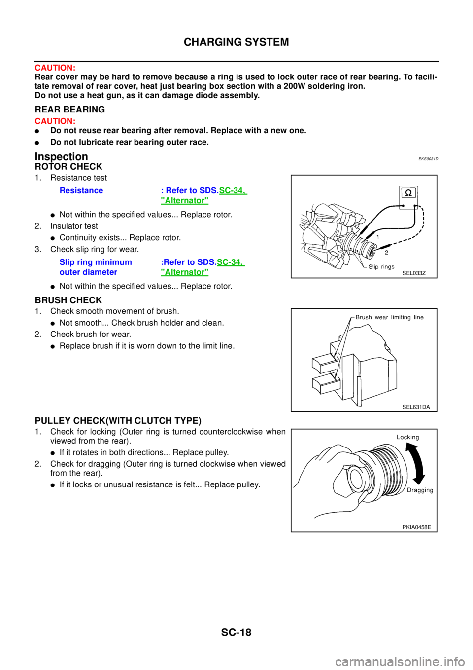
ROTOR CHECK
1. Resistance test
lNot within the specified values... Replace rotor.
2. Insulator test
lContinuity exists... Replace rotor.
3. Check slip ring for wear.
lNot within the specified values... Replace rotor.
BRUSH CHECK
1. Check smooth movement of brush.
lNot smooth... Check brush holder and clean.
2. Check brush for wear.
lReplace brush if it is worn down to the limit line.
PULLEY CHECK(WITH CLUTCH TYPE)
1. Check for locking (Outer ring is turned counterclockwise when
viewed from the rear).
lIf it rotates in both directions... Replace pulley.
2. Check for dragging (Outer ring is turned clockwise when viewed
from the rear).
lIf it locks or unusual resistance is felt... Replace pulley. Resistance : Refer to SDS.SC-34,
"Alternator"
Slip ring minimum
outer diameter:Refer to SDS.SC-34,
"Alternator"SEL033Z
SEL631DA
PKIA0458E
Page 2906 of 3066

SC-34
SERVICE DATA AND SPECIFICATIONS (SDS)
SERVICE DATA AND SPECIFICATIONS (SDS)
PFP:00030
BatteryEKS0031Q
StarterEKS0031R
AlternatorEKS0031S
Applied modelQR20 engine
YD22 engine
Standard Option
Type 55D23L 80D26L 110D26L
Capacity V-AH 12-48 12-55 12-70
Ty p eS114-844 M0T87081 M8T71471
HITACHI make MITSUBISHI make
Reduction
Applied model QR20 engine YD22 engine
System voltage V12
No-loadTerminal voltage V 11.0
Current A Less than 90 Less than 90 Less than 145
Revolution rpm More than 2,700 More than 2,500 More than 3,300
Minimum diameter of commutator mm (in) 28.0 (1.102) 28.8 (1.134) 31.4 (1.236)
Minimum length of brush mm (in) 10.5 (0.413) 7.0 (0.276) 11.0 (0.433)
Brush spring tension N (kg, lb) 16.2(1.65, 3.64)15.0 - 20.4(1.5 - 2.1, 3.4
-4.6)26.7 - 36.1(2.7 - 3.7, 6.0
-8.2)
Clearance between bearing metal and armature
shaft mm (in)Less than 0.2 (0.008) —
Clearance “l” between pinion front edge and pinion
stopper mm (in)0.3 - 2.5 (0.012 - 0.098) 0.5 - 2.0(0.020 - 0.079) —
Movement “l” in height of pinion assembly mm (in) — 0.5 - 2.0(0.020 - 0.079)
Ty p eLR1110-713 A3TB0771
HITACHI make MITSUBISHI make
Applied model QR20 engine YD22 engine
Nominal rating V-A 12-110 12-90
Ground polarityNegative
Minimum revolutions under no-load (When 13.5V is
applied) rpmLess than 1,100 Less than 1,300
Hot output current (When 13.5V is applied) A/rpmMore than35/1,300
More than91/2,500
More than110/5,000More than29/1,300
More than76/2,500
More than88/5,000
Regulated output voltage V 14.1 - 14.7
Minimum length of brush mm (in) More than 6.0 (0.236) More than 5.0 (0.197)
Brush spring pressure N (g, oz) 1.0 - 3.43 (102 - 350, 3.60 - 12.34) 4.8 - 6.0 (490 - 610, 17.28 - 21.51)
Slip ring minimum diameter mm (in) More than 26.0 (1.024) More than 22.1 (0.870)
Rotor coil resistance at 20°(68°F)W2.31 2.1 - 2.5