2003 NISSAN X-TRAIL alternator
[x] Cancel search: alternatorPage 2189 of 3066
![NISSAN X-TRAIL 2003 Electronic Repair Manual SERVICE DATA AND SPECIFICATIONS (SDS)
EM-219
[YD22DDTi]
C
D
E
F
G
H
I
J
K
L
MA
EM
MISCELLANEOUS COMPONENTS
Flywheel
Unit: mm (in)
*: Total indicator reading
Bearing Clearance
Unit: mm (in)
Tightening NISSAN X-TRAIL 2003 Electronic Repair Manual SERVICE DATA AND SPECIFICATIONS (SDS)
EM-219
[YD22DDTi]
C
D
E
F
G
H
I
J
K
L
MA
EM
MISCELLANEOUS COMPONENTS
Flywheel
Unit: mm (in)
*: Total indicator reading
Bearing Clearance
Unit: mm (in)
Tightening](/manual-img/5/57402/w960_57402-2188.png)
SERVICE DATA AND SPECIFICATIONS (SDS)
EM-219
[YD22DDTi]
C
D
E
F
G
H
I
J
K
L
MA
EM
MISCELLANEOUS COMPONENTS
Flywheel
Unit: mm (in)
*: Total indicator reading
Bearing Clearance
Unit: mm (in)
Tightening TorqueEBS00BPP
*1: Parts to be tightened in particular orders.
1)-: Order of tightening when tightening two or more times separately.
Unit: N·m (kg-m, ft-lb)
Unit: N·m (kg-m, in-lb)*2
Flywheel runout [TIR]*Standard 0.45 (0.0177) or less
Limit 1.3 (0.051) or less
Main bearing clearanceStandard 0.039 - 0.066 (0.0015 - 0.0026)
Limit 0.10 (0.0039)
Connecting rod bearing clear-
anceStandard 0.031 - 0.061 (0.0012 - 0.0024)
Limit 0.09 (0.0035)
Alternator Nut C 19 - 24 (1.9 - 2.5, 14 - 18)
Nut D 44 - 57 (4.4 - 5.9, 32 - 42)
Idler pulely Nut A 31 - 39 (3.1 - 4.0, 23 - 28 )
Catalyst44 - 53 (4.4 - 5.5 , 32 - 39)
Catalyst rear diffuser30 - 37 (3.0 - 3.8 ,22 - 27 )
Catalyst insulator
6.4 - 8.3 (0.65 - 0.85, 57 - 73)*
2
Turbocharger44.0 - 53.0 (4.4 - 5.5, 32 -39 )
Charge air cooler19.6 - 23.5( 2.0 - 2.3,15 - 17 )
Charge air cooler cover
6.37 - 7.45( 0.65 - 0.75 ,57- 65)*
2
EGR volume control valve 62.0 - 78.0 (6.3 - 8.0, 46 - 57)
EGR tube60.0 - 69.0 (6.1 - 7.1, 45 - 51)
EGR support21.0 - 26.0 (2.1 - 2.7, 16 - 19)
Exhaust manifold insulator
5.1 - 6.4 (0.52 - 0.66, 46 - 57)*
2
*1 Exhaust manifold29.0- 33.0 (2.9 - 3.4, 21 - 24)
*1 Rocker cover1)
6.8 - 8.8 (0.7 - 0.9, 61 - 75)*
2
2)
6.8 - 8.8 (0.7 - 0.9, 61 - 75) *2
Oil pan lower
6.4 - 7.5 (0.65 - 0.76, 57 - 66)*2
Oil pan drain plug29.4 - 39.2 (3.0 - 4.0, 22 - 28)
Oil strainer15.7 - 18.6 (1.6 - 1.9, 12 - 13)
*1 Oil pan upper M6 bolt
6.4 - 7.5 (0.65 - 0.76 ,57 - 66 )*
2
M8 bolt 19.6 - 23.5 (2.0 - 2.4, 15 - 17)
M10 bolt 30.4 - 36.3,(3.1 - 3.7 , 23 - 26 )
Vacuum pump32.0 - 42.0 (3.3 - 4.3, 24 - 30)
Cylinder head rear cover M6 bolt
8.4 - 11.0 (0.86 - 1.1, 75 - 97) *
2
Page 2359 of 3066
IDX-2
ALPHABETICAL INDEX
Numerics
4WD mode switch ...................................TF-53
,TF-57
4WD shift indicator lamp .........................TF-32,TF-54
4WD solenoid valve ................................TF-49,TF-51
4WD warning lamp ..........TF-32,TF-40,TF-55,TF-58
A
A/C air flow .........................................ATC-28
,MTC-5
A/C component layout .....................................ATC-20
A/C compressor clutch removal and installation ...........
ATC-129
A/C compressor precaution ...............................ATC-7
A/C compressor special service tool ................ATC-11
A/C diagnostic work flow (auto A/C) ................ATC-30
A/C HFC134a (R134a) system precaution ........ATC-4
A/C HFC134a (R134a) system service procedure .......
ATC-123
A/C HFC134a (R134a) system service tools ...ATC-12
A/C HFC134a system service equipment precaution ...
ATC-8
A/C lubricant (R134a) ......................................ATC-21
A/C operational check .........................ATC-51,MTC-7
A/C performance test diagnoses .....................ATC-83
A/C reray ..........................................................ATC-80
A/C self-diagnoses (auto A/C) .........................ATC-42
A/C service data specification ........................ATC-143
A/C system description (auto A/C) ...................ATC-24
A/C trouble diagnoses (auto A/C) .......ATC-30,MTC-3
A/C, A - Wiring diagram ...................................ATC-35
A/CCUT - Wiring diagram ................................EC-824
A/T - Wiring diagram - AT - FTS ......................AT-138
A/T - Wiring diagram - AT - MAIN ....................AT-389
A/T - Wiring diagram - AT - PNP/SW ...............AT-132
A/T - Wiring diagram - AT - VSS A/T .AT-144,AT-394
A/T fluid checking ..................................AT-13,MA-36
A/T fluid replacement .............................AT-13,MA-36
A/T fluid temperature sensor ...........................AT-141
A/T IND - Wiring diagram ....................................DI-51
A/T indicator ........................................................DI-51
A/T shift lock system ........................................AT-446
A/T shift lock system - Wiring diagram ............AT-447
A/T trouble diagnoses ..........................AT-56,AT-279
A/T Wiring diagram - AT - ENG SS ...AT-148,AT-433
A/T Wiring diagram AT - 1ST ...........................AT-154
A/T Wiring diagram AT - 2ND ..........................AT-161
A/T Wiring diagram AT - 3RD ..........................AT-168
A/T Wiring diagram AT - 4TH ..........................AT-175
A/T Wiring diagram AT - BA/FTS .......AT-218,AT-428
A/T Wiring diagram AT - LPSV ..........AT-188,AT-438
A/T Wiring diagram AT - OVRCSV ....AT-210,AT-418
A/T Wiring diagram AT - SSV/A .........AT-195,AT-408
A/T Wiring diagram AT - SSV/B .........AT-200,AT-413
A/T Wiring diagram AT - TCV ............AT-183,AT-423
A/T Wiring diagram AT - TPS ............AT-205,AT-403
A/T Wiring diagrawm AT - VSSMTR ..AT-224,AT-399
ABS - Wiring diagram .....................................BRC-12
Absolute pressure sensor ................................EC-749
Accelerator control system ...............................ACC-2
Accelerator pedal position (APP) sensor ........EC-154,
EC-484
,EC-715
Accelerator pedal released position learning ...EC-664
Accelerator pedal released position switch ......EC-783
Actuator relay .....................................................TF-51
Aiming adjustment ...............................................LT-4
Air bag ..............................................................SRS-3
Air bag disposal ..............................................SRS-40
Air bleeding (hydraulic clutch) ..............................CL-8
Air bleeding for brake system ............................BR-10
Air cleaner and air duct(QR20DE) ....................EM-15
Air cleaner and air duct(YD22DDTi) ...............EM-112
Air cleaner filter replacement(QR20DE) ...........MA-23
Air cleaner filter replacement(YD22DDTi) .........MA-31
Air cleaner filter(QR20DE) ................................EM-15
Air cleaner filter(YD22DDTi) ...........................EM-112
Air conditioner cut control .....EC-27,EC-392,EC-662
Air flow meter - See Mass air flow sensor .......EC-130,
EC-260
,EC-463
Air mix door control linkage adjustment .........ATC-64,
ATC-119
,MTC-9,MTC-28
Air mix. door motor .........................ATC-61,ATC-119
Air spoiler, rear ...................................................EI-21
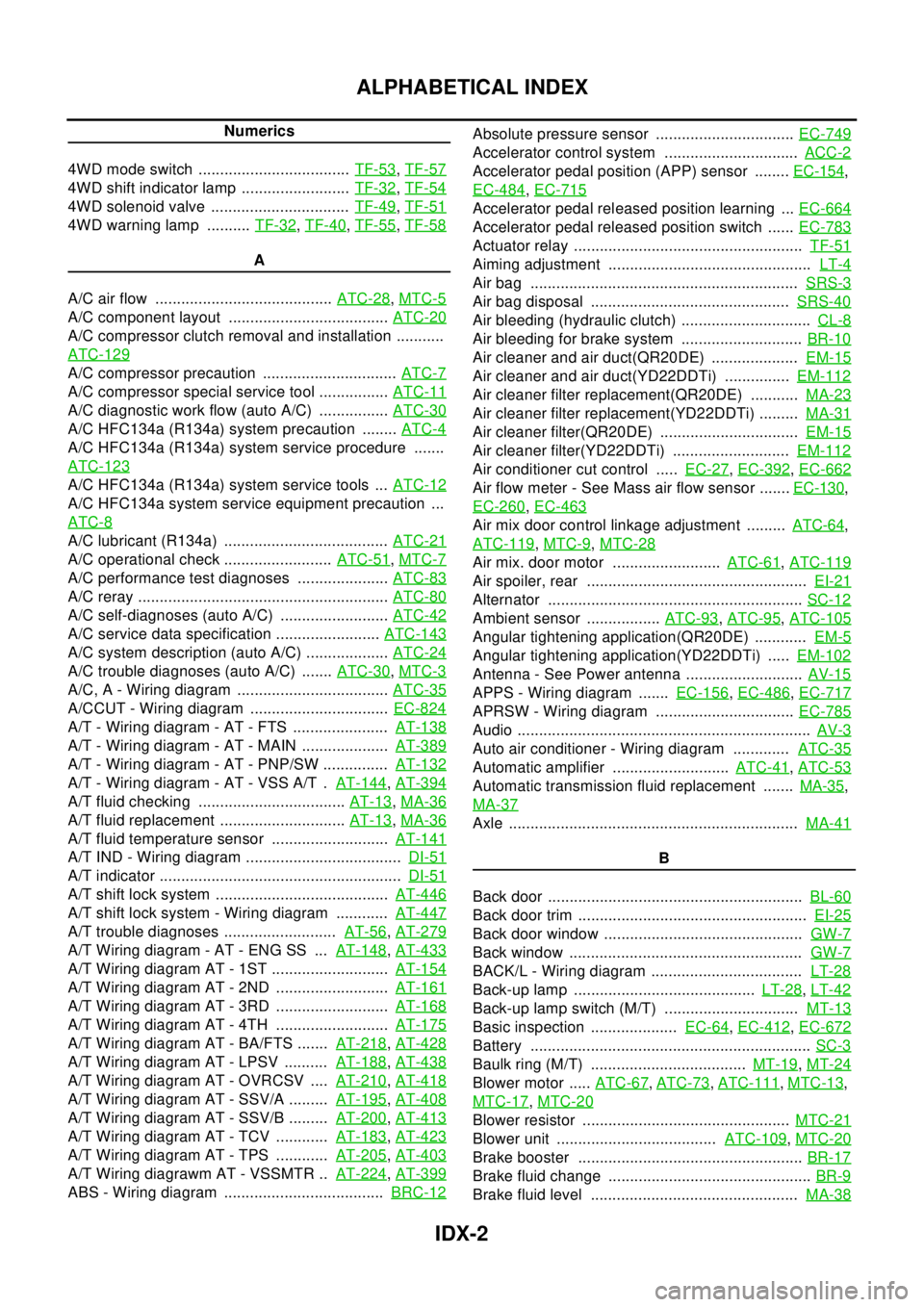
Alternator ...........................................................SC-12
Ambient sensor .................ATC-93,ATC-95,ATC-105
Angular tightening application(QR20DE) ............EM-5
Angular tightening application(YD22DDTi) .....EM-102
Antenna - See Power antenna ...........................AV-15
APPS - Wiring diagram .......EC-156,EC-486,EC-717
APRSW - Wiring diagram ................................EC-785
Audio ....................................................................AV-3
Auto air conditioner - Wiring diagram .............ATC-35
Automatic amplifier ...........................ATC-41,ATC-53
Automatic transmission fluid replacement .......MA-35,
MA-37
Axle ...................................................................MA-41
B
Back door ...........................................................BL-60
Back door trim .....................................................EI-25
Back door window ..............................................GW-7
Back window ......................................................GW-7
BACK/L - Wiring diagram ...................................LT-28
Back-up lamp ..........................................LT-28,LT-42
Back-up lamp switch (M/T) ...............................MT-13
Basic inspection ....................EC-64,EC-412,EC-672
Battery .................................................................SC-3
Baulk ring (M/T) ....................................MT-19,MT-24
Blower motor .....ATC-67,ATC-73,ATC-111,MTC-13,
MTC-17
,MTC-20
Blower resistor ................................................MTC-21
Blower unit .....................................ATC-109,MTC-20
Brake booster ....................................................BR-17
Brake fluid change ...............................................BR-9
Brake fluid level ................................................MA-38
Page 2362 of 3066
IDX-5
A
C
D
E
F
G
H
I
J
K
L B
IDX
ALPHABETICAL INDEX
Front washer ......................................................WW-4
Front wiper .........................................................WW-4
FTS - Wiring diagram ......................................EC-752
Fuel check valve ..............................................EC-372
Fuel cut control (at no load high engine speed)EC-28,
EC-393
,EC-662
Fuel filler lid ........................................................BL-64
Fuel filter ..........................................................EC-664
Fuel filter replacement(QR20DE) .........................FL-4
Fuel filter replacement(YD22DDTi) .......FL-15,MA-30
Fuel gauge ..................................................DI-4,DI-22
Fuel injection control system ...........................EC-660
Fuel injection system .........................EC-194,EC-200
Fuel injector .....................................................EC-727
Fuel injector adjustment resistor ......................EC-777
Fuel injector and fuel tube(QR20DE) ................EM-29
Fuel injector and fuel tube(YD22DDTi) ............EM-135
Fuel leak ..........................................................EC-781
Fuel line inspection(QR20DE) .................FL-3,MA-23
Fuel line inspection(YD22DDTi) ............FL-14,MA-30
Fuel pressure check ............................EC-34,EC-399
Fuel pressure release ..........................EC-34,EC-399
Fuel pressure relief valve ................................EC-665
Fuel pump ..........................................EC-352,EC-627
Fuel pump and gauge(QR20DE) ..........................FL-4
Fuel system(QR20DE) .........................................FL-3
Fuel system(YD22DDTi) .....................................FL-14
Fuel tank(QR20DE) ..............................................FL-9
Fuel tank(YD22DDTi) .........................................FL-21
Fuel temperature sensor .................................EC-751
Fuse ...................................................................PG-12
Fuse and fusible link box ...................................PG-77
Fusible link .........................................................PG-12
G
Gear components (M/T) .......................MT-19
,MT-24
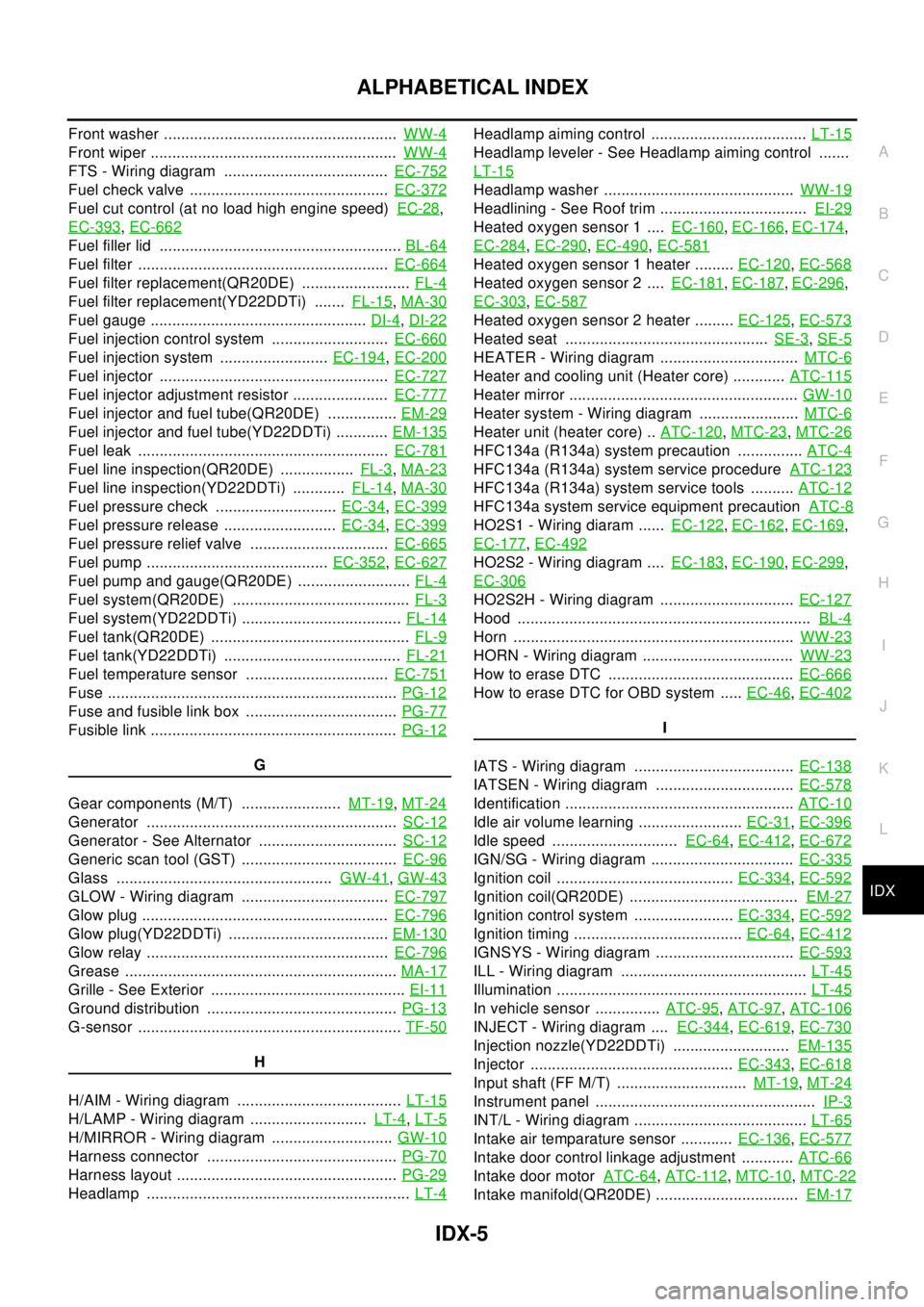
Generator ..........................................................SC-12
Generator - See Alternator ................................SC-12
Generic scan tool (GST) ....................................EC-96
Glass ..................................................GW-41,GW-43
GLOW - Wiring diagram ..................................EC-797
Glow plug .........................................................EC-796
Glow plug(YD22DDTi) .....................................EM-130
Glow relay ........................................................EC-796
Grease ...............................................................MA-17
Grille - See Exterior .............................................EI-11
Ground distribution ............................................PG-13
G-sensor .............................................................TF-50
H
H/AIM - Wiring diagram ......................................LT-15
H/LAMP - Wiring diagram ...........................LT-4,LT-5
H/MIRROR - Wiring diagram ............................GW-10
Harness connector ............................................PG-70
Harness layout ...................................................PG-29
Headlamp .............................................................LT-4
Headlamp aiming control ....................................LT-15
Headlamp leveler - See Headlamp aiming control .......
LT-15
Headlamp washer ............................................WW-19
Headlining - See Roof trim ..................................EI-29
Heated oxygen sensor 1 ....EC-160,EC-166,EC-174,
EC-284
,EC-290,EC-490,EC-581
Heated oxygen sensor 1 heater .........EC-120,EC-568
Heated oxygen sensor 2 ....EC-181,EC-187,EC-296,
EC-303
,EC-587
Heated oxygen sensor 2 heater .........EC-125,EC-573
Heated seat ...............................................SE-3,SE-5
HEATER - Wiring diagram ................................MTC-6
Heater and cooling unit (Heater core) ............ATC-115
Heater mirror .....................................................GW-10
Heater system - Wiring diagram .......................MTC-6
Heater unit (heater core) ..ATC-120,MTC-23,MTC-26
HFC134a (R134a) system precaution ...............ATC-4
HFC134a (R134a) system service procedureATC-123
HFC134a (R134a) system service tools ..........ATC-12
HFC134a system service equipment precautionATC-8
HO2S1 - Wiring diaram ......EC-122,EC-162,EC-169,
EC-177
,EC-492
HO2S2 - Wiring diagram ....EC-183,EC-190,EC-299,
EC-306
HO2S2H - Wiring diagram ...............................EC-127
Hood ....................................................................BL-4
Horn .................................................................WW-23
HORN - Wiring diagram ...................................WW-23
How to erase DTC ...........................................EC-666
HowtoeraseDTCforOBDsystem .....EC-46,EC-402
I
IATS - Wiring diagram .....................................EC-138
IATSEN - Wiring diagram ................................EC-578
Identification .....................................................ATC-10
Idle air volume learning ........................EC-31,EC-396
Idle speed .............................EC-64,EC-412,EC-672
IGN/SG - Wiring diagram .................................EC-335
Ignition coil .........................................EC-334,EC-592
Ignition coil(QR20DE) .......................................EM-27
Ignition control system .......................EC-334,EC-592
Ignition timing .......................................EC-64,EC-412
IGNSYS - Wiring diagram ................................EC-593
ILL - Wiring diagram ...........................................LT-45
Illumination ..........................................................LT-45
In vehicle sensor ...............ATC-95,ATC-97,ATC-106
INJECT - Wiring diagram ....EC-344,EC-619,EC-730
Injection nozzle(YD22DDTi) ...........................EM-135
Injector ...............................................EC-343,EC-618
Input shaft (FF M/T) ..............................MT-19,MT-24
Instrument panel ...................................................IP-3
INT/L - Wiring diagram ........................................LT-65
Intake air temparature sensor ............EC-136,EC-577
Intake door control linkage adjustment ............ATC-66
Intake door motorATC-64,ATC-112,MTC-10,MTC-22
Intake manifold(QR20DE) .................................EM-17
Page 2407 of 3066
HEADLAMP - DAYTIME LIGHT SYSTEM -
LT-9
C
D
E
F
G
H
I
J
L
MA
B
LT
HEADLAMP - DAYTIME LIGHT SYSTEM -PFP:26010
System DescriptionEKS003BB
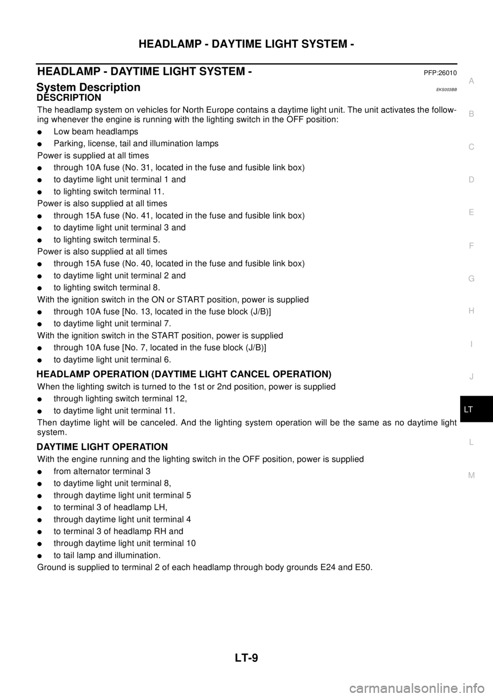
DESCRIPTION
The headlamp system on vehicles for North Europe contains a daytime light unit. The unit activates the follow-
ing whenever the engine is running with the lighting switch in the OFF position:
lLow beam headlamps
lParking, license, tail and illumination lamps
Power is supplied at all times
lthrough 10A fuse (No. 31, located in the fuse and fusible link box)
lto daytime light unit terminal 1 and
lto lighting switch terminal 11.
Power is also supplied at all times
lthrough 15A fuse (No. 41, located in the fuse and fusible link box)
lto daytime light unit terminal 3 and
lto lighting switch terminal 5.
Power is also supplied at all times
lthrough 15A fuse (No. 40, located in the fuse and fusible link box)
lto daytime light unit terminal 2 and
lto lighting switch terminal 8.
With the ignition switch in the ON or START position, power is supplied
lthrough 10A fuse [No. 13, located in the fuse block (J/B)]
lto daytime light unit terminal 7.
With the ignition switch in the START position, power is supplied
lthrough 10A fuse [No. 7, located in the fuse block (J/B)]
lto daytime light unit terminal 6.
HEADLAMP OPERATION (DAYTIME LIGHT CANCEL OPERATION)
When the lighting switch is turned to the 1st or 2nd position, power is supplied
lthrough lighting switch terminal 12,
lto daytime light unit terminal 11.
Then daytime light will be canceled. And the lighting system operation will be the same as no daytime light
system.
DAYTIME LIGHT OPERATION
With the engine running and the lighting switch in the OFF position, power is supplied
lfrom alternator terminal 3
lto daytime light unit terminal 8,
lthrough daytime light unit terminal 5
lto terminal 3 of headlamp LH,
lthrough daytime light unit terminal 4
lto terminal 3 of headlamp RH and
lthrough daytime light unit terminal 10
lto tail lamp and illumination.
Ground is supplied to terminal 2 of each headlamp through body grounds E24 and E50.
Page 2412 of 3066
LT-14
HEADLAMP - DAYTIME LIGHT SYSTEM -
Trouble Diagnoses
EKS003CO
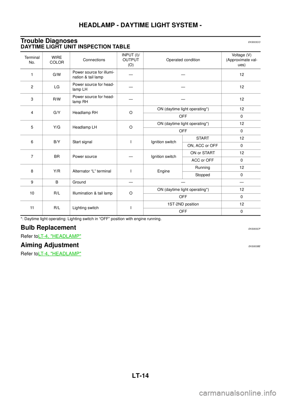
DAYTIME LIGHT UNIT INSPECTION TABLE
*: Daytime light operating: Lighting switch in “OFF” position with engine running.
Bulb ReplacementEKS003CP
Refer toLT- 4 , "HEADLAMP"
Aiming AdjustmentEKS003BE
Refer toLT- 4 , "HEADLAMP"
Te r m i n a l
No.WIRE
COLORConnectionsINPUT (I)/
OUTPUT
(O)Operated conditionVo l ta g e (V )
(Approximate val-
ues)
1G/WPower source for illumi-
nation & tail lamp—— 12
2LGPower source for head-
lamp LH—— 12
3R/WPower source for head-
lamp RH—— 12
4G/YHeadlampRH OON (daytime light operating*) 12
OFF 0
5Y/GHeadlampLH OON (daytime light operating*) 12
OFF 0
6 B/Y Start signal I Ignition switchSTART 12
ON, ACC or OFF 0
7 BR Power source — Ignition switchON or START 12
ACC or OFF 0
8 Y/R Alternator “L” terminal I EngineRunning 12
Stopped 0
9 B Ground — — —
10 R/L Illumination & tail lamp OON (daytime light operating*) 12
OFF 0
11 R/L Lighting switch I1ST·2ND position 12
OFF 0
Page 2519 of 3066
ENGINE MAINTENANCE (YD22DDTI)
MA-27
C
D
E
F
G
H
I
J
K
MA
B
MA
ENGINE MAINTENANCE (YD22DDTI)PFP:00100
Checking Drive BeltsEL S00 0C C
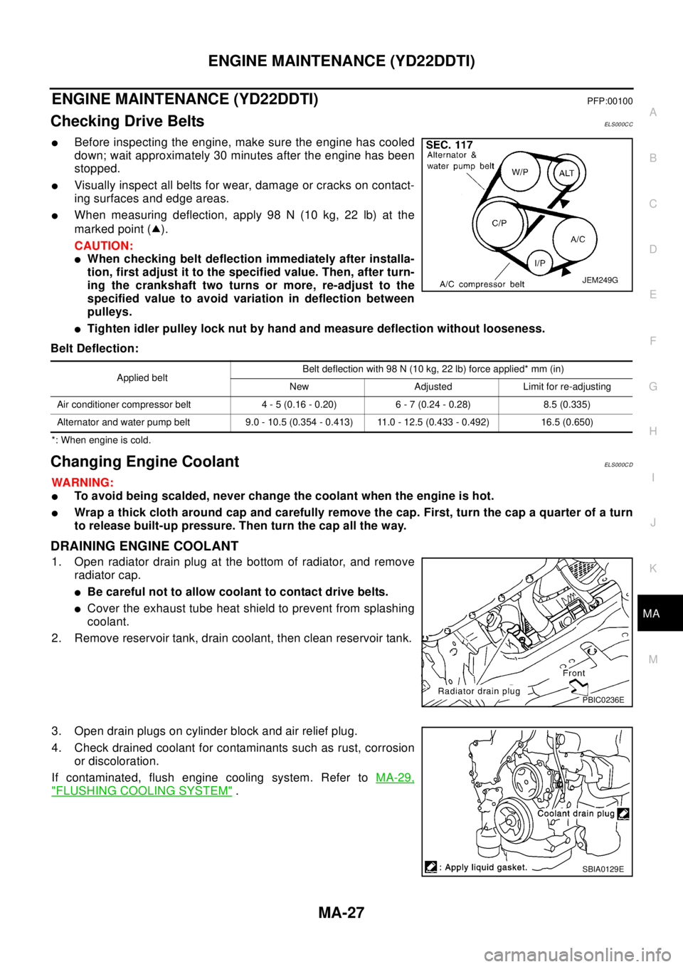
lBefore inspecting the engine, make sure the engine has cooled
down; wait approximately 30 minutes after the engine has been
stopped.
lVisually inspect all belts for wear, damage or cracks on contact-
ing surfaces and edge areas.
lWhen measuring deflection, apply 98 N (10 kg, 22 lb) at the
marked point ( ).
CAUTION:
lWhen checking belt deflection immediately after installa-
tion, first adjust it to the specified value. Then, after turn-
ing the crankshaft two turns or more, re-adjust to the
specified value to avoid variation in deflection between
pulleys.
lTighten idler pulley lock nut by hand and measure deflection without looseness.
Belt Deflection:
*: When engine is cold.
Changing Engine CoolantEL S00 0C D
WA RN ING:
lTo avoid being scalded, never change the coolant when the engine is hot.
lWrap a thick cloth around cap and carefully remove the cap. First, turn the cap a quarter of a turn
to release built-up pressure. Then turn the cap all the way.
DRAINING ENGINE COOLANT
1. Open radiator drain plug at the bottom of radiator, and remove
radiator cap.
lBe careful not to allow coolant to contact drive belts.
lCover the exhaust tube heat shield to prevent from splashing
coolant.
2. Remove reservoir tank, drain coolant, then clean reservoir tank.
3. Open drain plugs on cylinder block and air relief plug.
4. Check drained coolant for contaminants such as rust, corrosion
or discoloration.
If contaminated, flush engine cooling system. Refer toMA-29,
"FLUSHING COOLING SYSTEM".
JEM249G
Applied beltBelt deflection with 98 N (10 kg, 22 lb) force applied* mm (in)
New Adjusted Limit for re-adjusting
Air conditioner compressor belt 4 - 5 (0.16 - 0.20) 6 - 7 (0.24 - 0.28) 8.5 (0.335)
Alternator and water pump belt 9.0 - 10.5 (0.354 - 0.413) 11.0 - 12.5 (0.433 - 0.492) 16.5 (0.650)
PBIC0236E
SBIA0129E
Page 2873 of 3066
SC-1
STARTING & CHARGING SYSTEM
K ELECTRICAL
CONTENTS
C
D
E
F
G
H
I
J
L
M
SECTION
A
B
SC
STARTING & CHARGING SYSTEM
PRECAUTIONS .......................................................... 2
Precautions for Supplemental Restraint System
(SRS) “AIR BAG” and “SEAT BELT PRE-TEN-
SIONER” .................................................................. 2
Wiring Diagrams and Trouble Diagnosis .................. 2
BATTERY .................................................................... 3
How to Handle Battery ............................................. 3
METHODS OF PREVENTING OVER-DIS-
CHARGE ............................................................... 3
CHECKING ELECTROLYTE LEVEL .................... 3
SPECIFIC GRAVITY CHECK ............................... 4
Battery Test and Charging Chart .............................. 5
CHART I ................................................................ 5
CHART II ............................................................... 6
A: SLOW CHARGE ............................................... 7
B: STANDARD CHARGE ...................................... 8
C: QUICK CHARGE ............................................ 10
Removal and Installation .........................................11
CHARGING SYSTEM ............................................... 12
System Description ................................................ 12
Wiring Diagram — CHARGE — ............................. 13
Trouble Diagnoses ................................................. 14
WITH IC REGULATOR ....................................... 14
MALFUNCTION INDICATOR .............................. 14
Removal and Installation ........................................ 14
REMOVAL (QR ENGINE MODELS) ................... 14
REMOVAL (YD ENGINE MODELS) ................... 15
INSTALLATION ................................................... 15
Disassembly and Assembly ................................... 16
............................................................................ 16
............................................................................ 17
Disassembly ........................................................... 17
REAR COVER .................................................... 17REAR BEARING ................................................. 18
Inspection ............................................................... 18
ROTOR CHECK .................................................. 18
BRUSH CHECK .................................................. 18
PULLEY CHECK(WITH CLUTCH TYPE) ............ 18
STATOR CHECK ................................................. 19
Assembly ................................................................ 19
RING FITTING IN REAR BEARING .................... 19
REAR COVER INSTALLATION ........................... 19
STARTING SYSTEM ................................................. 21
System Description ................................................. 21
M/T MODELS ...................................................... 21
A/T MODELS ....................................................... 21
Wiring Diagram — START —/M/T models ............. 22
Wiring Diagram — START —/A/T models .............. 23
Trouble Diagnoses ................................................. 24
Removal and Installation ........................................ 25
REMOVAL ........................................................... 25
INSTALLATION ................................................... 25
Disassembly and Assembly .................................... 26
Inspection ............................................................... 28
MAGNETIC SWITCH CHECK ............................. 28
PINION/CLUTCH CHECK ................................... 29
BRUSH CHECK .................................................. 29
YOKE CHECK ..................................................... 30
ARMATURE CHECK ........................................... 31
Assembly ................................................................ 32
PINION PROTRUSION LENGTH ADJUST-
MENT .................................................................. 32
SERVICE DATA AND SPECIFICATIONS (SDS) ...... 34
Battery .................................................................... 34
Starter ..................................................................... 34
Alternator ................................................................ 34
Page 2884 of 3066

SC-12
CHARGING SYSTEM
CHARGING SYSTEM
PFP:00011
System DescriptionEKS00316
The alternator provides DC voltage to operate the vehicle's electrical system and to keep the battery charged.
The voltage output is controlled by the IC regulator.
Power is supplied at all times to alternator terminal 4 (S) through:
l120A (Gasoline engine models) or 100A (Diesel engine models) fusible link (letter A, located in the fuse
and fusible link box), and
l10A fuse (No.34, located in the fuse and fusible link box).
Terminal B supplies power to charge the battery and operate the vehicle's electrical system. Output voltage is
controlled by the IC regulator at terminal 4 (S) detecting the input voltage. The charging circuit is protected by
the 120A (Gasoline engine models) or 100A (Diesel engine models) link.
The alternator is grounded to the engine block.
With the ignition switch in the ON or START position, power is supplied
l10A fuse [No. 11, located in the fuse block (J/B)]
lto combination meter terminal 46 (LHD models) or terminal 59 (RHD models) for the charge warning
lamp.
Ground is supplied With power and ground supplied
lto terminal 64 (LHD models) or terminal 54 ( RHD models) of the combination meter
lthrough terminal 3 (L) of the alternator.
the charge warning lamp will illuminate. When the alternator is providing sufficient voltage with the engine run-
ning, the ground is opened and the charge warning lamp will go off.
If the charge warning lamp illuminates with the engine running, a fault is indicated.