2003 NISSAN X-TRAIL check engine light
[x] Cancel search: check engine lightPage 719 of 3066

REFRIGERANT LINES
ATC-141
C
D
E
F
G
H
I
K
L
MA
B
AT C
CAUTION:
Moving the electronic leak detector probe slower and closer to the suspected leak area will improve
the chances of finding a leak.
Checking System for Leaks Using the Fluorescent Leak DetectorEJS000VK
1. Check A/C system for leaks using the UV lamp and safety glasses (J-42220) in a low sunlight area (area
without windows preferable). Illuminate all components, fittings and lines. The dye will appear as a bright
green/yellow area at the point of leakage. Fluorescent dye observed at the evaporator drain opening indi-
cates an evaporator core assembly (tubes, core or TXV) leak.
2. If the suspected area is difficult to see, use an adjustable mirror or wipe the area with a clean shop rag or
cloth, with the UV lamp for dye residue.
3. After the leak is repaired, remove any residual dye using dye cleaner (J-43872) to prevent future misdiag-
nosis.
4. Perform a system performance check and verify the leak repair with an approved electronic refrigerant
leak detector.
NOTE:
Other gases in the work area or substances on the A/C components, for example, anti-freeze, windshield
washer fluid, solvents and lubricants, may falsely trigger the leak detector. Make sure the surfaces to be
checked are clean.
Clean with a dry cloth or blow off with shop air.
Do not allow the sensor tip of the detector to contact with any substance. This can also cause false readings
and may damage the detector.
Dye InjectionEJS000VL
(This procedure is only necessary when recharging the system or when the compressor has seized and was
replaced.)
1. Check A/C system static (at rest) pressure. Pressure must be at least 345 kPa (50 psi).
2. Pour one bottle (1/4 ounce / 7.4 cc) of the A/C refrigerant dye into the injector tool (J-41459).
3. Connect the injector tool to the A/C LOW PRESSURE side service fitting.
4. Start engine and switch A/C ON.
5. When the A/C operating (compressor running), inject one bottle (1/4 ounce / 7.4 cc) of fluorescent dye
through the low-pressure service valve using dye injector tool J-41459 (refer to the manufacture's operat-
ing instructions).
6. With the engine still running, disconnect the injector tool from the service fitting.
CAUTION:
Be careful the A/C system or replacing a component, pour the dye directly into the open system con-
nection and proceed with the service procedures.
7. Operate the A/C system for a minimum of 20 minutes to mix the dye with the system oil. Depending on the
leak size, operating conditions and location of the leak, it may take from minutes to days for the dye to
penetrate a leak and become visible.
Electronic Refrigerant Leak DetectorEJS000VM
PRECAUTIONS FOR HANDLING LEAK DETECTOR
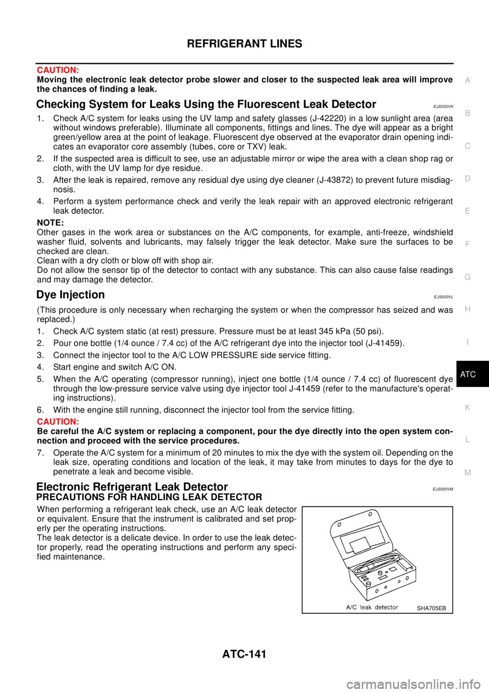
When performing a refrigerant leak check, use an A/C leak detector
or equivalent. Ensure that the instrument is calibrated and set prop-
erly per the operating instructions.
The leak detector is a delicate device. In order to use the leak detec-
tor properly, read the operating instructions and perform any speci-
fied maintenance.
SHA705EB
Page 822 of 3066

BL-78
NATS (NISSAN ANTI-THEFT SYSTEM)
Trouble Diagnoses
EIS001RX
SYMPTOM MATRIX CHART 1
Self-diagnosis related item
*: When NATS detects trouble, the security indicator lights up while ignition key is in the “ON” position.SYMPTOMDisplayed “SELF-DIAG
RESULTS ” on CON-
SULT-II screen.DIAGNOSTIC PROCE-
DURE
(Reference page)SYSTEM
(Malfunctioning part or
mode)REFERENCE PART NO.
OF ILLUSTRATION ON
SYSTEM DIAGRAM
lSecurity indicator
lighting up*
lEngine cannot be
startedECM INT CIRC-IMMUPROCEDURE 1
(BL-80
)ECM B
CHAIN OF ECM-IMMUPROCEDURE 2
(BL-80
)In rare case, “CHAIN OF
ECM-IMMU” might be
stored during key regis-
tration procedure, even if
the system is not mal-
functioning.—
Open circuit in battery
voltage line of IMMU cir-
cuitC1
Open circuit in ignition
line of IMMU circuitC2
Open circuit in ground
line of IMMU circuitC3
Open circuit in communi-
cation line between
IMMU and ECMC4
Short circuit between
IMMU and ECM commu-
nication line and battery
voltage lineC4
Short circuit between
IMMU and ECM commu-
nication line and ground
lineC4
ECM B
IMMU A
DIFFERENCE OF KEYPROCEDURE 3
(BL-82
)Unregistered key D
IMMU A
CHAIN OF IMMU-KEYPROCEDURE 4
(BL-83
)Malfunction of key ID
chipE
IMMU A
Open circuit in ground
line of dongle unit circuitC6
Open or short circuit in
line between IMMU and
dongle unitC5
Dongle unit G
ID DISCORD, IMM-ECMPROCEDURE 5
(BL-85
)System initialization has
not yet been completed.F
ECM B
LOCK MODEPROCEDURE 7
(BL-86
)LOCK MODE D
lMIL staying ON
lSecurity indicator
lighting up*DON'T ERASE
BEFORE CHECKING
ENG DIAGWORK FLOW
(BL-77)Engine trouble data and
NATS trouble data have
been detected in ECM—
Page 829 of 3066

NATS (NISSAN ANTI-THEFT SYSTEM)
BL-85
C
D
E
F
G
H
J
K
L
MA
B
BL
Diagnostic Procedure 5EIS001TB
Self-diagnostic results:
“ID DISCORD, IMM-ECM” displayed on CONSULT-II screen
1.CONFIRM SELF-DIAGNOSTIC RESULTS
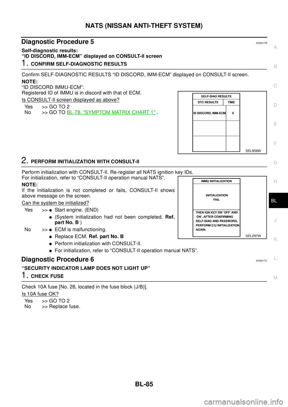
Confirm SELF-DIAGNOSTIC RESULTS “ID DISCORD, IMM-ECM” displayed on CONSULT-II screen.
NOTE:
“ID DISCORD IMMU-ECM”:
Registered ID of IMMU is in discord with that of ECM.
Is CONSULT-II screen displayed as above?
Yes >>GOTO2
No >> GO TOBL-78, "
SYMPTOM MATRIX CHART 1".
2.PERFORM INITIALIZATION WITH CONSULT-II
Perform initialization with CONSULT-II. Re-register all NATS ignition key IDs.
For initialization, refer to “CONSULT-II operation manual NATS”.
NOTE:
If the initialization is not completed or fails, CONSULT-II shows
above message on the screen.
Can the system be initialized?
Ye s > >lStart engine. (END)
l(System initialization had not been completed.Ref.
pa rt N o. B)
No >>
lECM is malfunctioning.
lReplace ECM.Ref. part No. B
lPerform initialization with CONSULT-II.
lFor initialization, refer to “CONSULT-II operation manual NATS”.
Diagnostic Procedure 6EIS001TC
“SECURITY INDICATOR LAMP DOES NOT LIGHT UP”
1.CHECK FUSE
Check 10A fuse [No. 28, located in the fuse block (J/B)].
Is 10A fuse OK?
Yes >>GOTO2
No >> Replace fuse.
SEL958W
SEL297W
Page 830 of 3066

BL-86
NATS (NISSAN ANTI-THEFT SYSTEM)
2.CHECK SECURITY INDICATOR LAMP
1. Install 10A fuse.
2. Perform initialization with CONSULT-II.
For initialization, refer to “CONSULT-II Operation Manual NATS”.
3. Turn ignition switch OFF.
4. Start engine and turn ignition switch OFF.
5. Check the security indicator lamp lighting.
Security indicator lamp should be light up.
OK or NG?
OK >> INSPECTION END
NG >> GO TO 3
3.CHECK SECURITY INDICATOR LAMP POWER SUPPLY CIRCUIT
1. Disconnect security indicator lamp connector.
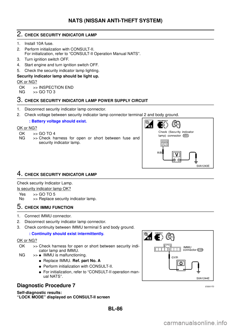
2. Check voltage between security indicator lamp connector terminal 2 and body ground.
OK or NG?
OK >> GO TO 4
NG >> Check harness for open or short between fuse and
security indicator lamp.
4.CHECK SECURITY INDICATOR LAMP
Check security Indicator Lamp.
Is security indicator lamp OK?
Yes >>GOTO5
No >> Replace security indicator lamp.
5.CHECK IMMU FUNCTION
1. Connect IMMU connector.
2. Disconnect security indicator lamp connector.
3. Check continuity between IMMU terminal 5 and body ground.
OK or NG?
OK >> Check harness for open or short between security indi-
cator lamp and IMMU.
NG >>
lIMMU is malfunctioning.
lReplace IMMU.Ref. part No. A
lPerform initialization with CONSULT-II.
lFor initialization, refer to “CONSULT-II operation man-
ual NATS”.
Diagnostic Procedure 7EIS001TD
Self-diagnostic results:
“LOCK MODE” displayed on CONSULT-II screen: Battery voltage should exist.
SIIA1243E
: Continuity should exist intermittently.
SIIA1244E
Page 874 of 3066
![NISSAN X-TRAIL 2003 Electronic Repair Manual BRC-6
[4WD/ABS]
ALL MODE 4X4 SYSTEM
ALL MODE 4X4 SYSTEM
PFP:47850
System DescriptionEFS001CJ
ABS FUNCTION
lDuring ABS operation, brake pedal lightly vibrates and its mechanical noise may be heard. Thi NISSAN X-TRAIL 2003 Electronic Repair Manual BRC-6
[4WD/ABS]
ALL MODE 4X4 SYSTEM
ALL MODE 4X4 SYSTEM
PFP:47850
System DescriptionEFS001CJ
ABS FUNCTION
lDuring ABS operation, brake pedal lightly vibrates and its mechanical noise may be heard. Thi](/manual-img/5/57402/w960_57402-873.png)
BRC-6
[4WD/ABS]
ALL MODE 4X4 SYSTEM
ALL MODE 4X4 SYSTEM
PFP:47850
System DescriptionEFS001CJ
ABS FUNCTION
lDuring ABS operation, brake pedal lightly vibrates and its mechanical noise may be heard. This is a nor-
mal condition.
lWhen starting engine, or just after starting vehicle, brake pedal may vibrate. Also motor operating noise
may be heard from engine compartment. This is a normal status of operation check.
lWhen vehicle drives on rough, gravel, or snowy (fresh deep snow) road, the following conditions occur.
Stopping distance may be longer than that of vehicles without ABS.
4WD FUNCTION
lElectronically controlled 4WD is controlled by the same control module as that for ABS (4WD/ABS control
unit). 4WD/ABS control unit controls both electronically-controlled 4WD and ABS, based on input signals
from several sensors.
lIf electrical system-related malfunction occurred in 4WD/ABS system, control unit illuminates the following
lamps: 4WD warning lamp and/or ABS warning lamp on meter control unit assembly. This notifies driver of
malfunction. At the same time, control unit indicates malfunctioning part detected by self-diagnosis with
flashing pattern of LED. Indication on electronic system diagnosis tester (CONSULT) corresponds to this
flashing pattern as shown below.
Control System DiagramEFS001CK
Self-diagnostic test mode Remarks
Result of self-diagnosis Conformable to 4WD/ABS
Data monitor Conformable to 4WD/ABS
Active testChecks ABS solenoid valve ON/OFF, ABS motor ON/OFF, 4WD sole-
noid
Control unit part No. 4WD/ABS control unit
SFIA0350E
Page 887 of 3066
![NISSAN X-TRAIL 2003 Electronic Repair Manual TROUBLE DIAGNOSIS
BRC-19
[4WD/ABS]
C
D
E
G
H
I
J
K
L
MA
B
BRC
CAUTION:
1. Light tight-corner braking symptom may occur depending on driving conditions in AUTO mode.
This is not malfunction.
2. Heavy t NISSAN X-TRAIL 2003 Electronic Repair Manual TROUBLE DIAGNOSIS
BRC-19
[4WD/ABS]
C
D
E
G
H
I
J
K
L
MA
B
BRC
CAUTION:
1. Light tight-corner braking symptom may occur depending on driving conditions in AUTO mode.
This is not malfunction.
2. Heavy t](/manual-img/5/57402/w960_57402-886.png)
TROUBLE DIAGNOSIS
BRC-19
[4WD/ABS]
C
D
E
G
H
I
J
K
L
MA
B
BRC
CAUTION:
1. Light tight-corner braking symptom may occur depending on driving conditions in AUTO mode.
This is not malfunction.
2. Heavy tight-corner braking symptom occurs when vehicle is driven in the following conditions:
LOCK mode, steering wheel is turned fully to either sides, and accelerator pedal was depressed.
4WD/ABS Control Unit Input/Output Signal StandardEFS001BG
4WD/ABS CONTROL UINT CONNECTOR TERMINAL ARRANGEMENT
CAUTION:
When ignition switch is turned to ON with connectors of 4WD/ABS control unit and actuator con-
nected.
REFERENCE STANDARD TABLE
Specifications defined by circuit tester
Vehicle running, 4WD warning lamp
flashes slowly. (When it flashes for
Approx. One minute, then does not illu-
minate.)Slow flashing: One flashing
per 2 secondslEngine run-
ning
lDriving at
vehicle speed
30km/hTire size is different for front and rear of vehicle.BRC-45
Vehicle does not enter 4WD mode
even though 4WD warning lamp is off.Engine runningMechanical malfunction of electronically con-
trolled coupling (Mechanical engagement of
clutch is not possible.)BRC-46
Symptom Condition Check items Reference page
SFIA0351E
Terminal No.
Location Standard (note 1)(Note) Check
points when result
was malfunctioning +-
3.
109Power supply Ignition switch ONBattery voltage (Approx.
12V)Control unit power
supply circuit
Page 898 of 3066
![NISSAN X-TRAIL 2003 Electronic Repair Manual BRC-30
[4WD/ABS]
TROUBLE DIAGNOSIS
NOTE:
lIf active test is performed with brake pedal depressed, pedal
stroke may be changed. This is a normal condition.
l“TEST STOP” is displayed 10 seconds late NISSAN X-TRAIL 2003 Electronic Repair Manual BRC-30
[4WD/ABS]
TROUBLE DIAGNOSIS
NOTE:
lIf active test is performed with brake pedal depressed, pedal
stroke may be changed. This is a normal condition.
l“TEST STOP” is displayed 10 seconds late](/manual-img/5/57402/w960_57402-897.png)
BRC-30
[4WD/ABS]
TROUBLE DIAGNOSIS
NOTE:
lIf active test is performed with brake pedal depressed, pedal
stroke may be changed. This is a normal condition.
l“TEST STOP” is displayed 10 seconds later from the operation
start.
lTo perform test again after “TEST STOP” is displayed, repeat
step 6 of operation procedure.
ABS motor
Touch “ON” and “OFF” on screen. Check ABS motor relay operates
as shown in the following chart.
NOTE:
lIf active test is performed with brake pedal depressed, pedal
stroke may be changed. This is a normal condition.
l“TEST STOP” is displayed 10 seconds later from the operation
start.
Active test
4WD solenoid valve
Under the vehicle stopped with engine running, touch UP, DOWN on
screen. Adjust 4WD solenoid command current.
Check the monitor current at that time. If monitor current is within
Approx.±10%, light switch is normal.
CAUTION:
Do not continuously energize solenoid for long period of time.
Component InspectionEFS001BJ
ABS ACTUATOR
lDisconnect each ABS actuator E69, E70, E71 connector. Con-
firm continuity and resistance value between each pair of ABS
actuator-side terminal.
CAUTION:
Be sure ABS motor is securely grounded.
SFIA0396E
Operation ON OFF
ABS actuator ON ON
ABS motor ON OFF
SFIA0397E
SDIA0626E
SFIA0352E
Page 913 of 3066
![NISSAN X-TRAIL 2003 Electronic Repair Manual TROUBLE DIAGNOSIS
BRC-45
[4WD/ABS]
C
D
E
G
H
I
J
K
L
MA
B
BRC
3.INSPECTION USING DRIVE MODE CHANGE-OVER SWITCH
lOn data monitor screen of the CONSULT, check 4WD mode switch.
lCheck if the display chan NISSAN X-TRAIL 2003 Electronic Repair Manual TROUBLE DIAGNOSIS
BRC-45
[4WD/ABS]
C
D
E
G
H
I
J
K
L
MA
B
BRC
3.INSPECTION USING DRIVE MODE CHANGE-OVER SWITCH
lOn data monitor screen of the CONSULT, check 4WD mode switch.
lCheck if the display chan](/manual-img/5/57402/w960_57402-912.png)
TROUBLE DIAGNOSIS
BRC-45
[4WD/ABS]
C
D
E
G
H
I
J
K
L
MA
B
BRC
3.INSPECTION USING DRIVE MODE CHANGE-OVER SWITCH
lOn data monitor screen of the CONSULT, check 4WD mode switch.
lCheck if the display changes from ## to 2WD mode when the 2WD switch is pressed.
lCheck if the display changes from ## to AUTO mode when the AUTO switch is pressed.
lCheck if the display changes from ## to LOCK mode when the LOCK switch is pressed.
Is inspection result OK?
YES >> No malfunction detected.
NO >>
lNot in AUTO mode. (In 2WD or LOCK mode)
Countermeasure: Slightly depress the accelerator pedal and check that the operation mode
changes to LOCK mode.
lCheck path between drive mode switch and 4WD/ABS control unit E122 terminal No.27 (BR).
(AUTO mode is not available because a malfunction is present in the 2WD mode harness.)
NOTICE:
Mechanism of drive mode change-over
l2WD mode: Operation changes to 2WD mode when 4WD/ABS control unit connector terminal
No. 27 is shorted to ground.
lAUTO mode: Operation changes to AUTO mode when 4WD/ABS control unit connector termi-
nals No. 27 and No. 26 were shorted to ground.
lLOCK mode: Operation changes to LOCK mode when 4WD/ABS control unit connector E122
terminal No. 26 (L) is shorted to ground.
Drive modes cannot be switched after engine is started.EFS001BU
1.INSPECTION USING DRIVE MODE CHANGE-OVER SWITCH
lDrive modes cannot be switched after the engine is started.
lOn data monitor screen of the CONSULT, check 4WD mode switch.
lCheck if the display changes from ## to 2WD mode when the 2WD switch is pressed.
lCheck if the display changes from ## to AUTO mode when the AUTO switch is pressed.
lCheck if the display changes from ## to LOCK mode when the LOCK switch is pressed.
Is inspection result OK?
YES >> No malfunction detected.
NO >>
lCONSULT-II display does not change from ## when the 2WD switch is pressed. Check harness
of the 2WD switch.
lCONSULT-II display does not change from ## when the AUTO switch is pressed. Check har-
ness of the 2WD switch and LOCK switch.
lCONSULT-II display does not change from ## when the LOCK switch is pressed. Check har-
ness of the LOCK switch.
lPerform drive mode change-over switch inspection.
Wheel driving, 4WD warning lamp flashes rapidly. (When it flashes for Approx.
one minute, then does not illuminate.)
EFS001BV
lWheel driving, 4WD warning lamp flashes rapidly. (When it flashes for Approx. 1 minute, then does not
illuminate.)
Rapid flashing: 2 times/second
This phenomenon protects drivetrain parts when a heavy load is applied to the electronically controlled
coupling and multiple disc clutch temperature increases. It is not a malfunction.
Wheel driving, 4WD warning lamp flashes slowly. (When it continues to illumi-
nate until engine turns OFF.)
EFS001BW
1. Check using the data monitor function of the CONSULT.
lPerform inspection with the data monitor function of the CONSULT.
lCheck if the value of IMPROPER SIZE TIRE MONITOR is 8 mm or more.