2003 NISSAN X-TRAIL FL fuel system
[x] Cancel search: FL fuel systemPage 2506 of 3066
MA-14
PERIODIC MAINTENANCE
NOTE:
lMaintenance items with “ ” should be performed more frequently according to “Maintenance Under Severe Driving
Conditions”.
l(1) If valve noise increases, check valve clearance.
l(2) Never use CG-4 oil.
l(3) Oil filter element assembly and O-ring seal are replacement parts.
l(4) First replace at 100,000 Km (60,000 miles), then every 60,000Km (36,000 miles). After first replacement, perform "I"
(checking the mixture ratio and correcting the mixture ratio if necessary) at the middle of replacement interval.
l(5) If engine power decreases, black exhaust smoke is emitted or engine noise increases, perform this maintenance item.
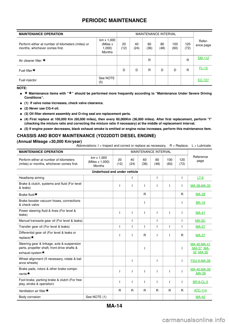
CHASSIS AND BODY MAINTENANCE (YD22DDTI DIESEL ENGINE)
(Annual Mileage >30,000 Km/year)
Abbreviations: I = Inspect and correct or replace as necessary, R = Replace, L = Lubricate. Air cleaner filterRREM-112
Fuel filterDDRDDRFL-15
Fuel injectorSee NOTE
(5)EC-727
MAINTENANCE OPERATIONMAINTENANCE INTERVAL
Refer-
ence page Perform either at number of kilometers (miles) or
months, whichever comes first.km x 1,000
(Miles x
1,000)
Months20
(12)40
(24)60
(36)80
(48)100
(60)120
(72)
MAINTENANCE OPERATIONMAINTENANCE INTERVAL
Reference
page Perform either at number of kilometers
(miles) or months, whichever comes first.km x 1,000
(Miles x 1,000)
Months20
(12)40
(24)60
(36)80
(48)100
(60)120
(72)
Underhood and under vehicle
Headlamp aiming I I ILT- 6
Brake & clutch, systems and fluid (For level
&leaks)IIIIIIMA-38,MA-35
Brake fluidRRMA-39
Brake booster vacuum hoses, connections
& check valveIIBR-19
Power steering fluid & lines (For level &
leaks)IIIIIIMA-41
Manual transaxle gear oil (For level & leaks) I I IMA-35,
Transfergearoil(Forlevel&leaks) IIIIIIMA-37
Differential gear oil (For level & leaks or
replace)IIRIIRMA-37
Steering gear & linkage, axle & suspension
parts, propeller shaft, front drive shafts &
exhaust systemIIMA-40,MA-41
,MA-37,MA-
42,MA-35
Wheel alignment (If necessary, rotate & bal-
ance wheels)IIIFSU-6,MA-38
Brake pads, rotors & other brake compo-
nentsIIIIIIMA-40,MA-39
,MA-39
Foot brake, parking brake & clutch (For free
play, stroke & operation)IIIIIIBR-6,CL-5
Ventilation air filterRRRRRRAT C -11 4
Body corrosion See NOTE (1)MA-42
Page 2507 of 3066
PERIODIC MAINTENANCE
MA-15
C
D
E
F
G
H
I
J
K
MA
B
MA
NOTE:
l(1) Inspect once per year.
lMaintenance items with “ ” should be performed more frequently according to “Maintenance Under Severe Driving
Conditions”.
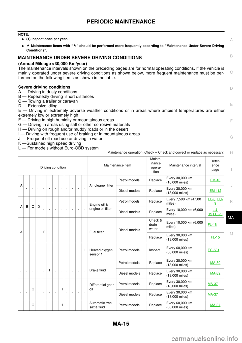
MAINTENANCE UNDER SEVERE DRIVING CONDITIONS
(Annual Mileage >30,000 Km/year)
The maintenance intervals shown on the preceding pages are for normal operating conditions. If the vehicle is
mainly operated under severe driving conditions as shown below, more frequent maintenance must be per-
formed on the following items as shown in the table.
Severe driving conditions
A — Driving in dusty conditions
B — Repeatedly driving short distances
C — Towing a trailer or caravan
D — Extensive idling
E — Driving in extremely adverse weather conditions or in areas where ambient temperatures are either
extremely low or extremely high
F — Driving in high humidity or mountainous areas
G — Driving in areas using salt or other corrosive materials
H — Driving on rough and/or muddy roads or in the desert
I — Driving with frequent use of braking or in mountainous areas
J — Frequent off road use or driving in water
K —Sustained high speed driving
L — For models without Euro-OBD system
Maintenance operation: Check = Check and correct or replace as necessary.
Driving conditionMaintenance itemMainte-
nance
opera-
tionMaintenance intervalRefer-
ence
page
A
...........Air cleaner filterPetrol models ReplaceEvery 30,000 km
(18,000 miles)EM-16
Diesel models ReplaceEvery 30,000 km
(18,000 miles)EM-112
ABCD
........Engine oil &
engine oil filterPetrol models ReplaceEvery 7,500 km (4,500
miles)LU-8
,LU-
9
Diesel models ReplaceEvery 10,000 km (6,000
miles)LU-19,LU-20
A...E.......FuelfilterDiesel modelsCheck &
drain
waterEvery 10,000 km (6,000
miles)FL-16
ReplaceEvery 30,000 km
(18,000 miles)FL-15
...........LHeatedoxygen
sensor 1Petrol models InspectEvery 60,000 km
(36,000 miles)EC-581
.....F......BrakefluidPetrol models ReplaceEvery 30,000 km
(18,000 miles)MA-39Diesel models ReplaceEvery 30,000 km
(18,000 miles)MA-39
..C
....H
....Differential gear
oilPetrol models ReplaceEvery 30,000 km
(18,000 miles)MA-37Diesel models ReplaceEvery 30,000 km
(18,000 miles)MA-37
..C....H....Automatic tran-
saxle fluidPetrol models ReplaceEvery 60,000 km
(36,000 miles)MA-37
Page 2515 of 3066
ENGINE MAINTENANCE (QR20DE)
MA-23
C
D
E
F
G
H
I
J
K
MA
B
MA
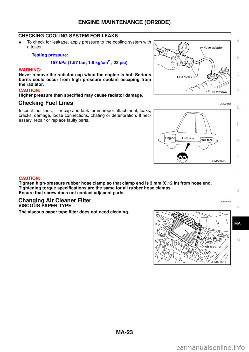
CHECKING COOLING SYSTEM FOR LEAKS
lTo check for leakage, apply pressure to the cooling system with
atester.
WA RN ING:
Never remove the radiator cap when the engine is hot. Serious
burns could occur from high pressure coolant escaping from
the radiator.
CAUTION:
Higher pressure than specified may cause radiator damage.
Checking Fuel LinesELS000AQ
Inspect fuel lines, filler cap and tank for improper attachment, leaks,
cracks, damage, loose connections, chafing or deterioration. If nec-
essary, repair or replace faulty parts.
CAUTION:
Tighten high-pressure rubber hose clamp so that clamp end is 3 mm (0.12 in) from hose end.
Tightening torque specifications are the same for all rubber hose clamps.
Ensure that screw does not contact adjacent parts.
Changing Air Cleaner FilterELS000AR
VISCOUS PAPER TYPE
The viscous paper type filter does not need cleaning.Testing pressure:
157 kPa (1.57 bar, 1.6 kg/cm
2,23psi)
SLC756AA
SMA803A
SMA037D
Page 2518 of 3066
MA-26
ENGINE MAINTENANCE (QR20DE)
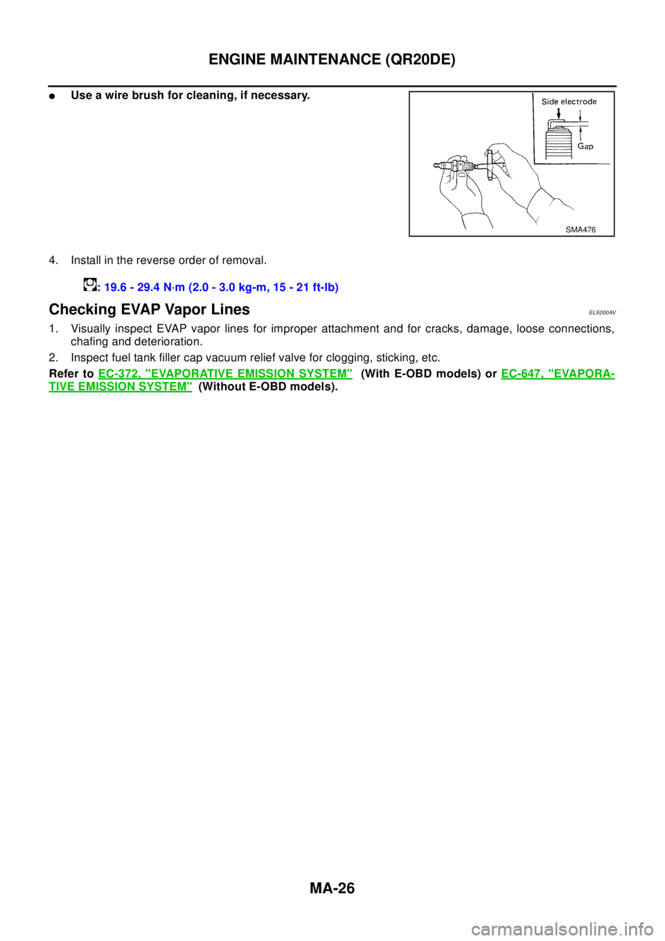
lUse a wire brush for cleaning, if necessary.
4. Install in the reverse order of removal.
Checking EVAP Vapor LinesELS000AV
1. Visually inspect EVAP vapor lines for improper attachment and for cracks, damage, loose connections,
chafing and deterioration.
2. Inspect fuel tank filler cap vacuum relief valve for clogging, sticking, etc.
Refer toEC-372, "
EVAPORATIVE EMISSION SYSTEM"(With E-OBD models) orEC-647, "EVAPORA-
TIVE EMISSION SYSTEM"(Without E-OBD models).
SMA476
: 19.6 - 29.4 N·m (2.0 - 3.0 kg-m, 15 - 21 ft-lb)
Page 2522 of 3066
MA-30
ENGINE MAINTENANCE (YD22DDTI)
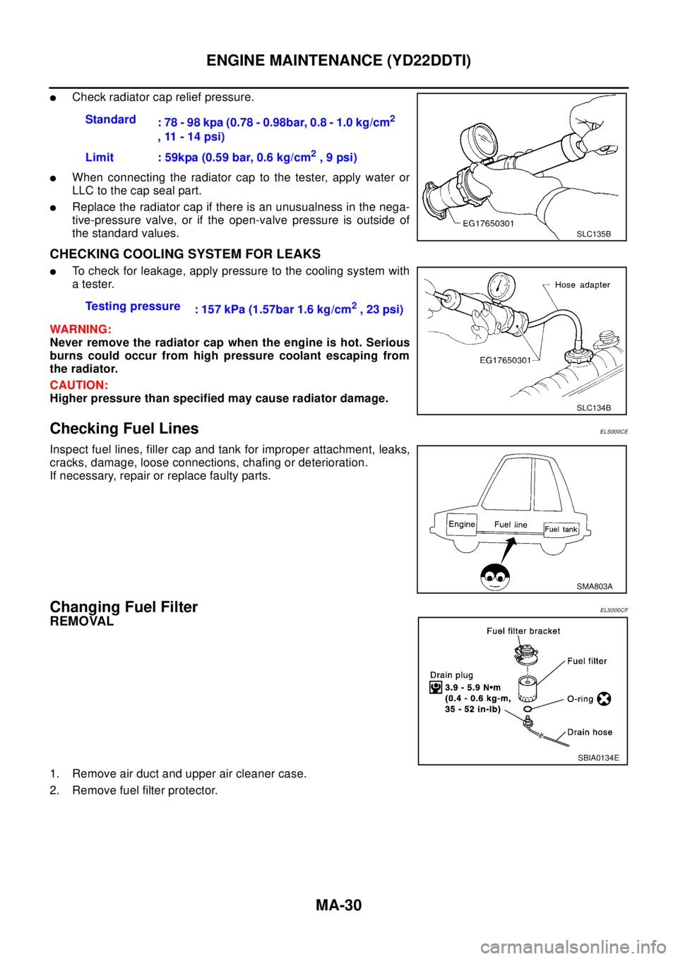
lCheck radiator cap relief pressure.
lWhen connecting the radiator cap to the tester, apply water or
LLC to the cap seal part.
lReplace the radiator cap if there is an unusualness in the nega-
tive-pressure valve, or if the open-valve pressure is outside of
the standard values.
CHECKING COOLING SYSTEM FOR LEAKS
lTo check for leakage, apply pressure to the cooling system with
atester.
WAR NIN G:
Never remove the radiator cap when the engine is hot. Serious
burns could occur from high pressure coolant escaping from
the radiator.
CAUTION:
Higher pressure than specified may cause radiator damage.
Checking Fuel LinesELS000CE
Inspect fuel lines, filler cap and tank for improper attachment, leaks,
cracks, damage, loose connections, chafing or deterioration.
If necessary, repair or replace faulty parts.
Changing Fuel FilterELS000CF
REMOVAL
1. Remove air duct and upper air cleaner case.
2. Remove fuel filter protector.Standard
: 78 - 98 kpa (0.78 - 0.98bar, 0.8 - 1.0 kg/cm
2
,11-14psi)
Limit : 59kpa (0.59 bar, 0.6 kg/cm
2,9psi)
SLC135B
Testing pressure
: 157 kPa (1.57bar 1.6 kg/cm2,23psi)
SLC134B
SMA803A
SBIA0134E
Page 2737 of 3066
HARNESS
PG-61
C
D
E
F
G
H
I
J
L
MA
B
PG
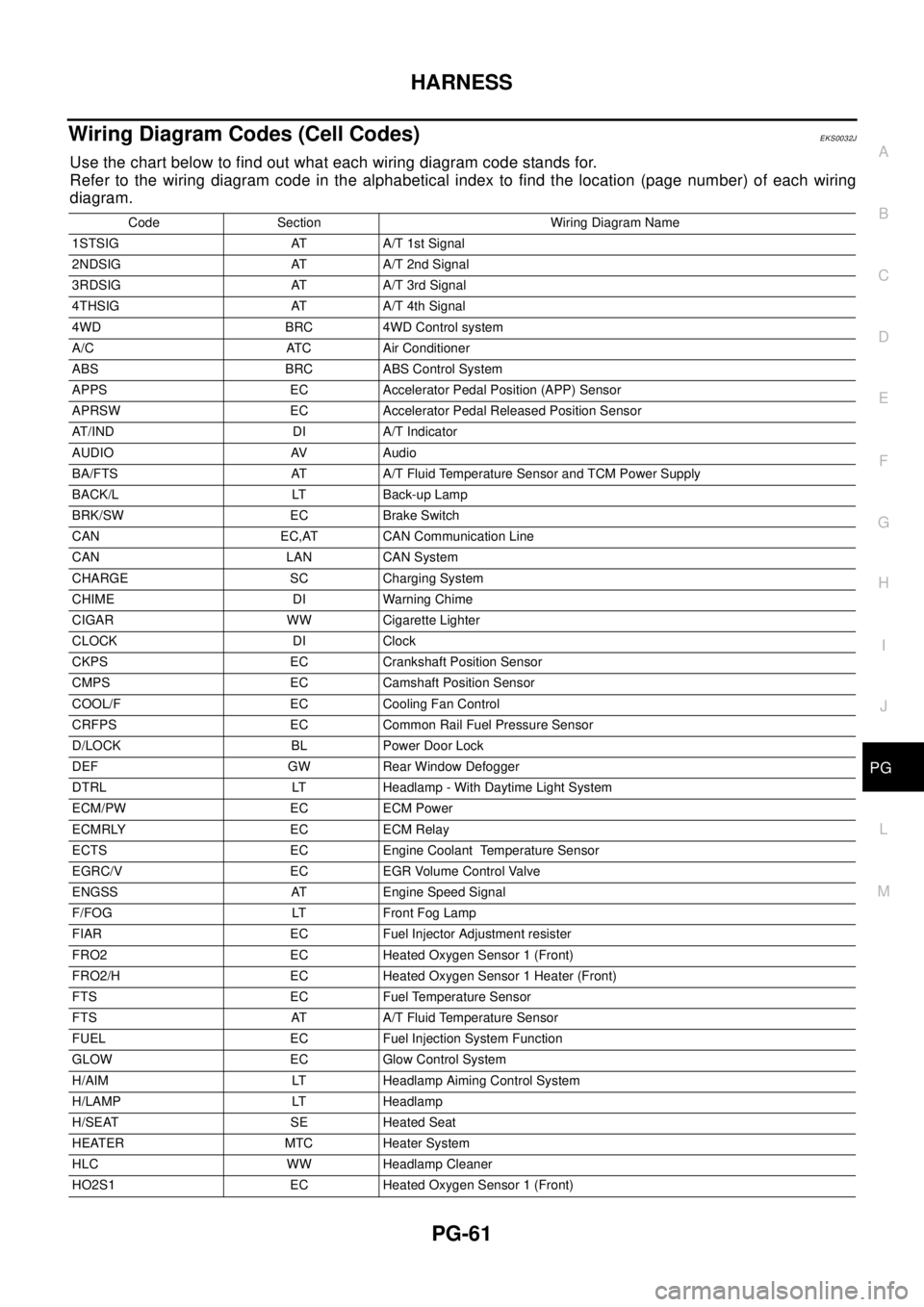
Wiring Diagram Codes (Cell Codes)EKS0032J
Use the chart below to find out what each wiring diagram code stands for.
Refer to the wiring diagram code in the alphabetical index to find the location (page number) of each wiring
diagram.
Code Section Wiring Diagram Name
1STSIG AT A/T 1st Signal
2NDSIG AT A/T 2nd Signal
3RDSIG AT A/T 3rd Signal
4THSIG AT A/T 4th Signal
4WD BRC 4WD Control system
A/C ATC Air Conditioner
ABS BRC ABS Control System
APPS EC Accelerator Pedal Position (APP) Sensor
APRSW EC Accelerator Pedal Released Position Sensor
AT/IND DI A/T Indicator
AUDIO AV Audio
BA/FTS AT A/T Fluid Temperature Sensor and TCM Power Supply
BACK/L LT Back-up Lamp
BRK/SW EC Brake Switch
CAN EC,AT CAN Communication Line
CAN LAN CAN System
CHARGE SC Charging System
CHIME DI Warning Chime
CIGAR WW Cigarette Lighter
CLOCK DI Clock
CKPS EC Crankshaft Position Sensor
CMPS EC Camshaft Position Sensor
COOL/F EC Cooling Fan Control
CRFPS EC Common Rail Fuel Pressure Sensor
D/LOCK BL Power Door Lock
DEF GW Rear Window Defogger
DTRL LT Headlamp - With Daytime Light System
ECM/PW EC ECM Power
ECMRLY EC ECM Relay
ECTS EC Engine Coolant Temperature Sensor
EGRC/V EC EGR Volume Control Valve
ENGSS AT Engine Speed Signal
F/FOG LT Front Fog Lamp
FIAR EC Fuel Injector Adjustment resister
FRO2 EC Heated Oxygen Sensor 1 (Front)
FRO2/H EC Heated Oxygen Sensor 1 Heater (Front)
FTS EC Fuel Temperature Sensor
FTS AT A/T Fluid Temperature Sensor
FUEL EC Fuel Injection System Function
GLOW EC Glow Control System
H/AIM LT Headlamp Aiming Control System
H/LAMP LT Headlamp
H/SEAT SE Heated Seat
HEATER MTC Heater System
HLC WW Headlamp Cleaner
HO2S1 EC Heated Oxygen Sensor 1 (Front)
Page 2798 of 3066
RAX-2
PRECAUTIONS
PRECAUTIONS
PFP:00001
CautionEDS00060
Observe the following precautions when disassembling and servicing drive shaft.
lPerform work in a location which is as dust-free and dirt-free as possible.
lBefore disassembling and servicing, clean the outside of parts.
lThe disassembly and service location must be clean. Care must be taken to prevent parts from becoming
dirty and to prevent the entry of foreign objects.
lDisassembled parts must be carefully reassembled in the correct order. If work is interrupted, a clean
cover must be placed over parts.
lPaper shop cloths must be used. Fabric shop cloths must not be used because of the danger of lint adher-
ing to parts.
lDisassembled parts (except for rubber parts) should be cleaned with kerosene which shall be removed by
blowing with air or wiping with paper shop cloths.
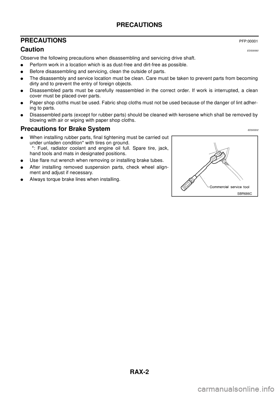
Precautions for Brake SystemEDS0 00 I2
lWhen installing rubber parts, final tightening must be carried out
under unladen condition* with tires on ground.
*: Fuel, radiator coolant and engine oil full. Spare tire, jack,
hand tools and mats in designated positions.
lUse flare nut wrench when removing or installing brake tubes.
lAfter installing removed suspension parts, check wheel align-
ment and adjust if necessary.
lAlways torque brake lines when installing.
SBR686C
Page 2824 of 3066
RFD-2
PRECAUTIONS
PRECAUTIONS
PFP:00001
CautionEDS00056
lBefore starting diagnosis of the vehicle, understand symptoms well. Perform correct and systematic oper-
ations.
lCheck for the correct installation status prior to removal or disassembly. When mating marks are required,
be sure they do not interfere with the function of the parts they are applied to.
lCarry out an overhaul in a clean work place. Using a dust proof room is recommended.
lBefore disassembly, using steam or white gasoline, completely remove sand and mud from the exterior of
the unit, preventing them from entering into the unit during disassembly or assembly.
lCheck appearance of the disassembled parts for damage, deformation, and abnormal wear. If a malfunc-
tion is detected, replace it with a new one.
lNormally replace lock pins, oil seals, and bearings with new ones every time they are removed.
lIn principle, tighten bolts or nuts gradually in several steps working diagonally from inside to outside. If
tightening sequence is specified, observe it.
lClean and flush the parts sufficiently and blow them dry.
lBe careful not to damage the sliding surfaces and mating surfaces.
lWhen applying sealant, remove the old sealant from the mounting surface; then remove any moisture, oil,
and foreign materials from the application and mounting surfaces.
lAlways use shop paper for cleaning the inside of components.
lAvoid using cotton gloves or a shop cloth to prevent entering of lint.
lDuring assembly, observe the specified tightening torque, and apply new differential oil, Vaseline, or Nis-
san MP Special Grease No. 2, as specified for each vehicle, when necessary.
lDo not reuse drained oil. Discard waste oil after oil changes or part treatment in accordance with local
laws and regulations.
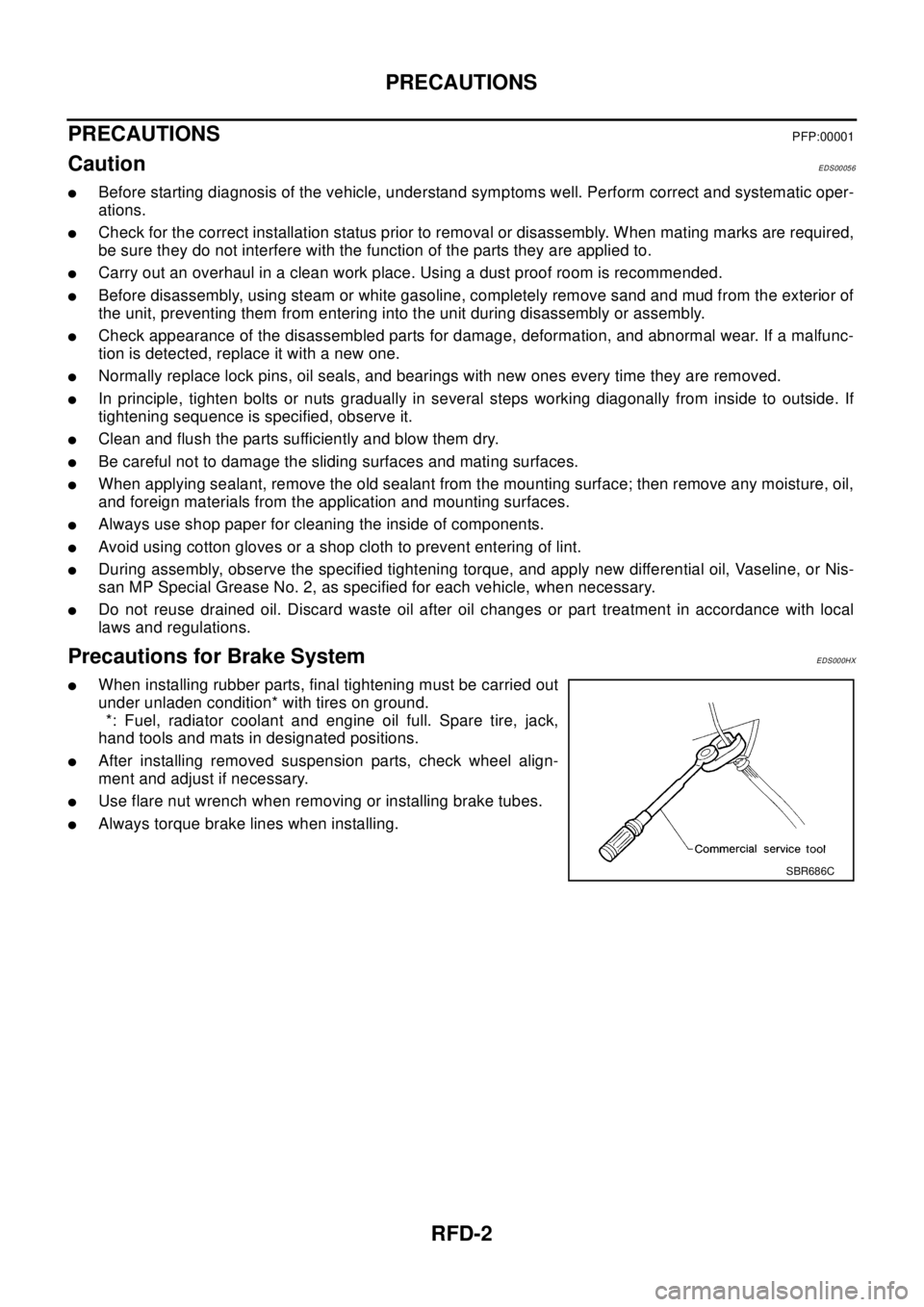
Precautions for Brake SystemEDS000HX
lWhen installing rubber parts, final tightening must be carried out
under unladen condition* with tires on ground.
*: Fuel, radiator coolant and engine oil full. Spare tire, jack,
hand tools and mats in designated positions.
lAfter installing removed suspension parts, check wheel align-
ment and adjust if necessary.
lUse flare nut wrench when removing or installing brake tubes.
lAlways torque brake lines when installing.
SBR686C