2003 NISSAN X-TRAIL FL fuel system
[x] Cancel search: FL fuel systemPage 2258 of 3066

PRECAUTIONS
GI-5
lUse only the fluids and lubricants specified in this manual.
lUse approved bonding agent, sealants or their equivalents when required.
lUse tools and recommended special tools where specified for safe and efficient service repairs.
lWhen repairing the fuel, oil, water, vacuum or exhaust systems, check all affected lines for leaks.
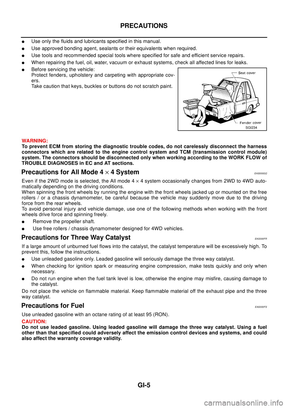
lBefore servicing the vehicle:
Protect fenders, upholstery and carpeting with appropriate cov-
ers.
Take caution that keys, buckles or buttons do not scratch paint.
WA RN ING:
To prevent ECM from storing the diagnostic trouble codes, do not carelessly disconnect the harness
connectors which are related to the engine control system and TCM (transmission control module)
system. The connectors should be disconnected only when working according to the WORK FLOW of
TROUBLE DIAGNOSES in EC and AT sections.
Precautions for All Mode 4´4 SystemEAS000GQ
Even if the 2WD mode is selected, the All mode 4´4 system occasionally changes from 2WD to 4WD auto-
matically depending on the driving conditions.
When spinning the front wheels by running the engine with the front wheels jacked up or mounted on the free
rollers / or a chassis dynamometer, be careful because the vehicle may suddenly move due to the driving
force from the rear wheels.
To avoid personal injury and vehicle damage, use one of the following methods when working with the front
wheels drive force and spinning freely.
lRemove the propeller shaft.
lUse free rollers / chassis dynamometer designed for 4WD vehicles.
Precautions for Three Way CatalystEAS000FR
If a large amount of unburned fuel flows into the catalyst, the catalyst temperature will be excessively high. To
prevent this, follow the instructions.
lUse unleaded gasoline only. Leaded gasoline will seriously damage the three way catalyst.
lWhen checking for ignition spark or measuring engine compression, make tests quickly and only when
necessary.
lDo not run engine when the fuel tank level is low, otherwise the engine may misfire, causing damage to
the catalyst.
Do not place the vehicle on flammable material. Keep flammable material off the exhaust pipe and the three
way catalyst.
Precautions for FuelEAS000FS
Use unleaded gasoline with an octane rating of at least 95 (RON).
CAUTION:
Do not use leaded gasoline. Using leaded gasoline will damage the three way catalyst. Using a fuel
other than that specified could adversely affect the emission control devices and systems, and could
also affect the warranty coverage validity.
SGI234
Page 2259 of 3066

GI-6
PRECAUTIONS
Precautions for Multiport Fuel Injection System or Engine Control System
EAS000FT
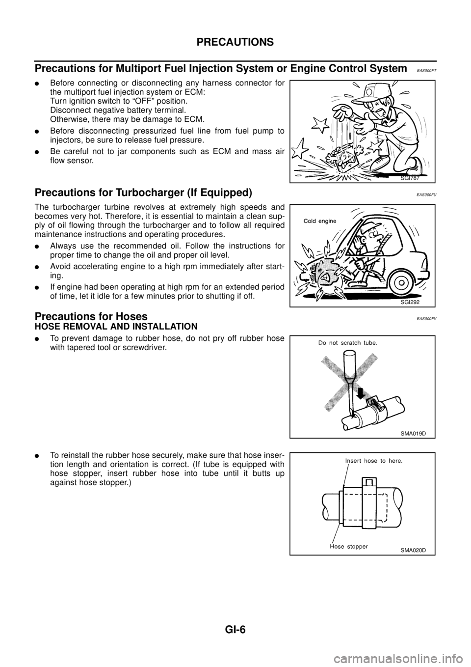
lBefore connecting or disconnecting any harness connector for
the multiport fuel injection system or ECM:
Turn ignition switch to “OFF” position.
Disconnect negative battery terminal.
Otherwise, there may be damage to ECM.
lBefore disconnecting pressurized fuel line from fuel pump to
injectors, be sure to release fuel pressure.
lBe careful not to jar components such as ECM and mass air
flow sensor.
Precautions for Turbocharger (If Equipped)EAS000FU
The turbocharger turbine revolves at extremely high speeds and
becomes very hot. Therefore, it is essential to maintain a clean sup-
ply of oil flowing through the turbocharger and to follow all required
maintenance instructions and operating procedures.
lAlways use the recommended oil. Follow the instructions for
proper time to change the oil and proper oil level.
lAvoid accelerating engine to a high rpm immediately after start-
ing.
lIf engine had been operating at high rpm for an extended period
of time, let it idle for a few minutes prior to shutting if off.
Precautions for HosesEAS000FV
HOSE REMOVAL AND INSTALLATION
lTo prevent damage to rubber hose, do not pry off rubber hose
with tapered tool or screwdriver.
lTo reinstall the rubber hose securely, make sure that hose inser-
tion length and orientation is correct. (If tube is equipped with
hose stopper, insert rubber hose into tube until it butts up
against hose stopper.)
SGI787
SGI292
SMA019D
SMA020D
Page 2300 of 3066

TERMINOLOGY
GI-47
TERMINOLOGYPFP:00011
SAE J1930 Terminology ListEAS000GH
All emission related terms used in this publication in accordance with SAE J1930 are listed. Accordingly, new
terms, new acronyms/abbreviations and old terms are listed in the following chart.
NEW TERMNEW ACRONYM /
ABBREVIATIONOLD TERM
Air cleaner ACL Air cleaner
Barometric pressure BARO ***
Barometric pressure sensor-BCDD BAROS-BCDD BCDD
Camshaft position CMP ***
Camshaft position sensor CMPS Crank angle sensor
Canister *** Canister
Carburetor CARB Carburetor
Charge air cooler CAC Intercooler
Closed loop CL Closed loop
Closed throttle position switch CTP switch Idle switch
Clutch pedal position switch CPP switch Clutch switch
Continuous fuel injection system CFI system ***
Continuous trap oxidizer system CTOX system ***
Crankshaft position CKP ***
Crankshaft position sensor CKPS ***
Data link connector DLC ***
Data link connector for CONSULT-II DLC for CONSULT-II Diagnostic connector for CONSULT-II
Diagnostic test mode DTM Diagnostic mode
Diagnostic test mode selector DTM selector Diagnostic mode selector
Diagnostic test mode I DTM I Mode I
Diagnostic test mode II DTM II Mode II
Diagnostic trouble code DTC Malfunction code
Direct fuel injection system DFI system ***
Distributor ignition system DI system Ignition timing control
Early fuel evaporation-mixture heater EFE-mixture heater Mixture heater
Early fuel evaporation system EFE system Mixture heater control
Electrically erasable programmable read
only memoryEEPROM ***
Electronic ignition system EI system Ignition timing control
Engine control EC ***
Engine control module ECM ECCS control unit
Engine coolant temperature ECT Engine temperature
Engine coolant temperature sensor ECTS Engine temperature sensor
Engine modification EM ***
Engine speed RPM Engine speed
Erasable programmable read only memory EPROM ***
Evaporative emission canister EVAP canister Canister
Evaporative emission system EVAP system Canister control solenoid valve
Exhaust gas recirculation valve EGR valve EGR valve
Page 2301 of 3066

GI-48
TERMINOLOGY
Exhaust gas recirculation control-BPT
valveEGRC-BPT valve BPT valve
Exhaust gas recirculation control-solenoid
valveEGRC-solenoid valve EGR control solenoid valve
Exhaust gas recirculation temperature sen-
sor
EGRT sensor Exhaust gas temperature sensor
EGR temperature sensor
Flash electrically erasable programmable
read only memoryFEEPROM ***
Flash erasable programmable read only
memoryFEPROM ***
Flexible fuel sensor FFS ***
Flexible fuel system FF system ***
Fuel pressure regulator *** Pressure regulator
Fuel pressure regulator control solenoid
valve*** PRVR control solenoid valve
Fuel trim FT ***
Heated Oxygen sensor HO2S Exhaust gas sensor
Idle air control system IAC system Idle speed control
Idle air control valve-air regulator IACV-air regulator Air regulator
Idle air control valve-auxiliary air control
valveIACV-AAC valve Auxiliary air control (AAC) valve
Idle air control valve-FICD solenoid valve IACV-FICD solenoid valve FICD solenoid valve
Idle air control valve-idle up control sole-
noid valveIACV-idle up control solenoid valve Idle up control solenoid valve
Idle speed control-FI pot ISC-FI pot FI pot
Idle speed control system ISC system ***
Ignition control IC ***
Ignition control module ICM ***
Indirect fuel injection system IFI system ***
Intake air IA Air
Intake air temperature sensor IAT sensor Air temperature sensor
Knock *** Detonation
Knock sensor KS Detonation sensor
Malfunction indicator lamp MIL Check engine light
Manifold absolute pressure MAP ***
Manifold absolute pressure sensor MAPS ***
Manifold differential pressure MDP ***
Manifold differential pressure sensor MDPS ***
Manifold surface temperature MST ***
Manifold surface temperature sensor MSTS ***
Manifold vacuum zone MVZ ***
Manifold vacuum zone sensor MVZS ***
Mass air flow sensor MAFS Air flow meter
Mixture control solenoid valve MC solenoid valve Air-fuel ratio control solenoid valve
Multiport fuel injection System MFI system Fuel injection controlNEW TERMNEW ACRONYM /
ABBREVIATIONOLD TERM
Page 2302 of 3066

TERMINOLOGY
GI-49
Nonvolatile random access memory NVRAM ***
On board diagnostic system OBD system Self-diagnosis
Open loop OL Open loop
Oxidation catalyst OC Catalyst
Oxidation catalytic converter system OC system ***
Oxygen sensor O2S Exhaust gas sensor
Park position switch *** Park switch
Park/neutral position switch PNP switchPark/neutral switch
Inhibitor switch
Neutral position switch
Periodic trap oxidizer system PTOX system ***
Positive crankcase ventilation PCV Positive crankcase ventilation
Positive crankcase ventilation valve PCV valve PCV valve
Powertrain control module PCM ***
Programmable read only memory PROM ***
Pulsed secondary air injection control sole-
noid valvePAIRC solenoid valve AIV control solenoid valve
Pulsed secondary air injection system PAIR system Air induction valve (AIV) control
Pulsed secondary air injection valve PAIR valve Air induction valve
Random access memory RAM ***
Read only memory ROM ***
Scan tool ST ***
Secondary air injection pump AIR pump ***
Secondary air injection system AIR system ***
Sequential multiport fuel injection system SFI system Sequential fuel injection
Service reminder indicator SRI ***
Simultaneous multiport fuel injection sys-
tem*** Simultaneous fuel injection
Smoke puff limiter system SPL system ***
Supercharger SC ***
Supercharger bypass SCB ***
System readiness test SRT ***
Thermal vacuum valve TVV Thermal vacuum valve
Three way catalyst TWC Catalyst
Three way catalytic converter system TWC system ***
Three way + oxidation catalyst TWC + OC Catalyst
Three way + oxidation catalytic converter
systemTWC + OC system ***
Throttle body TBThrottle chamber
SPI body
Throttle body fuel injection system TBI system Fuel injection control
Throttle position TP Throttle position
Throttle position sensor TPS Throttle sensor
Throttle position switch TP switch Throttle switchNEW TERMNEW ACRONYM /
ABBREVIATIONOLD TERM
Page 2360 of 3066

IDX-3
A
C
D
E
F
G
H
I
J
K
L B
IDX
ALPHABETICAL INDEX
Brake fluid level and line check ...........................BR-9
Brake hydraulic line ...........................................BR-11
Brake inspection ................................................MA-39
Brake lines and cables inspection .....................MA-39
Brake master cylinder ........................................BR-13
Brake pedal .........................................................BR-6
Brake switch ........................EC-329,EC-562,EC-810
BRK/SW - Wiring diagram ...EC-330,EC-564,EC-811
Bulb specifications ..............................................LT-67
Bumper, front .........................................................EI-6
Bumper, rear ..........................................................EI-9
C
Camshaft inspection(QR20DE) .........................EM-38
Camshaft inspection(YD22DDTi) ....................EM-150
Camshaft position sensor (CMPS) ..................EC-739
Camshaft position sensor (PHASE) ..EC-223,EC-507
Camshaft(QR20DE) ..........................................EM-33
Camshaft(YD22DDTi) ......................................EM-149
CAN - Wiring diagramEC-115,EC-461,LAN-6,LAN-12
CAN (Controller Area Network) .........AT-129,AT-351,
LAN-3
,LAN-5,LAN-11
CAN Communication ..........................................TF-53
CAN communicationEC-28,EC-114,EC-393,EC-460,
AT-129
,AT-351,BRC-53,BRC-59,BRC-90,BRC-108,
LAN-3
,LAN-5,LAN-11
Canister-See EVAP canister .............EC-374,EC-649
CHARGE - Wiring diagram ................................SC-13
Charging system ................................................SC-12
Chassis and body maintenance ........................MA-35
CHIME - Wiring diagram .....................................DI-54
CIGAR - Wiring diagram ..................................WW-25
Cigarette lighter ...............................................WW-25
Circuit breaker ...................................................PG-12
CKPS - Wiring diagram ...................................EC-736
Clearance lamp ........................................LT-4,LT-40
Clock ...................................................................DI-60
CLOCK - Wiring diagram ....................................DI-60
Closed loop control ..............................EC-25,EC-390
Clutch cover .......................................................CL-15
Clutch disc .........................................................CL-15
Clutch master cylinder .........................................CL-9
Clutch operating cylinder ...................................CL-11
Clutch pedal .........................................................CL-5
Clutch release bearing .......................................CL-13
Clutch release mechanism ................................CL-13
Clutch withdrawal lever ......................................CL-13
CMPS - Wiring diagram ...................................EC-741
Coil spring (rear) ...............................................RSU-8
Collision diagnosis ...........................................SRS-46
Combination meter .....................................DI-4,DI-22
Combination switch ................................LT-24,LT-44
Common rail fuel pressure sensor ...................EC-723
Component Location (auto A/C) .........ATC-31,MTC-4
Compression pressure(QR20DE) ......................EM-52
Compression pressure(YD22DDTi) .................EM-173
Compressor clutch removal and installation ..ATC-129
Compressor special service tool ......................ATC-11
Condenser .....................................................ATC-138
Connecting rod bearing clearance(QR20DE) ...EM-83
Connecting rod bearing clearance(YD22DDTi)EM-206
Connecting rod bushing clearance(QR20DE) ..EM-83
Connecting rod bushing clearance(YD22DDTi)EM-200
Connecting rod(QR20DE) .................................EM-82
Connecting rod(YD22DDTi) ..............EM-198,EM-202
Console box - See Instrument panel ..........IP-3,IP-10
CONSULT for engine ............EC-86,EC-434,EC-691
CONSUT for VDC ...........................................BRC-77
Control unit .....................................ATC-104,MTC-19
Control units (terminal arrangement) .................PG-73
Controller Area Network (CAN) ........AT-129,AT-351,
LAN-3
,LAN-5,LAN-11
Converter housing installation ...........AT-459,AT-556
COOL/F - Wiring diagram ...EC-315,EC-552,EC-763
Coolant mixture ratio .........................................MA-19
Coolant replacement(QR20DE) ........................MA-20
Coolant replacement(YD22DDTi) .....................MA-27
Cooling circuit (engine)(QR20DE) ......................CO-7
Cooling circuit (engine)(YD22DDTi) .................CO-28
Cooling fan control system(QR20DE) ...............CO-13
Cooling fan motor ..............................EC-324,EC-561
Cooling fan relay ................................EC-324,EC-561
Cooling fan(QR20DE) .......................................CO-13
Cooling fan(YD22DDTi) ....................................CO-34
Coupling sleeve (M/T) ...........................MT-19,MT-24
Cowl top ..............................................................EI-12
Cowl top cover ....................................................EI-12
Crankcase ventilation system ..........................EC-663
Crankcase ventilation system - See Positive crankcase
ventilation ...........................................EC-375
,EC-650
Crankshaft position sensor (POS) .....EC-217,EC-501
Crankshaft position sensor (TDC) ...................EC-734
Crankshaft(QR20DE) ........................................EM-65
Crankshaft(YD22DDTi) ...................................EM-200
CRFPS - Wiring diagram .................................EC-724
Cylinder block boring(QR20DE) .......................EM-86
Cylinder block boring(YD22DDTi) ...................EM-204
Cylinder block(QR20DE) ..................................EM-64
Cylinder block(YD22DDTi) ..............................EM-188
Cylinder head bolt tightening(QR20DE) ...........EM-54
Cylinder head bolt tightening(YD22DDTi) .......EM-175
Cylinder head gasket selection(YD22DDTi) ...EM-175
Cylinder head(QR20DE) ...................................EM-52
Cylinder head(YD22DDTi) ..............................EM-173
D
Data link connector ............................EC-371
,EC-646
Data link connector for Consult ...........EC-88,EC-435,
EC-691
Daytime light system .............................................LT-9
Daytime running light - See Daytime light systemLT-9
DEF - Wiring diagram .......................................GW-10
Desiccant Assembly .......................ATC-27,ATC-140
Diagnosis sensor unit .....................................SRS-39
Page 2361 of 3066

IDX-4
ALPHABETICAL INDEX
Diagnostic trouble code (DTC) ........................EC-666
Diagnostic trouble code (DTC) for OBD systemEC-12,
EC-38
,EC-379,EC-401,EC-654
Diagnostic trouble code (DTC) inspection priority chart
EC-61
,EC-410
Differential gear (FF M/T) .....................MT-22,MT-27
DLC - Wiring diagram ........................EC-371,EC-646
Door glass ...........................................GW-41,GW-43
Door glass Fitting Adjustment .............GW-41,GW-43
Door lock .................................................BL-54,BL-57
Door mirror ........................................................GW-46
Door trim .............................................................EI-23
Door, front ............................................................BL-8
Door, rear .............................................................BL-8
Drive belt inspection(QR20DE) .........................MA-20
Drive belt inspection(YD22DDTi) ......................MA-27
Drive belt(QR20DE) ..........................................EM-13
Drive belt(YD22DDTi) .....................................EM-110
Drive shaft (front) .............................................FAX-11
Drive shaft (rear) ...............................................RAX-9
Driver air bag ..................................................SRS-27
Dropping resistor (A/T) ......................AT-192,AT-442
DTC work support ..............................................EC-95
DTRL - Wiring diagram .........................................LT-9
Dual pressure switch ........ATC-16,ATC-81,ATC-138
Duct and grilles ...............................ATC-121,MTC-29
E
ECM input/output signal .......................EC-79
,EC-427
ECM power supplyEC-108,EC-256,EC-454,EC-530,
EC-700
ECM relay ........................................................EC-790
ECM/PW - Wiring diagram .................EC-257,EC-531
ECMRLY - Wiring diagram ..............................EC-791
ECTS - Wiring diagram .......EC-143,EC-472,EC-712
EDU - Wiring diagram ......................................EC-756
EGR function ...................................................EC-803
EGR volume control valve ...............................EC-803
EGRC/V - Wiring diagram ................................EC-805
Electric sun roof ...................................................RF-2
Electric throttle control actuator ........EC-271,EC-273,
EC-534
,EC-536
Electrical unit .....................................................PG-73
Electrical units location ......................................PG-64
Electronic drive unit (EDU) ..............................EC-754
Electronic fuel injection pump(YD22DDTi) .....EM-138
Electronic ignition (EI) system .............EC-27,EC-392
Engine control circuit diagramEC-77,EC-425,EC-683
Engine control component parts location ..........EC-73,
EC-421
Engine control module (ECM) ...........EC-249,EC-523,
EC-788
Engine control system diagram and chart ........EC-22,
EC-387
,EC-659
Engine coolant temperature sensor (ECTS) ...EC-141,
EC-470
,EC-711
Engine coolant(QR20DE) ...................................CO-9
Engine coolant(YD22DDTi) ..............................CO-30
Engine fail-safe system .......................EC-62,EC-411
Engine oil filter replacement(QR20DE) .............MA-24
Engine oil filter replacement(YD22DDTi) ..........MA-33
Engine oil replacement(QR20DE) ....................MA-24
Engine oil replacement(YD22DDTi) ..................MA-32
Engine oil(QR20DE) ............................................LU-7
Engine oil(YD22DDTi) .......................................LU-18
Engine removal(QR20DE) ................................EM-61
Engine removal(YD22DDTi) ...........................EM-184
EVAP canister purge volume control solenoid valve ....
EC-233
,EC-372,EC-601,EC-649
EVAP vapor lines inspection(QR20DE) ............MA-26
Evaporative emission (EVAP) systemEC-372,EC-647
Evaporator ....................................................ATC-139
Exhaust manifold(QR20DE) .............................EM-22
Exhaust manifold(YD22DDTi) .........................EM-119
Exhaust system ...................................................EX-2
Exhaust system inspection .....................EX-2,MA-35
Expansion valve ............................................ATC-140
ExteriorEI-13,EI-14,EI-16,EI-17,EI-18,EI-19,EI-21,
EI-22
F
F/FOG - Wiring diagram .........................LT-33
,LT-34
F/PUMP - Wiring diagram .................EC-354,EC-629
Fan control amp. .............................ATC-70,ATC-113
Fan switch ........................................ATC-27,MTC-17
FIAR - Wiring diagram .....................................EC-778
Final drive (FF M/T) ..............................MT-22,MT-27
Final drive disassembly ..................................RFD-11
Final drive removal and installation ................RFD-11
Finisher, interior - See Trim ......................EI-23,EI-25
Finisher, rear panel .............................................EI-22
Floor trim .............................................................EI-28
Fluid temperature sensor (A/T) ........................AT-141
Fluids ................................................................MA-17
Fluorescent leak detector .............................ATC-141
Flywheel (clutch) ................................................CL-15
Flywheel runout(QR20DE) ................................EM-89
Flywheel runout(YD22DDTi) ...........................EM-208
Fog lamp, front ...................................................LT-33
Fork rod (M/T) .......................................MT-21,MT-26
Freeze frame data ..............................EC-39,EC-402
FRO2 - Wiring diagram ....................................EC-582
FRO2/H - Wiring diagram ................................EC-569
Front bumper ........................................................EI-6
Front disc brake .................................................BR-21
Front door ............................................................BL-8
Front Door Trim ..................................................EI-23
Front fog lamp ....................................................LT-33
Front passenger air bag ..................................SRS-33
Front seat .............................................................SE-7
Front seat belt ......................................................SB-3
Front seat belt pre-tensioner .....SB-2,SRS-3,SRS-38
Front side air bag ............................................SRS-35
Front suspension ..............................................FSU-5
Page 2362 of 3066

IDX-5
A
C
D
E
F
G
H
I
J
K
L B
IDX
ALPHABETICAL INDEX
Front washer ......................................................WW-4
Front wiper .........................................................WW-4
FTS - Wiring diagram ......................................EC-752
Fuel check valve ..............................................EC-372
Fuel cut control (at no load high engine speed)EC-28,
EC-393
,EC-662
Fuel filler lid ........................................................BL-64
Fuel filter ..........................................................EC-664
Fuel filter replacement(QR20DE) .........................FL-4
Fuel filter replacement(YD22DDTi) .......FL-15,MA-30
Fuel gauge ..................................................DI-4,DI-22
Fuel injection control system ...........................EC-660
Fuel injection system .........................EC-194,EC-200
Fuel injector .....................................................EC-727
Fuel injector adjustment resistor ......................EC-777
Fuel injector and fuel tube(QR20DE) ................EM-29
Fuel injector and fuel tube(YD22DDTi) ............EM-135
Fuel leak ..........................................................EC-781
Fuel line inspection(QR20DE) .................FL-3,MA-23
Fuel line inspection(YD22DDTi) ............FL-14,MA-30
Fuel pressure check ............................EC-34,EC-399
Fuel pressure release ..........................EC-34,EC-399
Fuel pressure relief valve ................................EC-665
Fuel pump ..........................................EC-352,EC-627
Fuel pump and gauge(QR20DE) ..........................FL-4
Fuel system(QR20DE) .........................................FL-3
Fuel system(YD22DDTi) .....................................FL-14
Fuel tank(QR20DE) ..............................................FL-9
Fuel tank(YD22DDTi) .........................................FL-21
Fuel temperature sensor .................................EC-751
Fuse ...................................................................PG-12
Fuse and fusible link box ...................................PG-77
Fusible link .........................................................PG-12
G
Gear components (M/T) .......................MT-19
,MT-24
Generator ..........................................................SC-12
Generator - See Alternator ................................SC-12
Generic scan tool (GST) ....................................EC-96
Glass ..................................................GW-41,GW-43
GLOW - Wiring diagram ..................................EC-797
Glow plug .........................................................EC-796
Glow plug(YD22DDTi) .....................................EM-130
Glow relay ........................................................EC-796
Grease ...............................................................MA-17
Grille - See Exterior .............................................EI-11
Ground distribution ............................................PG-13
G-sensor .............................................................TF-50
H
H/AIM - Wiring diagram ......................................LT-15
H/LAMP - Wiring diagram ...........................LT-4,LT-5
H/MIRROR - Wiring diagram ............................GW-10
Harness connector ............................................PG-70
Harness layout ...................................................PG-29
Headlamp .............................................................LT-4
Headlamp aiming control ....................................LT-15
Headlamp leveler - See Headlamp aiming control .......
LT-15
Headlamp washer ............................................WW-19
Headlining - See Roof trim ..................................EI-29
Heated oxygen sensor 1 ....EC-160,EC-166,EC-174,
EC-284
,EC-290,EC-490,EC-581
Heated oxygen sensor 1 heater .........EC-120,EC-568
Heated oxygen sensor 2 ....EC-181,EC-187,EC-296,
EC-303
,EC-587
Heated oxygen sensor 2 heater .........EC-125,EC-573
Heated seat ...............................................SE-3,SE-5
HEATER - Wiring diagram ................................MTC-6
Heater and cooling unit (Heater core) ............ATC-115
Heater mirror .....................................................GW-10
Heater system - Wiring diagram .......................MTC-6
Heater unit (heater core) ..ATC-120,MTC-23,MTC-26
HFC134a (R134a) system precaution ...............ATC-4
HFC134a (R134a) system service procedureATC-123
HFC134a (R134a) system service tools ..........ATC-12
HFC134a system service equipment precautionATC-8
HO2S1 - Wiring diaram ......EC-122,EC-162,EC-169,
EC-177
,EC-492
HO2S2 - Wiring diagram ....EC-183,EC-190,EC-299,
EC-306
HO2S2H - Wiring diagram ...............................EC-127
Hood ....................................................................BL-4
Horn .................................................................WW-23
HORN - Wiring diagram ...................................WW-23
How to erase DTC ...........................................EC-666
HowtoeraseDTCforOBDsystem .....EC-46,EC-402
I
IATS - Wiring diagram .....................................EC-138
IATSEN - Wiring diagram ................................EC-578
Identification .....................................................ATC-10
Idle air volume learning ........................EC-31,EC-396
Idle speed .............................EC-64,EC-412,EC-672
IGN/SG - Wiring diagram .................................EC-335
Ignition coil .........................................EC-334,EC-592
Ignition coil(QR20DE) .......................................EM-27
Ignition control system .......................EC-334,EC-592
Ignition timing .......................................EC-64,EC-412
IGNSYS - Wiring diagram ................................EC-593
ILL - Wiring diagram ...........................................LT-45
Illumination ..........................................................LT-45
In vehicle sensor ...............ATC-95,ATC-97,ATC-106
INJECT - Wiring diagram ....EC-344,EC-619,EC-730
Injection nozzle(YD22DDTi) ...........................EM-135
Injector ...............................................EC-343,EC-618
Input shaft (FF M/T) ..............................MT-19,MT-24
Instrument panel ...................................................IP-3
INT/L - Wiring diagram ........................................LT-65
Intake air temparature sensor ............EC-136,EC-577
Intake door control linkage adjustment ............ATC-66
Intake door motorATC-64,ATC-112,MTC-10,MTC-22
Intake manifold(QR20DE) .................................EM-17