Page 2116 of 3502
EM-8
[QR]
PREPARATION
PREPARATIONPFP:00002
Special Service ToolsBBS0058O
Tool number
Tool nameDescription
KV10111100
Seal cutterRemoving oil pan (lower and upper) and front
cover, etc.
ST0501S000
Engine stand assembly
1. ST05011000
Engine stand
2. ST05012000
BaseDisassembling and assembling engine
KV10106500
Engine stand shaft
KV10115300
Engine sub-attachment
KV10116200
Valve spring compressor
1. KV10115900
Attachment
2. KV10109220
AdapterDisassembling and assembling valve
mechanism
Part (1) is a component of KV10116200, but
Part (2) is not so.
KV10112100
Angle wrenchTightening bolts for bearing cap, cylinder
head, etc. in angle
KV10117100
Heated oxygen sensor wrenchLoosening or tightening heated oxygen
sensors
For 22 mm (0.87 in) width hexagon nut
S-NT046
NT042
NT028
ZZA1078D
PBIC1650E
S-NT014
NT379
Page 2119 of 3502
PREPARATION
EM-11
[QR]
C
D
E
F
G
H
I
J
K
L
MA
EM
Oxygen sensor thread cleaner Reconditioning the exhaust system threads
before installing a new heated oxygen sensor
(Use with anti-seize lubricant shown below.)
a = 18 mm (0.71 in) dia. for zirconia heated
oxygen sensor
b = 12 mm (0.47 in) dia. for titania heated
oxygen sensor
Anti-seize lubricant (Permatex 133AR
or equivalent meeting MIL
specification MIL-A-907)Lubricating oxygen sensor thread cleaning
tool when reconditioning exhaust system
threads
Manual lift table caddy Removing and installing engine Tool nameDescription
AEM488
AEM489
ZZA1210D
Page 2125 of 3502
AIR CLEANER AND AIR DUCT
EM-17
[QR]
C
D
E
F
G
H
I
J
K
L
MA
EM
AIR CLEANER AND AIR DUCTPFP:16500
Removal and InstallationBBS0058W
REMOVAL
1. Remove air duct (inlet).
2. Disconnect harness connector from mass air flow sensor.
3. Disconnect PCV hose.
4. Remove air cleaner cases (upper and lower) with mass air flow sensor and air duct assembly disconnect-
ing their joints.
�Add mating marks as necessary for easier installation.
5. Remove mass air flow sensor from air cleaner case (upper), as necessary.
CAUTION:
Handle mass air flow sensor with following cares.
�Do not shock it.
�Do not disassemble it.
�Do not touch its sensor.
6. Remove resonator, removing left side fender protector (front), as necessary.
1. Air cleaner case (lower) 2. Air cleaner filter 3. Air cleaner case (upper)
4. O-ring 5. Mass air flow sensor 6. Harness bracket
7. Air duct assembly 8. PCV hose 9. Clip
10. Air duct (inlet) 11. Resonator 12. Bracket
13. Grommet 14. Bracket
PBIC2414E
Page 2128 of 3502
![NISSAN TEANA 2003 Service Manual EM-20
[QR]
INTAKE MANIFOLD
2. Remove engine cover.
CAUTION:
Be careful not to damage or scratch engine cover.
3. Remove air cleaner case (upper) with mass air flow sensor and air duct assembly. Refe](/manual-img/5/57392/w960_57392-2127.png "NISSAN TEANA 2003 Service Manual EM-20
[QR]
INTAKE MANIFOLD
2. Remove engine cover.
CAUTION:
Be careful not to damage or scratch engine cover.
3. Remove air cleaner case (upper) with mass air flow sensor and air duct assembly. Refe")
EM-20
[QR]
INTAKE MANIFOLD
2. Remove engine cover.
CAUTION:
Be careful not to damage or scratch engine cover.
3. Remove air cleaner case (upper) with mass air flow sensor and air duct assembly. Refer to EM-17, "
AIR
CLEANER AND AIR DUCT" .
4. Remove quick connector cap, and disconnect quick connector
at engine side. Refer to EM-34, "
FUEL INJECTOR AND FUEL
TUBE" .
5. Remove electric throttle control actuator with the following procedure:
a. Disconnect harness connector.
b. Loosen mounting bolts in reverse order as shown in the figure,
and remove electric throttle control actuator and gasket.
CAUTION:
�Handle carefully to avoid any shock to electric throttle
control actuator.
�Do not disassemble.
6. Disconnect harness, power steering piping, vacuum hose and PCV hose from intake manifold, and move
them aside.
7. Remove intake manifold support and gasket.
8. Disconnect sub-harness from fuel injector. Refer to EM-34, "
FUEL INJECTOR AND FUEL TUBE" .
9. Remove fuel tube and fuel injector assembly from intake manifold. Refer to EM-34, "
FUEL INJECTOR
AND FUEL TUBE" .
PBIC2423E
PBIC2175E
EMJ1612D
Page 2131 of 3502
EXHAUST MANIFOLD AND THREE WAY CATALYST
EM-23
[QR]
C
D
E
F
G
H
I
J
K
L
MA
EM
EXHAUST MANIFOLD AND THREE WAY CATALYSTPFP:14004
Removal and InstallationBBS0058Z
REMOVAL
1. Remove undercover.
2. Remove drive belt. Refer to EM-14, "
DRIVE BELTS" .
3. Remove exhaust front tube. Refer to EX-2, "
EXHAUST SYSTEM" .
4. Remove alternator. Refer to SC-27, "
CHARGING SYSTEM" .
5. Remove heated oxygen sensors with the following procedure:
a. Put marks to identify installation positions of each heated oxygen sensor.
b. Disconnect harness connector of each heated oxygen sensor, and harness from bracket and middle
clamp.
1. Heated oxygen sensor 1 2.Exhaust manifold and three way cat-
alyst assembly3. Gasket
4. Three way catalyst cover 5. Exhaust manifold cover (lower) 6. Exhaust manifold stay
7. Heated oxygen sensor 2 8. Exhaust manifold cover (upper)
PBIC4678E
Page 2132 of 3502
![NISSAN TEANA 2003 Service Manual EM-24
[QR]
EXHAUST MANIFOLD AND THREE WAY CATALYST
c. Using heated oxygen sensor wrench (SST), remove heated oxy-
gen sensors.
CAUTION:
�Be careful not to damage heated oxygen sensor.
�Discard any h](/manual-img/5/57392/w960_57392-2131.png "NISSAN TEANA 2003 Service Manual EM-24
[QR]
EXHAUST MANIFOLD AND THREE WAY CATALYST
c. Using heated oxygen sensor wrench (SST), remove heated oxy-
gen sensors.
CAUTION:
�Be careful not to damage heated oxygen sensor.
�Discard any h")
EM-24
[QR]
EXHAUST MANIFOLD AND THREE WAY CATALYST
c. Using heated oxygen sensor wrench (SST), remove heated oxy-
gen sensors.
CAUTION:
�Be careful not to damage heated oxygen sensor.
�Discard any heated oxygen sensor which has been
dropped onto a hard surface such as a concrete floor;
replace with a new one.
6. Remove exhaust manifold stay.
7. Remove exhaust manifold cover (upper).
8. Loosen nuts in reverse order as shown in the figure to remove
exhaust manifold and three way catalyst assembly.
NOTE:
Disregard No. 6 and 7 when loosening.
9. Remove gasket.
CAUTION:
Cover engine openings to avoid entry of foreign materials.
10. Remove exhaust manifold cover (lower) and three way catalyst cover from exhaust manifold and three
way catalyst assembly.
INSPECTION AFTER REMOVAL
Surface Distortion
�Using straightedge and feeler gauge, check the surface distor-
tion of exhaust manifold and three way catalyst assembly mating
surface.
�If it exceeds the limit, replace exhaust manifold and three way
catalyst assembly.
INSTALLATION
Note the following, and install in the reverse order of removal.
Exhaust Manifold
�If stud bolts were removed, install them and tighten to the specified torque below.
KBIA0094E
KBIA0045E
Limit : 0.3 mm (0.012 in)
KBIA0046E
: 14.7 N·m (1.5 kg-m, 11 ft-lb)
Page 2133 of 3502
EXHAUST MANIFOLD AND THREE WAY CATALYST
EM-25
[QR]
C
D
E
F
G
H
I
J
K
L
MA
EM
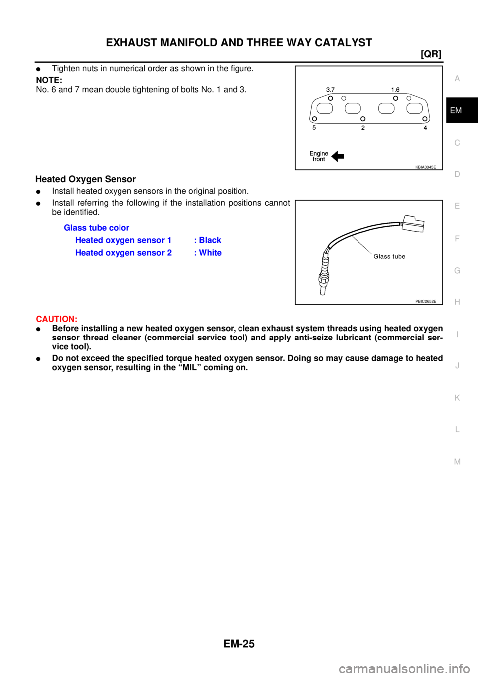
�Tighten nuts in numerical order as shown in the figure.
NOTE:
No. 6 and 7 mean double tightening of bolts No. 1 and 3.
Heated Oxygen Sensor
�Install heated oxygen sensors in the original position.
�Install referring the following if the installation positions cannot
be identified.
CAUTION:
�Before installing a new heated oxygen sensor, clean exhaust system threads using heated oxygen
sensor thread cleaner (commercial service tool) and apply anti-seize lubricant (commercial ser-
vice tool).
�Do not exceed the specified torque heated oxygen sensor. Doing so may cause damage to heated
oxygen sensor, resulting in the “MIL” coming on.
KBIA0045E
Glass tube color
Heated oxygen sensor 1 : Black
Heated oxygen sensor 2 : White
PBIC2652E
Page 2142 of 3502
![NISSAN TEANA 2003 Service Manual EM-34
[QR]
FUEL INJECTOR AND FUEL TUBE
FUEL INJECTOR AND FUEL TUBEPFP:16600
Removal and InstallationBBS00593
CAUTION:
Do not remove or disassemble parts unless instructed as shown in the figure.
REM](/manual-img/5/57392/w960_57392-2141.png "NISSAN TEANA 2003 Service Manual EM-34
[QR]
FUEL INJECTOR AND FUEL TUBE
FUEL INJECTOR AND FUEL TUBEPFP:16600
Removal and InstallationBBS00593
CAUTION:
Do not remove or disassemble parts unless instructed as shown in the figure.
REM")
EM-34
[QR]
FUEL INJECTOR AND FUEL TUBE
FUEL INJECTOR AND FUEL TUBEPFP:16600
Removal and InstallationBBS00593
CAUTION:
Do not remove or disassemble parts unless instructed as shown in the figure.
REMOVAL
WARNING:
�Put a “CAUTION: FLAMMABLE” sign in the workshop.
�Be sure to work in a well ventilated area and furnish workshop with a CO2 fire extinguisher.
�Do not smoke while servicing fuel system. Keep open flames and sparks away from the work area.
1. Release fuel pressure. Refer to EC-49, "
FUEL PRESSURE RELEASE" .
2. Remove air cleaner case (upper) with mass air flow sensor and air duct assembly. Refer to EM-17, "
AIR
CLEANER AND AIR DUCT" .
3. Disconnect quick connectors at engine side and vehicle side as
follows, and remove fuel feed hose.
CAUTION:
Disconnect quick connector by using quick connector
release (SST), not by picking out retainer tabs.
NOTE:
There is quick connector for the engine side and for the vehicle
side, and they have different shapes. But disconnection is same
procedure. The following procedure shows the engine side.
1. Fuel feed hose 2. Quick connector cap (engine side) 3. Quick connector cap (vehicle side)
4. Centralized under-floor piping 5. Sub-harness 6. Fuel tube protector
7. Fuel tube 8. O-ring (black) 9. Clip
10. Fuel injector 11. O-ring (green)
PBIC2178E
PBIC2175E
![NISSAN TEANA 2003 Service Manual EM-8
[QR]
PREPARATION
PREPARATIONPFP:00002
Special Service ToolsBBS0058O
Tool number
Tool nameDescription
KV10111100
Seal cutterRemoving oil pan (lower and upper) and front
cover, etc.
ST0501S000
E](/manual-img/5/57392/w960_57392-2115.png "NISSAN TEANA 2003 Service Manual EM-8
[QR]
PREPARATION
PREPARATIONPFP:00002
Special Service ToolsBBS0058O
Tool number
Tool nameDescription
KV10111100
Seal cutterRemoving oil pan (lower and upper) and front
cover, etc.
ST0501S000
E")
![NISSAN TEANA 2003 Service Manual PREPARATION
EM-11
[QR]
C
D
E
F
G
H
I
J
K
L
MA
EM
Oxygen sensor thread cleaner Reconditioning the exhaust system threads
before installing a new heated oxygen sensor
(Use with anti-seize lubricant](/manual-img/5/57392/w960_57392-2118.png "NISSAN TEANA 2003 Service Manual PREPARATION
EM-11
[QR]
C
D
E
F
G
H
I
J
K
L
MA
EM
Oxygen sensor thread cleaner Reconditioning the exhaust system threads
before installing a new heated oxygen sensor
(Use with anti-seize lubricant")
![NISSAN TEANA 2003 Service Manual AIR CLEANER AND AIR DUCT
EM-17
[QR]
C
D
E
F
G
H
I
J
K
L
MA
EM
AIR CLEANER AND AIR DUCTPFP:16500
Removal and InstallationBBS0058W
REMOVAL
1. Remove air duct (inlet).
2. Disconnect harness connector f](/manual-img/5/57392/w960_57392-2124.png "NISSAN TEANA 2003 Service Manual AIR CLEANER AND AIR DUCT
EM-17
[QR]
C
D
E
F
G
H
I
J
K
L
MA
EM
AIR CLEANER AND AIR DUCTPFP:16500
Removal and InstallationBBS0058W
REMOVAL
1. Remove air duct (inlet).
2. Disconnect harness connector f")
![NISSAN TEANA 2003 Service Manual EXHAUST MANIFOLD AND THREE WAY CATALYST
EM-23
[QR]
C
D
E
F
G
H
I
J
K
L
MA
EM
EXHAUST MANIFOLD AND THREE WAY CATALYSTPFP:14004
Removal and InstallationBBS0058Z
REMOVAL
1. Remove undercover.
2. Remove](/manual-img/5/57392/w960_57392-2130.png "NISSAN TEANA 2003 Service Manual EXHAUST MANIFOLD AND THREE WAY CATALYST
EM-23
[QR]
C
D
E
F
G
H
I
J
K
L
MA
EM
EXHAUST MANIFOLD AND THREE WAY CATALYSTPFP:14004
Removal and InstallationBBS0058Z
REMOVAL
1. Remove undercover.
2. Remove")