Page 1623 of 3502
![NISSAN TEANA 2003 Service Manual REFRIGERANT PRESSURE SENSOR
EC-341
[QR]
C
D
E
F
G
H
I
J
K
L
MA
EC
Specification data are reference values and are measured between each terminal and ground.
CAUTION:
Do not use ECM ground terminals](/manual-img/5/57392/w960_57392-1622.png "NISSAN TEANA 2003 Service Manual REFRIGERANT PRESSURE SENSOR
EC-341
[QR]
C
D
E
F
G
H
I
J
K
L
MA
EC
Specification data are reference values and are measured between each terminal and ground.
CAUTION:
Do not use ECM ground terminals")
REFRIGERANT PRESSURE SENSOR
EC-341
[QR]
C
D
E
F
G
H
I
J
K
L
MA
EC
Specification data are reference values and are measured between each terminal and ground.
CAUTION:
Do not use ECM ground terminals when measuring input/output voltage. Doing so may result in dam-
age to the ECM's transistor. Use a ground other than ECM terminals, such as the ground.
Diagnostic ProcedureBBS005JS
1. CHECK REFRIGERANT PRESSURE SENSOR OVERALL FUNCTION
1. Start engine and warm it up to normal operating temperature.
2. Turn A/C switch and blower fan switch ON.
3. Check voltage between ECM terminal 69 and ground with CON-
SULT-II or tester.
OK or NG
OK >>INSPECTION END
NG >> GO TO 2.
TERMI-
NAL
NO.WIRE
COLORITEM CONDITION DATA (DC Voltage)
46 BR/WSensor power supply
(Refrigerant pressure sen-
sor)[Ignition switch: ON]Approximately 5V
57 BSensor ground
(IAT sensor/ PSP sensor/
Refrigerant pressure sen-
sor)[Engine is running]
�Warm-up condition
�Idle speedApproximately 0V
69 W Refrigerant pressure sensor[Engine is running]
�Warm-up condition
�Both A/C switch and blower fan switch:
ON
(Compressor operates)1.0 - 4.0V
Voltage: 1.0 - 4.0V
MBIB0035E
Page 1624 of 3502
![NISSAN TEANA 2003 Service Manual EC-342
[QR]
REFRIGERANT PRESSURE SENSOR
2. CHECK REFRIGERANT PRESSURE SENSOR POWER SUPPLY CIRCUIT
1. Turn A/C switch and blower fan switch OFF.
2. Stop engine.
3. Disconnect refrigerant pressure sen](/manual-img/5/57392/w960_57392-1623.png "NISSAN TEANA 2003 Service Manual EC-342
[QR]
REFRIGERANT PRESSURE SENSOR
2. CHECK REFRIGERANT PRESSURE SENSOR POWER SUPPLY CIRCUIT
1. Turn A/C switch and blower fan switch OFF.
2. Stop engine.
3. Disconnect refrigerant pressure sen")
EC-342
[QR]
REFRIGERANT PRESSURE SENSOR
2. CHECK REFRIGERANT PRESSURE SENSOR POWER SUPPLY CIRCUIT
1. Turn A/C switch and blower fan switch OFF.
2. Stop engine.
3. Disconnect refrigerant pressure sensor harness connector.
4. Turn ignition switch ON.
5. Check voltage between refrigerant pressure sensor terminal 1
and ground with CONSULT-II or tester.
OK or NG
OK >> GO TO 4.
NG >> GO TO 3.
3. DETECT MALFUNCTIONING PART
Check the following.
�Harness connectors E39, F41
�Harness for open or short between refrigerant pressure sensor and ECM
>> Repair open circuit or short to ground or short to power in harness or connectors.
4. CHECK REFRIGERANT PRESSURE SENSOR GROUND CIRCUIT FOR OPEN AND SHORT
1. Turn ignition switch OFF.
2. Disconnect ECM harness connector.
3. Check harness continuity between refrigerant pressure sensor terminal 3 and ECM terminal 57.
Refer to Wiring Diagram.
4. Also check harness for short to ground and short to power.
OK or NG
OK >> GO TO 6.
NG >> GO TO 5.
5. DETECT MALFUNCTIONING PART
Check the following.
�Harness connectors E39, F41
�Harness for open or short between refrigerant pressure sensor and ECM
>> Repair open circuit or short to ground or short to power in harness or connectors.
PBIB2112E
Voltage: Approximately 5V
PBIB0188E
Continuity should exist.
Page 1628 of 3502
![NISSAN TEANA 2003 Service Manual EC-346
[QR]
SERVICE DATA AND SPECIFICATIONS (SDS)
SERVICE DATA AND SPECIFICATIONS (SDS)PFP:00030
Fuel PressureBBS005JV
Idle Speed and Ignition TimingBBS005JW
*: Under the following conditions:
�Air](/manual-img/5/57392/w960_57392-1627.png "NISSAN TEANA 2003 Service Manual EC-346
[QR]
SERVICE DATA AND SPECIFICATIONS (SDS)
SERVICE DATA AND SPECIFICATIONS (SDS)PFP:00030
Fuel PressureBBS005JV
Idle Speed and Ignition TimingBBS005JW
*: Under the following conditions:
�Air")
EC-346
[QR]
SERVICE DATA AND SPECIFICATIONS (SDS)
SERVICE DATA AND SPECIFICATIONS (SDS)PFP:00030
Fuel PressureBBS005JV
Idle Speed and Ignition TimingBBS005JW
*: Under the following conditions:
�Air conditioner switch: OFF
�Electric load: OFF (Lights, heater fan & rear window defogger)
�Steering wheel: Kept in straight-ahead position
Mass Air Flow SensorBBS005JX
*: Engine is warmed up to normal operating temperature and running under no-load.
Intake Air Temperature SensorBBS005JY
Engine Coolant Temperature SensorBBS005JZ
Crankshaft Position Sensor (POS)BBS005K2
Refer to EC-174, "Component Inspection" .
Camshaft Position Sensor (PHASE)BBS005K3
Refer to EC-182, "Component Inspection" .
Heated Oxygen Sensor 1 HeaterBBS005K0
Heated Oxygen sensor 2 HeaterBBS005K1
Throttle Control MotorBBS005K4
Fuel InjectorBBS005K5
Fuel PumpBBS005K6
Fuel pressure at idle
Approximately 350 kPa (3.5bar, 3.57kg/cm2 , 51psi)
Target idle speed No load* (in N or P position) 700±50 rpm
Air conditioner: ON In N or P position 700 rpm or more
Ignition timing In N or P position 15±5° BTDC
Supply voltageBattery voltage (11 - 14V)
Output voltage at idle0.7 - 1.0V*
Temperature °C (°F) Resistance kΩ
25 (77)1.800 - 2.200
80 (176)0.283 - 0.359
Temperature °C (°F) Resistance kΩ
20 (68)2.1 - 2.9
50 (122)0.68 - 1.00
90 (194)0.236 - 0.260
Resistance [at 25°C (77°F)] 3.3 - 4.0Ω
Resistance [at 25°C (77°F)] 5.0 - 7.0Ω
Resistance [at 25°C (77°F)] Approximately 1 - 15Ω
Resistance [at 10 - 60°C (50 - 140°F)] 11.1 - 14.5Ω
Resistance [at 25°C (77°F)] 0.2 - 5.0Ω
Page 1630 of 3502
EC-348
[VQ]
INDEX FOR DTC
*1: 1st trip DTC No. is the same as DTC No.
*2: In Diagnostic Test Mode II (Self-diagnostic results).
*3: When engine is running.
*4: The troubleshooting for this DTC needs CONSULT-II.P1217 1217 ENG OVER TEMPEC-575
P1225 1225 CTP LEARNINGEC-586
P1226 1226 CTP LEARNINGEC-588
P1229 1229 SENSOR POWER/CIRCEC-590
P1564 1564 ASCD SWEC-595
P1572 1572 ASCD BRAKE SWEC-602
P1574 1574 ASCD VHL SPD SENEC-611
P1610 - P1615 1610 - 1615 NATS MALFUNCTIONBL-139
P1700 1700 CVT C/U FUNCTEC-613
P1706 1706 P-N POS SW/CIRCUITEC-614
P1715 1715 IN PULY SPEEDEC-622
1720 1720 V/SP SEN (A/T OUT)EC-624
P1805 1805 BRAKE SW/CIRCUITEC-626
P2122 2122 APP SEN 1/CIRCEC-631
P2123 2123 APP SEN 1/CIRCEC-631
P2127 2127 APP SEN 2/CIRCEC-638
P2128 2128 APP SEN 2/CIRCEC-638
P2135 2135 TP SENSOREC-645
P2138 2138 APP SENSOREC-652
DTC*1Items
(CONSULT-II screen terms)Reference page
CONSULT-II
ECM*
2
Page 1632 of 3502
EC-350
[VQ]
INDEX FOR DTC
*1: 1st trip DTC No. is the same as DTC No.
*2: In Diagnostic Test Mode II (Self-diagnostic results).
*3: When engine is running.
*4: The troubleshooting for this DTC needs CONSULT-II.MAF SEN/CIRCUIT P0103 0103EC-466
NATS MALFUNCTION P1610 - P1615 1610 - 1615BL-139
NO DTC IS DETECTED.
FURTHER TESTING
MAY BE REQUIRED.No DTC
Flashing*3EC-378
NO DTC IS DETECTED.
FURTHER TESTING
MAY BE REQUIRED.P0000 0000 —
P-N POS SW/CIRCUIT P1706 1706EC-614
PW ST P SEN/CIRC P0550 0550EC-533
SENSOR POWER/CIRC P1229 1229EC-590
TCS C/U FUNCTN P1211 1211EC-573
TCS/CIRC P1212 1212EC-574
TP SEN 1/CIRC P0222 0222EC-505
TP SEN 1/CIRC P0223 0223EC-505
TP SEN 2/CIRC P0122 0122EC-479
TP SEN 2/CIRC P0123 0123EC-479
TP SENSOR P2135 2135EC-645
V/SP SEN (A/T OUT) P1720 1720EC-624
Items
(CONSULT-II screen terms)DTC*1
Reference page
CONSULT-II
ECM*2
Page 1633 of 3502
![NISSAN TEANA 2003 Service Manual PRECAUTIONS
EC-351
[VQ]
C
D
E
F
G
H
I
J
K
L
MA
EC
PRECAUTIONSPFP:00001
Precautions for Supplemental Restraint System (SRS) “AIR BAG” and “SEAT
BELT PRE-TENSIONER”
BBS004XC
The Supplemental](/manual-img/5/57392/w960_57392-1632.png "NISSAN TEANA 2003 Service Manual PRECAUTIONS
EC-351
[VQ]
C
D
E
F
G
H
I
J
K
L
MA
EC
PRECAUTIONSPFP:00001
Precautions for Supplemental Restraint System (SRS) “AIR BAG” and “SEAT
BELT PRE-TENSIONER”
BBS004XC
The Supplemental")
PRECAUTIONS
EC-351
[VQ]
C
D
E
F
G
H
I
J
K
L
MA
EC
PRECAUTIONSPFP:00001
Precautions for Supplemental Restraint System (SRS) “AIR BAG” and “SEAT
BELT PRE-TENSIONER”
BBS004XC
The Supplemental Restraint System such as “AIR BAG” and “SEAT BELT PRE-TENSIONER”, used along
with a front seat belt, helps to reduce the risk or severity of injury to the driver and front passenger for certain
types of collision. Information necessary to service the system safely is included in the SRS and SB section of
this Service Manual.
WARNING:
�To avoid rendering the SRS inoperative, which could increase the risk of personal injury or death
in the event of a collision which would result in air bag inflation, all maintenance must be per-
formed by an authorized NISSAN/INFINITI dealer.
�Improper maintenance, including incorrect removal and installation of the SRS, can lead to per-
sonal injury caused by unintentional activation of the system. For removal of Spiral Cable and Air
Bag Module, see the SRS section.
�Do not use electrical test equipment on any circuit related to the SRS unless instructed to in this
Service Manual. SRS wiring harnesses can be identified by yellow and/or orange harnesses or
harness connectors.
On Board Diagnostic (OBD) System of EngineBBS004XD
The ECM has an on board diagnostic system. It will light up the malfunction indicator (MI) to warn the driver of
a malfunction causing emission deterioration.
CAUTION:
�Be sure to turn the ignition switch OFF and disconnect the negative battery cable before any
repair or inspection work. The open/short circuit of related switches, sensors, solenoid valves,
etc. will cause the MI to light up.
�Be sure to connect and lock the connectors securely after work. A loose (unlocked) connector will
cause the MI to light up due to the open circuit. (Be sure the connector is free from water, grease,
dirt, bent terminals, etc.)
�Certain systems and components, especially those related to OBD, may use a new style slide-
locking type harness connector. For description and how to disconnect, refer to PG-71, "
HAR-
NESS CONNECTOR" .
�Be sure to route and secure the harnesses properly after work. The interference of the harness
with a bracket, etc. may cause the MI to light up due to the short circuit.
�Be sure to erase the unnecessary malfunction information (repairs completed) from the ECM
before returning the vehicle to the customer.
PrecautionBBS004XE
�Always use a 12 volt battery as power source.
�Do not attempt to disconnect battery cables while engine is
running.
�Before connecting or disconnecting the ECM harness con-
nector, turn ignition switch OFF and disconnect negative
battery cable. Failure to do so may damage the ECM
because battery voltage is applied to ECM even if ignition
switch is turned OFF.
�Before removing parts, turn ignition switch OFF and then
disconnect negative battery cable.
SEF289H
Page 1634 of 3502
![NISSAN TEANA 2003 Service Manual EC-352
[VQ]
PRECAUTIONS
�Do not disassemble ECM.
�If a battery cable is disconnected, the memory will return to
the ECM value.
The ECM will now start to self-control at its initial value.
Engine ope](/manual-img/5/57392/w960_57392-1633.png "NISSAN TEANA 2003 Service Manual EC-352
[VQ]
PRECAUTIONS
�Do not disassemble ECM.
�If a battery cable is disconnected, the memory will return to
the ECM value.
The ECM will now start to self-control at its initial value.
Engine ope")
EC-352
[VQ]
PRECAUTIONS
�Do not disassemble ECM.
�If a battery cable is disconnected, the memory will return to
the ECM value.
The ECM will now start to self-control at its initial value.
Engine operation can vary slightly when the terminal is dis-
connected. However, this is not an indication of a malfunc-
tion. Do not replace parts because of a slight variation.
�If the battery is disconnected, the following emission-
related diagnostic information will be lost within 24 hours.
–Diagnostic trouble codes
–1st trip diagnostic trouble codes
–Freeze frame data
–1st trip freeze frame data
�When connecting ECM harness connector, fasten it
securely with levers as far as they will go as shown in the
figure.
�When connecting or disconnecting pin connectors into or
from ECM, take care not to damage pin terminals (bend or
break).
Make sure that there are not any bends or breaks on ECM
pin terminal, when connecting pin connectors.
�Securely connect ECM harness connectors.
A poor connection can cause an extremely high (surge)
voltage to develop in coil and condenser, thus resulting in
damage to ICs.
�Keep engine control system harness at least 10 cm (4 in)
away from adjacent harness, to prevent engine control sys-
tem malfunctions due to receiving external noise, degraded
operation of ICs, etc.
�Keep engine control system parts and harness dry.
�Before replacing ECM, perform “ECM Terminals and Refer-
ence Value” inspection and make sure ECM functions prop-
erly. Refer to EC-415, "
ECM Terminals and Reference Value"
.
�Handle mass air flow sensor carefully to avoid damage.
�Do not disassemble mass air flow sensor.
�Do not clean mass air flow sensor with any type of deter-
gent.
�Do not disassemble electric throttle control actuator.
�Even a slight leak in the air intake system can cause seri-
ous incidents.
�Do not shock or jar the camshaft position sensor (PHASE), crankshaft position sensor (POS).
PBIB1164E
PBIB2466E
PBIB0090E
MEF040D
Page 1636 of 3502
EC-354
[VQ]
PRECAUTIONS
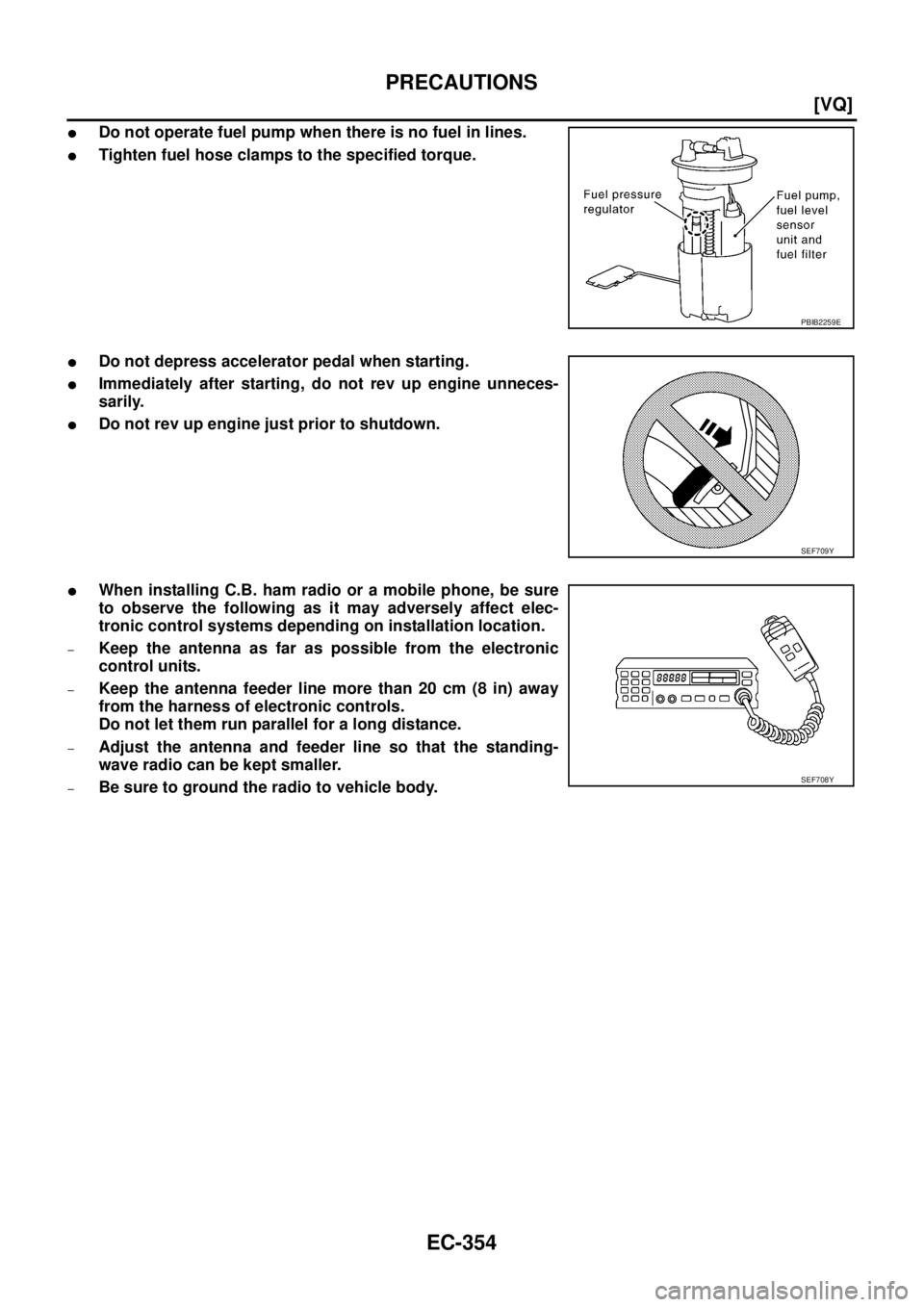
�Do not operate fuel pump when there is no fuel in lines.
�Tighten fuel hose clamps to the specified torque.
�Do not depress accelerator pedal when starting.
�Immediately after starting, do not rev up engine unneces-
sarily.
�Do not rev up engine just prior to shutdown.
�When installing C.B. ham radio or a mobile phone, be sure
to observe the following as it may adversely affect elec-
tronic control systems depending on installation location.
–Keep the antenna as far as possible from the electronic
control units.
–Keep the antenna feeder line more than 20 cm (8 in) away
from the harness of electronic controls.
Do not let them run parallel for a long distance.
–Adjust the antenna and feeder line so that the standing-
wave radio can be kept smaller.
–Be sure to ground the radio to vehicle body.
PBIB2259E
SEF709Y
SEF708Y
![NISSAN TEANA 2003 Service Manual EC-348
[VQ]
INDEX FOR DTC
*1: 1st trip DTC No. is the same as DTC No.
*2: In Diagnostic Test Mode II (Self-diagnostic results).
*3: When engine is running.
*4: The troubleshooting for this DTC needs](/manual-img/5/57392/w960_57392-1629.png "NISSAN TEANA 2003 Service Manual EC-348
[VQ]
INDEX FOR DTC
*1: 1st trip DTC No. is the same as DTC No.
*2: In Diagnostic Test Mode II (Self-diagnostic results).
*3: When engine is running.
*4: The troubleshooting for this DTC needs")
![NISSAN TEANA 2003 Service Manual EC-350
[VQ]
INDEX FOR DTC
*1: 1st trip DTC No. is the same as DTC No.
*2: In Diagnostic Test Mode II (Self-diagnostic results).
*3: When engine is running.
*4: The troubleshooting for this DTC needs](/manual-img/5/57392/w960_57392-1631.png "NISSAN TEANA 2003 Service Manual EC-350
[VQ]
INDEX FOR DTC
*1: 1st trip DTC No. is the same as DTC No.
*2: In Diagnostic Test Mode II (Self-diagnostic results).
*3: When engine is running.
*4: The troubleshooting for this DTC needs")