Page 293 of 3502
REPAIR FOR COMPONENT PARTS
AT-285
D
E
F
G
H
I
J
K
L
MA
B
AT
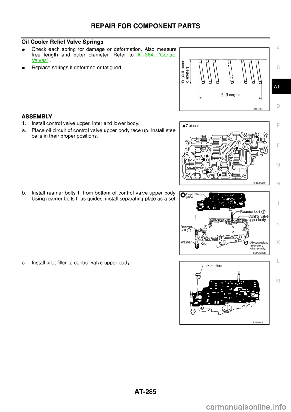
Oil Cooler Relief Valve Springs
�Check each spring for damage or deformation. Also measure
free length and outer diameter. Refer to AT- 3 6 4 , "
Control
Va l v e s" .
�Replace springs if deformed or fatigued.
ASSEMBLY
1. Install control valve upper, inter and lower body.
a. Place oil circuit of control valve upper body face up. Install steel
balls in their proper positions.
b. Install reamer bolts f from bottom of control valve upper body.
Using reamer bolts f as guides, install separating plate as a set.
c. Install pilot filter to control valve upper body.
SAT138D
SCIA3643E
SCIA4980E
SAT074F
Page 294 of 3502
AT-286
REPAIR FOR COMPONENT PARTS
d. Place control valve inter body as shown in figure (side of control
valve lower body face up). Install steel balls in their proper posi-
tions.
e. Install control valve inter body on control valve upper body using
reamer bolts f as guides.
CAUTION:
Be careful not to dislocate or drop steel balls.
f. Install check balls and oil cooler relief valve springs in their
proper positions in control valve lower body.
g. Install bolts e from bottom of control valve lower body. Using
bolts e as guides, install separating plate as a set.
h. Install support plates on control valve lower body.
i. Install control valve lower body on control valve inter body using
reamer bolts f as guides, and tighten reamer bolts f slightly.
SCIA3642E
SCIA4981E
SCIA4885E
SCIA7820E
SCIA7821E
Page 304 of 3502
AT-296
REPAIR FOR COMPONENT PARTS
Reverse ClutchBCS001OO
COMPONENTS
DISASSEMBLY
1. Check operation of reverse clutch
a. Install seal ring onto drum support of oil pump cover and install
reverse clutch assembly. Apply compressed air to oil hole.
b. Check to see that retaining plate moves to snap ring.
c. If retaining plate does not contact snap ring:
�D-ring might be damaged.
�Seal lip might be damaged.
�Fluid might be leaking past piston check ball.
2. Remove snap ring with flat-bladed screwdriver.
3. Remove drive plates, driven plates, retaining plate and dish
plates.
1. Reverse clutch drum 2. D-ring 3. Seal lip
4. Reverse clutch piston 5. Return spring 6. Spring retainer
7. Snap ring 8. Dish plate 9. Driven plate
10. Retaining plate 11. Snap ring 12. Drive plate
SCIA3889E
SCIA3316E
SCIA4886E
Page 305 of 3502

REPAIR FOR COMPONENT PARTS
AT-297
D
E
F
G
H
I
J
K
L
MA
B
AT
4. Set SST on spring retainer, and remove snap ring from reverse
clutch drum while compressing return spring.
CAUTION:
�Set SST directly over return spring.
�Do not expand snap ring excessively.
5. Remove spring retainer and return spring from reverse clutch
drum.
6. Remove reverse clutch piston from reverse clutch drum by turn-
ing it.
7. Remove D-ring and seal lip from reverse clutch piston.
INSPECTION
Reverse Clutch Snap Rings, Return Spring and Spring Retainer
Check for deformation, fatigue or damage. Replace if necessary.
Reverse Clutch Drive Plates
�Check facing for burns, cracks or damage. Replace if necessary.
�Measure thickness of facing.
CAUTION:
�Measure the thickness at 3 locations and find the aver-
age.
�Inspect all drive plates.
�Replace if the thickness is below the allowable limit.
Reverse Clutch Dish Plates
�Check for damage or wear.
�Measure thickness of dish plate. Replace if damaged, worn or
deformed.
Reverse Clutch Piston
�Make sure that check balls are not fixed.
�Apply compressed air to check ball oil hole opposite return spring. Make sure there is no air leakage.
�Apply compressed air to oil hole on return spring side to make sure that air leaks past ball.
SCIA7795E
SCIA3319E
Thickness of drive plate
Standard and allowable limit:
Refer to AT- 3 6 6 , "
REVERSE CLUTCH" .
SAT162D
Thickness of dish plate: 2.96 mm (0.1165 in)
SAT163D
Page 309 of 3502
REPAIR FOR COMPONENT PARTS
AT-301
D
E
F
G
H
I
J
K
L
MA
B
AT
High ClutchBCS001OP
COMPONENTS
DISASSEMBLY
1. Check operation of high clutch.
a. Apply compressed air to oil hole of input shaft assembly (high
clutch drum) with nylon cloth.
CAUTION:
Stop up hole on opposite side of input shaft assembly (high
clutch drum) with nylon cloth.
b. Check to see that retaining plate moves to snap ring.
c. If retaining plate does not contact snap ring:
�D-ring might be damaged.
�Fluid might be leaking past piston check ball.
2. Remove seal rings from input shaft assembly (high clutch drum).
1. Seal ring 2. Driven plate 3. Retaining plate
4. Snap ring 5. Drive plate 6. Snap ring
7. Spring retainer assembly 8. D-ring 9. D-ring
10. High clutch Piston 11. Input shaft assembly (high clutch
drum)
Refer to GI section to make sure icons (symbol marks) in the figure. Refer to GI-10, "
Components" .
SCIA7806E
SAT176D
SCIA4890E
Page 311 of 3502

REPAIR FOR COMPONENT PARTS
AT-303
D
E
F
G
H
I
J
K
L
MA
B
AT
INSPECTION
High Clutch Snap Rings and Spring Retainer Assembly
Check for deformation, fatigue or damage. Replace if necessary.
High Clutch Drive Plates
�Check facing for burns, cracks or damage. Replace if necessary.
�Measure thickness of facing.
CAUTION:
�Measure the thickness at 3 locations and find the aver-
age.
�Inspect all drive plates.
�Replace if the thickness is below the allowable limit.
High Clutch Piston
�Make sure that check balls are not fixed.
�Apply compressed air to check ball oil hole opposite return spring. Make sure there is no air leakage.
�Apply compressed air to oil hole on return spring side to make sure that air leaks past ball.
Seal Ring Clearance
�Install new seal rings onto input shaft assembly (high clutch
drum).
�Measure clearance between seal ring and ring groove.
�If not within allowable limit, replace input shaft assembly (high
clutch drum).Thickness of drive plate
Standard and allowable limit:
Refer to AT- 3 6 6 , "
HIGH CLUTCH" .
SAT162D
Standard clearance and allowable limit:
Refer to AT- 3 6 7 , "
Input Shaft" .
SCIA4901E
Page 315 of 3502

REPAIR FOR COMPONENT PARTS
AT-307
D
E
F
G
H
I
J
K
L
MA
B
AT
Forward and Overrun ClutchesBCS001OQ
COMPONENTS
DISASSEMBLY
1. Check operation of forward clutch and overrun clutch.
a. Install bearing retainer of output shaft on forward clutch drum.
b. Apply compressed air to oil hole of forward clutch drum.
c. Check to see that retaining plate moves to snap ring.
d. If retaining plate does not contact snap ring:
�D-ring might be damaged.
�Seal lip might be damaged.
�Fluid might be leaking past piston check ball.
1. Driven plate 2. Snap ring 3. Dish plate
4. Retaining plate 5. Driven plate 6. Retaining plate
7. Retaining plate 8. Snap ring 9. Drive plate
10. Forward clutch 11. Retaining plate 12. Drive plate
13. Overrun clutch 14. Dish plate 15. Spring retainer assembly
16. Snap ring 17. Overrun clutch piston 18. D-ring
19. Seal lip 20. Forward clutch piston 21. D-ring
22. Seal lip 23. Forward clutch drum
Refer to GI section to make sure icons (symbol marks) in the figure. Refer to GI-10, "
Components" .
SCIA7808E
SAT123F
Page 317 of 3502
 and D-rings (2) from forward clutch piston
(3) and overrun clutch piston (4).
INSPECTION
Snap Rings and Spring Re")
REPAIR FOR COMPONENT PARTS
AT-309
D
E
F
G
H
I
J
K
L
MA
B
AT
10. Remove seal lips (1) and D-rings (2) from forward clutch piston
(3) and overrun clutch piston (4).
INSPECTION
Snap Rings and Spring Retainer Assembly
Check for deformation, fatigue or damage. Replace if necessary.
Forward Clutch and Overrun Clutch Drive Plates
�Check facing for burns, cracks or damage. Replace if necessary.
�Measure thickness of facing.
CAUTION:
�Measure the thickness at 3 locations and find the average.
�Inspect all drive plates.
�Replace if the thickness is below the allowable limit.
Forward Clutch and Overrun Clutch Dish Plates
�Check for damage or wear.
�Measure thickness of dish plate. Replace if damaged, worn or
deformed.
Forward Clutch Drum
�Make sure that check balls are not fixed.
�Apply compressed air to check ball oil hole from outside of for-
ward clutch drum. Make sure air leaks past ball.
�Apply compressed air to oil hole from inside of forward clutch
drum. Make sure there is no air leakage.
SCIA7813E
Thickness of drive plate:
Forward clutch
Standard and allowable limit:
Refer to AT- 3 6 6 , "
FORWARD CLUTCH" .
Overrun clutch
Standard and allowable limit:
Refer to AT- 3 6 6 , "
OVERRUN CLUTCH" .SAT162D
Thickness of dish plate:
Forward clutch: 2.7 mm (0.106 in)
Overrun clutch: 2.3 mm (0.091 in)
SAT163D
SAT213D
. Install steel balls in their proper posi-
tions.
e. Install control")

