Page 3070 of 3502
PG-36
GROUND
ENGINE CONTROL HARNESS/VQ ENGINE MODELS
CKIM0358E
Page 3071 of 3502
GROUND
PG-37
C
D
E
F
G
H
I
J
L
MA
B
PG
ENGINE CONTROL HARNESS/QR ENGINE MODELS
CKIH0286E
Page 3076 of 3502
PG-42
HARNESS
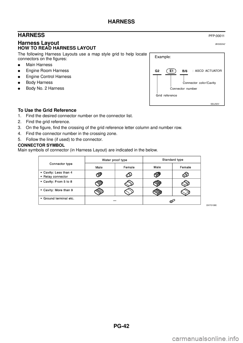
HARNESS PFP:00011
Harness Layout BKS0024Z
HOW TO READ HARNESS LAYOUT
The following Harness Layouts use a map style grid to help locate
connectors on the figures:
�Main Harness
�Engine Room Harness
�Engine Control Harness
�Body Harness
�Body No. 2 Harness
To Use the Grid Reference
1. Find the desired connector number on the connector list.
2. Find the grid reference.
3. On the figure, find the crossing of the grid reference letter column and number row.
4. Find the connector number in the crossing zone.
5. Follow the line (if used) to the connector.
CONNECTOR SYMBOL
Main symbols of connector (in Harness Layout) are indicated in the below.
SEL252V
CKIT0108E
Page 3085 of 3502
HARNESS
PG-51
C
D
E
F
G
H
I
J
L
MA
B
PG
ENGINE CONTROL HARNESS(VQ ENGINE)
TKIM0668E
Page 3087 of 3502
HARNESS
PG-53
C
D
E
F
G
H
I
J
L
MA
B
PG
ENGINE CONTROL HARNESS(QR ENGINE)
TKIM0670E
Page 3097 of 3502
 BKS002FS
Use the chart below to find out what each wiring diagram code stands for.
Refer to the wiring diagram code in the a")
HARNESS
PG-63
C
D
E
F
G
H
I
J
L
MA
B
PG
Wiring Diagram Codes (Cell Codes) BKS002FS
Use the chart below to find out what each wiring diagram code stands for.
Refer to the wiring diagram code in the alphabetical index to find the location (page number) of each wiring
diagram.
Code Section Wiring Diagram Name
A/C ATC Air Conditioner
ABS BRC Anti-Lock Brake System
AFS LT Adaptive Front Lighting System
APPS1 EC Accelerator Pedal Position Sensor
APPS2 EC Accelerator Pedal Position Sensor
APPS3 EC Accelerator Pedal Position Sensor
ASC/BS EC Automatic Speed Control Device (ASCD) Brake Switch
ASC/SW EC Automatic Speed Control Device (ASCD) Steering Switch
ASCBOF EC Automatic Speed Control Device (ASCD) Brake Switch
ASCIND EC Automatic Speed Control Device (ASCD) Indicator
AT/IND DI A/T Indicator Lamp
AUDIO AV Audio
AUT/DP SE Automatic Drive Positioner
AUTO/L LT Auto Light Control
BA/FTS AT A/T Fluid Temperature Sensor and TCM Power Supply
BACK/L LT Back-Up Lamp
BRK/SW EC Brake Switch
CAN AT CAN Communication Line
CAN CVT CAN Communication Line
CAN EC CAN Communication Line
CAN LAN CAN System
CHARGE SC Charging System
CHIME DI Warning Chime
CIGAR WW Cigarette Lighter
COMBSW LT Combination Switch
COMM AV Audio Visual Communication Line
COOL/F EC Cooling Fan Control
CVTIND DI CVT Indicator Lamp
D/LOCK BL Power Door Lock
DEF GW Rear Window Defogger
ECM/PW EC ECM Power Supply for Back-Up
ECTS EC Engine Coolant Temperature Sensor
EMNT EC Electronic Controlled Engine Mount
ENGSS AT Engine Speed Signal
ETC1 EC Electric Throttle Control Function
ETC2 EC Electric Throttle Control Motor Relay
ETC3 EC Electric Throttle Control Motor
F/FOG LT Front Fog Lamp
F/LID BL Fuel Lid Opener
F/PUMP EC Fuel Pump
FRO2 EC Heated Oxygen Sensor 1 Heater
Page 3245 of 3502

CHARGING SYSTEM
SC-27
C
D
E
F
G
H
I
J
L
MA
B
SC
CHARGING SYSTEMPFP:23100
System DescriptionBKS001MJ
The alternator provides DC voltage to operate the vehicle's electrical system and to keep the battery charged.
The voltage output is controlled by the IC regulator.
Power is supplied at all times:
�through 10A fuse (No. 36, located in the fuse and fusible link block)
�to alternator terminal 4 (“S” terminal).
“B” terminal supplies power to charge the battery and operate the vehicle's electrical system. Output voltage is
controlled by the IC regulator at terminal 4 (“S” terminal) detecting the input voltage.
The charging circuit is protected by the 120A fusible link (letter A, located in the fusible link holder).
The alternator is grounded to the engine block.
With the ignition switch in the ON or START position, power is supplied:
�through 10A fuse [No. 14, located in the fuse block (J/B)]
�to combination meter terminal 8 for the charge warning lamp.
Ground is supplied:
�to combination meter terminal 22
�through alternator terminal 3 (“L” terminal)
�to alternator terminal “E”
�through ground E2.
The charge warning lamp will illuminate. When the alternator is providing sufficient voltage with the engine
running, the ground is opened and the charge warning lamp will go off.
If the charge warning lamp illuminates with the engine running, a malfunction is indicated.
MALFUNCTION INDICATOR
The IC regulator warning function activates to illuminate charge warning lamp, if any of the following symp-
toms occur while alternator is operating:
�Excessive voltage is produced.
�No voltage is produced.
Page 3442 of 3502
 controls front")
WW-4
FRONT WIPER AND WASHER SYSTEM
FRONT WIPER AND WASHER SYSTEMPFP:28810
Components Parts and Harness Connector LocationBKS001TF
System DescriptionBKS001TG
�BCM (Body Control Module) controls front wiper low, high and intermittent operation.
�IPDM E/R (Intelligent Power Distribution Module Engine Room) operates front wiper motor according to
CAN communication signals from BCM.
Power is supplied at all times
�to ignition relay (located in IPDM E/R), from battery direct,
�through 50 A fusible link (letter M, located in fuse and fusible link block)
�to BCM terminal 55,
�through 15 A fuse [No. 17, located in fuse block (J/B)]
�to BCM terminal 42,
�through 20 A fuse (No. 73, located in IPDM E/R)
�to front wiper relay (located in IPDM E/R),
�through 15 A fuse (No. 78, located in IPDM E/R)
�to CPU (central processing unit) located in IPDM E/R,
�through 15 A fuse (No. 71, located in IPDM E/R)
�to CPU located in IPDM E/R.
When the ignition switch ON or START position, power is supplied
�to ignition relay (located in IPDM E/R),
�through 10 A fuse [No. 1, located in fuse block (J/B)]
�to BCM terminal 38,
PKIA9954E


TKIM0668E")

TKIM0670E")