Page 1293 of 3502
INDEX FOR DTC
EC-11
[QR]
C
D
E
F
G
H
I
J
K
L
MA
EC
*1: 1st trip DTC No. is the same as DTC No.
*2: In Diagnostic Test Mode II (Self-diagnostic results).
*3: When engine is running, MI may flash.
*4: The troubleshooting for this DTC needs CONSULT-II.P1805 1805 BRAKE SW/CIRCUITEC-245
P2122 2122 APP SEN 1/CIRCEC-251
P2123 2123 APP SEN 1/CIRCEC-251
P2127 2127 APP SEN 2/CIRCEC-258
P2128 2128 APP SEN 2/CIRCEC-258
P2135 2135 TP SENSOREC-265
P2138 2138 APP SENSOREC-272
DTC*1Items
(CONSULT-II screen terms)Reference page
CONSULT-II
ECM*
2
Page 1295 of 3502
INDEX FOR DTC
EC-13
[QR]
C
D
E
F
G
H
I
J
K
L
MA
EC
*1: 1st trip DTC No. is the same as DTC No.
*2: In Diagnostic Test Mode II (Self-diagnostic results).
*3: When engine is running, MI may flash.
*4: The troubleshooting for this DTC needs CONSULT-II.TP SEN 1/CIRC P0223 0223EC-157
TP SEN 2/CIRC P0122 0122EC-136
TP SEN 2/CIRC P0123 0123EC-136
TP SENSOR P2135 2135EC-265
VEH SPEED SEN/CIRC P0500 0500EC-183
V/SP SEN (A/T OUT) P1720 1720EC-243
Items
(CONSULT-II screen terms)DTC*1
Reference page
CONSULT-II
ECM*2
Page 1296 of 3502
![NISSAN TEANA 2003 Service Manual EC-14
[QR]
PRECAUTIONS
PRECAUTIONSPFP:00001
Precautions for Supplemental Restraint System (SRS) “AIR BAG” and “SEAT
BELT PRE-TENSIONER”
BBS005B9
The Supplemental Restraint System such as �](/manual-img/5/57392/w960_57392-1295.png "NISSAN TEANA 2003 Service Manual EC-14
[QR]
PRECAUTIONS
PRECAUTIONSPFP:00001
Precautions for Supplemental Restraint System (SRS) “AIR BAG” and “SEAT
BELT PRE-TENSIONER”
BBS005B9
The Supplemental Restraint System such as �")
EC-14
[QR]
PRECAUTIONS
PRECAUTIONSPFP:00001
Precautions for Supplemental Restraint System (SRS) “AIR BAG” and “SEAT
BELT PRE-TENSIONER”
BBS005B9
The Supplemental Restraint System such as “AIR BAG” and “SEAT BELT PRE-TENSIONER”, used along
with a front seat belt, helps to reduce the risk or severity of injury to the driver and front passenger for certain
types of collision. Information necessary to service the system safely is included in the SRS and SB section of
this Service Manual.
WARNING:
�To avoid rendering the SRS inoperative, which could increase the risk of personal injury or death
in the event of a collision which would result in air bag inflation, all maintenance must be per-
formed by an authorized NISSAN/INFINITI dealer.
�Improper maintenance, including incorrect removal and installation of the SRS, can lead to per-
sonal injury caused by unintentional activation of the system. For removal of Spiral Cable and Air
Bag Module, see the SRS section.
�Do not use electrical test equipment on any circuit related to the SRS unless instructed to in this
Service Manual. SRS wiring harnesses can be identified by yellow and/or orange harnesses or
harness connectors.
On Board Diagnostic (OBD) System of EngineBBS005BA
The ECM has an on board diagnostic system. It will light up the malfunction indicator (MI) to warn the driver of
a malfunction causing emission deterioration.
CAUTION:
�Be sure to turn the ignition switch OFF and disconnect the negative battery cable before any
repair or inspection work. The open/short circuit of related switches, sensors, solenoid valves,
etc. will cause the MI to light up.
�Be sure to connect and lock the connectors securely after work. A loose (unlocked) connector will
cause the MI to light up due to the open circuit. (Be sure the connector is free from water, grease,
dirt, bent terminals, etc.)
�Certain systems and components, especially those related to OBD, may use a new style slide-
locking type harness connector. For description and how to disconnect, refer to PG-71, "
HAR-
NESS CONNECTOR" .
�Be sure to route and secure the harnesses properly after work. The interference of the harness
with a bracket, etc. may cause the MI to light up due to the short circuit.
�Be sure to erase the unnecessary malfunction information (repairs completed) from the ECM
before returning the vehicle to the customer.
PrecautionBBS005BB
�Always use a 12 volt battery as power source.
�Do not attempt to disconnect battery cables while engine is
running.
�Before connecting or disconnecting the ECM harness con-
nector, turn ignition switch OFF and disconnect negative
battery cable. Failure to do so may damage the ECM
because battery voltage is applied to ECM even if ignition
switch is turned OFF.
�Before removing parts, turn ignition switch OFF and then
disconnect negative battery cable.
SEF289H
Page 1297 of 3502
![NISSAN TEANA 2003 Service Manual PRECAUTIONS
EC-15
[QR]
C
D
E
F
G
H
I
J
K
L
MA
EC
�Do not disassemble ECM.
�If a battery cable is disconnected, the memory will return to
the ECM value.
The ECM will now start to self-control at its](/manual-img/5/57392/w960_57392-1296.png "NISSAN TEANA 2003 Service Manual PRECAUTIONS
EC-15
[QR]
C
D
E
F
G
H
I
J
K
L
MA
EC
�Do not disassemble ECM.
�If a battery cable is disconnected, the memory will return to
the ECM value.
The ECM will now start to self-control at its")
PRECAUTIONS
EC-15
[QR]
C
D
E
F
G
H
I
J
K
L
MA
EC
�Do not disassemble ECM.
�If a battery cable is disconnected, the memory will return to
the ECM value.
The ECM will now start to self-control at its initial value.
Engine operation can vary slightly when the terminal is dis-
connected. However, this is not an indication of a malfunc-
tion. Do not replace parts because of a slight variation.
�If the battery is disconnected, the following emission-
related diagnostic information will be lost within 24 hours.
–Diagnostic trouble codes
–1st trip diagnostic trouble codes
–Freeze frame data
–1st trip freeze frame data
�When connecting ECM harness connector, fasten it
securely with levers as far as they will go as shown in the
figure.
�When connecting or disconnecting pin connectors into or
from ECM, take care not to damage pin terminals (bend or
break).
Make sure that there are not any bends or breaks on ECM
pin terminal, when connecting pin connectors.
�Securely connect ECM harness connectors.
A poor connection can cause an extremely high (surge)
voltage to develop in coil and condenser, thus resulting in
damage to ICs.
�Keep engine control system harness at least 10 cm (4 in)
away from adjacent harness, to prevent engine control sys-
tem malfunctions due to receiving external noise, degraded
operation of ICs, etc.
�Keep engine control system parts and harness dry.
�Before replacing ECM, perform “ECM Terminals and Refer-
ence Value” inspection and make sure ECM functions prop-
erly. Refer to EC-415, "
ECM Terminals and Reference Value"
.
�Handle mass air flow sensor carefully to avoid damage.
�Do not disassemble mass air flow sensor.
�Do not clean mass air flow sensor with any type of deter-
gent.
�Do not disassemble electric throttle control actuator.
�Even a slight leak in the air intake system can cause seri-
ous incidents.
�Do not shock or jar the camshaft position sensor (PHASE), crankshaft position sensor (POS).
PBIB1164E
PBIB2466E
PBIB0090E
MEF040D
Page 1299 of 3502
PRECAUTIONS
EC-17
[QR]
C
D
E
F
G
H
I
J
K
L
MA
EC
�Do not depress accelerator pedal when starting.
�Immediately after starting, do not rev up engine unneces-
sarily.
�Do not rev up engine just prior to shutdown.
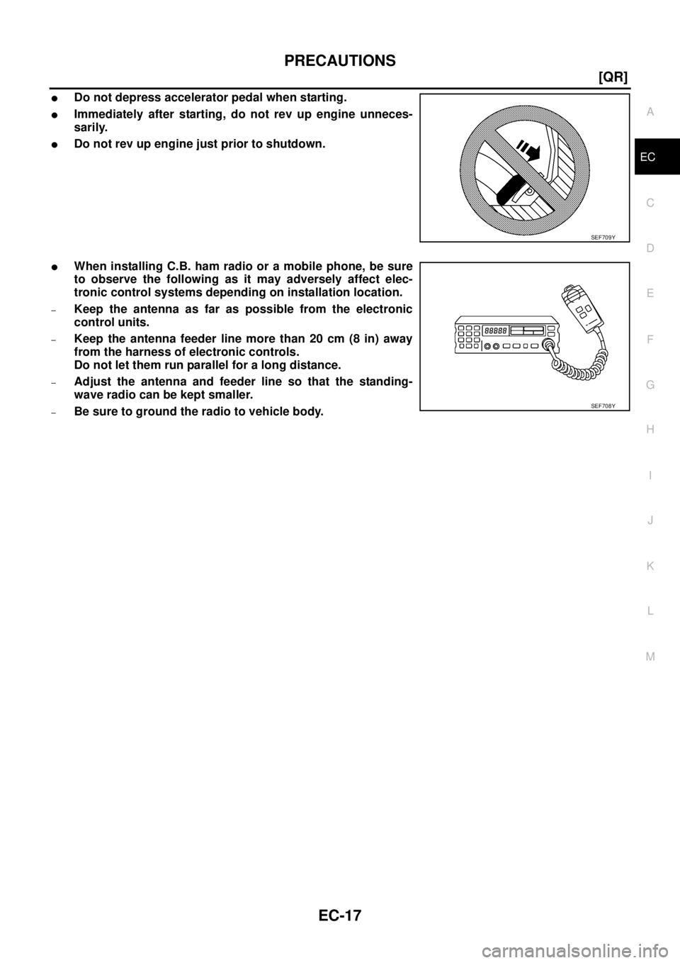
�When installing C.B. ham radio or a mobile phone, be sure
to observe the following as it may adversely affect elec-
tronic control systems depending on installation location.
–Keep the antenna as far as possible from the electronic
control units.
–Keep the antenna feeder line more than 20 cm (8 in) away
from the harness of electronic controls.
Do not let them run parallel for a long distance.
–Adjust the antenna and feeder line so that the standing-
wave radio can be kept smaller.
–Be sure to ground the radio to vehicle body.
SEF709Y
SEF708Y
Page 1301 of 3502
PREPARATION
EC-19
[QR]
C
D
E
F
G
H
I
J
K
L
MA
EC
Commercial Service ToolsBBS005BD
Tool name Description
Quick connector
releaseRemoving fuel tube quick connectors in engine
room
(Available in SEC. 164 of PARTS CATALOG: Part
No. 16441 6N210)
Fuel filler cap adapter Checking fuel tank vacuum relief valve opening
pressure
Socket wrench Removing and installing engine coolant
temperature sensor
Oxygen sensor thread
cleanerReconditioning the exhaust system threads
before installing a new oxygen sensor. Use with
anti-seize lubricant shown below.
a: 18 mm diameter with pitch 1.5 mm for
Zirconia Oxygen Sensor
b: 12 mm diameter with pitch 1.25 mm for
Titania Oxygen Sensor
Anti-seize lubricant
i.e.: (Permatex
TM
133AR or equivalent
meeting MIL
specification MIL-A-
907)Lubricating oxygen sensor thread cleaning tool
when reconditioning exhaust system threads.
PBIC0198E
S-NT653
S-NT705
AEM488
S-NT779
Page 1302 of 3502
EC-20
[QR]
ENGINE CONTROL SYSTEM
ENGINE CONTROL SYSTEMPFP:23710
System DiagramBBS005BE
PBIB3287E
Page 1303 of 3502
![NISSAN TEANA 2003 Service Manual ENGINE CONTROL SYSTEM
EC-21
[QR]
C
D
E
F
G
H
I
J
K
L
MA
EC
Multiport Fuel Injection (MFI) SystemBBS005BF
INPUT/OUTPUT SIGNAL CHART
*1: This sensor is not used to control the engine system under norm](/manual-img/5/57392/w960_57392-1302.png "NISSAN TEANA 2003 Service Manual ENGINE CONTROL SYSTEM
EC-21
[QR]
C
D
E
F
G
H
I
J
K
L
MA
EC
Multiport Fuel Injection (MFI) SystemBBS005BF
INPUT/OUTPUT SIGNAL CHART
*1: This sensor is not used to control the engine system under norm")
ENGINE CONTROL SYSTEM
EC-21
[QR]
C
D
E
F
G
H
I
J
K
L
MA
EC
Multiport Fuel Injection (MFI) SystemBBS005BF
INPUT/OUTPUT SIGNAL CHART
*1: This sensor is not used to control the engine system under normal conditions.
*2: This signal is sent to the ECM through CAN communication line.
*3: ECM determines the start signal status by the signals of engine speed and battery voltage.
SYSTEM DESCRIPTION
The amount of fuel injected from the fuel injector is determined by the ECM. The ECM controls the length of
time the valve remains open (injection pulse duration). The amount of fuel injected is a program value in the
ECM memory. The program value is preset by engine operating conditions. These conditions are determined
by input signals (for engine speed and intake air) from both the crankshaft position sensor and the mass air
flow sensor.
VARIOUS FUEL INJECTION INCREASE/DECREASE COMPENSATION
In addition, the amount of fuel injected is compensated to improve engine performance under various operat-
ing conditions as listed below.
�During warm-up
�When starting the engine
�During acceleration
�Hot-engine operation
�When selector lever is changed from N to D
�High-load, high-speed operation
�During deceleration
�During high engine speed operation
Sensor Input Signal to ECM ECM function Actuator
Crankshaft position sensor (POS)
Camshaft position sensor (PHASE)Engine speed*
3
Piston position
Fuel injection & mixture
ratio controlFuel injector Mass air flow sensor Amount of intake air
Engine coolant temperature sensor Engine coolant temperature
Heated oxygen sensor 1 Density of oxygen in exhaust gas
Throttle position sensor Throttle position
Accelerator pedal position sensor Accelerator pedal position
Park/neutral position (PNP) switch Gear position
Knock sensor Engine knocking condition
Battery
Battery voltage*
3
Power steering pressure sensor Power steering operation
Heated oxygen sensor 2*
1Density of oxygen in exhaust gas
Wheel sensor
Vehicle speed*
2
Air conditioner switch
Air conditioner operation*2
![NISSAN TEANA 2003 Service Manual INDEX FOR DTC
EC-11
[QR]
C
D
E
F
G
H
I
J
K
L
MA
EC
*1: 1st trip DTC No. is the same as DTC No.
*2: In Diagnostic Test Mode II (Self-diagnostic results).
*3: When engine is running, MI may flash.
*4:](/manual-img/5/57392/w960_57392-1292.png "NISSAN TEANA 2003 Service Manual INDEX FOR DTC
EC-11
[QR]
C
D
E
F
G
H
I
J
K
L
MA
EC
*1: 1st trip DTC No. is the same as DTC No.
*2: In Diagnostic Test Mode II (Self-diagnostic results).
*3: When engine is running, MI may flash.
*4:")
![NISSAN TEANA 2003 Service Manual INDEX FOR DTC
EC-13
[QR]
C
D
E
F
G
H
I
J
K
L
MA
EC
*1: 1st trip DTC No. is the same as DTC No.
*2: In Diagnostic Test Mode II (Self-diagnostic results).
*3: When engine is running, MI may flash.
*4:](/manual-img/5/57392/w960_57392-1294.png "NISSAN TEANA 2003 Service Manual INDEX FOR DTC
EC-13
[QR]
C
D
E
F
G
H
I
J
K
L
MA
EC
*1: 1st trip DTC No. is the same as DTC No.
*2: In Diagnostic Test Mode II (Self-diagnostic results).
*3: When engine is running, MI may flash.
*4:")
![NISSAN TEANA 2003 Service Manual PREPARATION
EC-19
[QR]
C
D
E
F
G
H
I
J
K
L
MA
EC
Commercial Service ToolsBBS005BD
Tool name Description
Quick connector
releaseRemoving fuel tube quick connectors in engine
room
(Available in SEC.](/manual-img/5/57392/w960_57392-1300.png "NISSAN TEANA 2003 Service Manual PREPARATION
EC-19
[QR]
C
D
E
F
G
H
I
J
K
L
MA
EC
Commercial Service ToolsBBS005BD
Tool name Description
Quick connector
releaseRemoving fuel tube quick connectors in engine
room
(Available in SEC.")
![NISSAN TEANA 2003 Service Manual EC-20
[QR]
ENGINE CONTROL SYSTEM
ENGINE CONTROL SYSTEMPFP:23710
System DiagramBBS005BE
PBIB3287E](/manual-img/5/57392/w960_57392-1301.png "NISSAN TEANA 2003 Service Manual EC-20
[QR]
ENGINE CONTROL SYSTEM
ENGINE CONTROL SYSTEMPFP:23710
System DiagramBBS005BE
PBIB3287E")