Page 1185 of 3502
SHIFT CONTROL SYSTEM
CVT-179
D
E
F
G
H
I
J
K
L
MA
B
CVT
Checking of CVT PositionBCS001MO
1. Place selector lever in “P” position, and turn ignition switch ON. (Do not start engine.)
2. Make sure selector lever can be shifted to other than “P” position when brake pedal is depressed. Also
make sure selector lever can be shifted from “P” position only when brake pedal is depressed.
3. Move the selector lever and check for excessive effort, sticking, noise or rattle.
4. Confirm the selector lever stops at each position with the feel of engagement when it is moved through all
the positions. Check whether or not the actual position the selector lever is in matches the position shown
by the shift position indicator and the transaxle body.
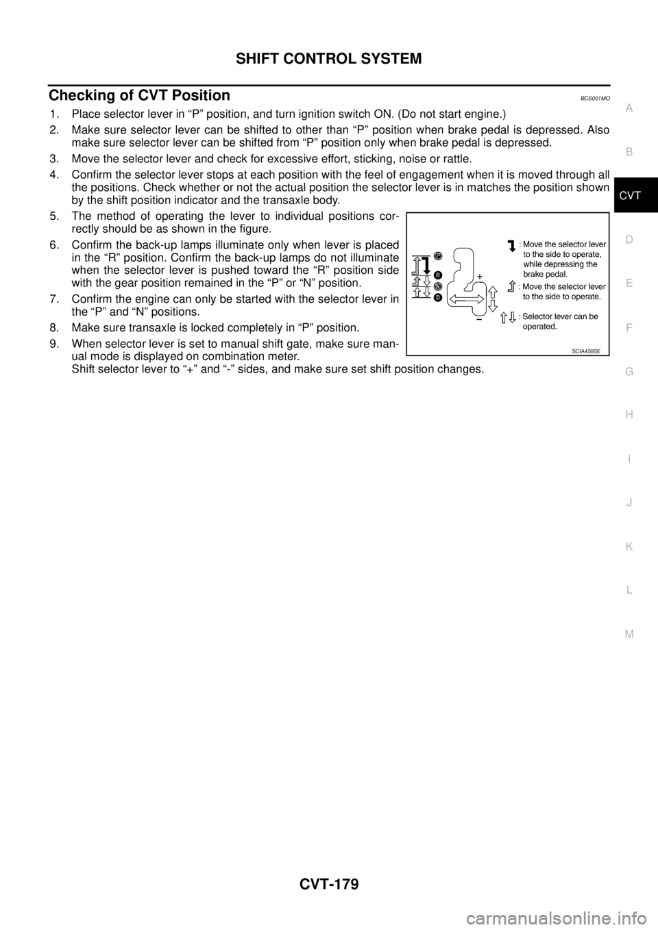
5. The method of operating the lever to individual positions cor-
rectly should be as shown in the figure.
6. Confirm the back-up lamps illuminate only when lever is placed
in the “R” position. Confirm the back-up lamps do not illuminate
when the selector lever is pushed toward the “R” position side
with the gear position remained in the “P” or “N” position.
7. Confirm the engine can only be started with the selector lever in
the “P” and “N” positions.
8. Make sure transaxle is locked completely in “P” position.
9. When selector lever is set to manual shift gate, make sure man-
ual mode is displayed on combination meter.
Shift selector lever to “+” and “-” sides, and make sure set shift position changes.
SCIA4595E
Page 1195 of 3502
CVT FLUID COOLER SYSTEM
CVT-189
D
E
F
G
H
I
J
K
L
MA
B
CVT
CVT FLUID COOLER SYSTEMPFP:21600
CVT Fluid Cooler Removal and InstallationBCS001MX
COMPONENTS
1. Harness bracket 2. CVT fluid cooler inlet tube assembly 3. Transaxle assembly
4. Hose clamp 5. Inlet water hose 6. Hose clamp
7. Outlet water hose 8. Heater hose 9. Hose clamp
10. CVT fluid cooler outlet tube assem-
bly11. CVT fluid cooler valve assembly
A. O-ring
Refer to GI section to make sure icons (symbol marks) in the figure. Refer to GI-10, "
Components" .
However, refer to the following symbols for others.
: Apply engine coolant or equivalent.
SCIA7740E
Page 1196 of 3502
CVT-190
CVT FLUID COOLER SYSTEM
REMOVAL
WARNING:
Never remove the radiator cap when the engine is hot. Serious burns could occur from high pressure
engine coolant escaping from the radiator.
1. Remove engine undercover.
2. Drain engine coolant. Refer to CO-34, "
Changing Engine Coolant" .
CAUTION:
Perform when the engine is cold.
3. Remove air duct (inlet). Refer to EM-131, "
Removal and Installation" .
4. Remove battery. Refer to SC-13, "
Removal and Installation" .
5. Remove air cleaner case (upper and lower), resonator, mass air flow sensor and air duct assembly. Refer
to EM-131, "
Removal and Installation" .
6. Remove fuse and fusible link block from battery bracket.
7. Remove battery bracket.
8. Remove battery bracket mounting.
SCIA2749E
SCIA2750E
SCIA2751E
Page 1198 of 3502
CVT-192
CVT FLUID COOLER SYSTEM
INSTALLATION
Note the following, and install in the reverse order of removal.
�After completing installation, check for engine coolant leakage, engine coolant level, and the positions of
CVT. Refer to CO-34, "
Inspection" and CVT-179, "Checking of CVT Position" .
CAUTION:
�Install hose clamp with tabs aligned with markings of CVT fluid cooler valve assembly and each
hose.
�Do not reuse CVT fluid cooler inlet tube assembly and CVT fluid cooler outlet tube assembly.
�Apply LLC around O-ring when installing CVT fluid cooler inlet tube and CVT fluid cooler outlet
tube assembly to CVT fluid cooler valve assembly.
COMPONENT INSPECTION
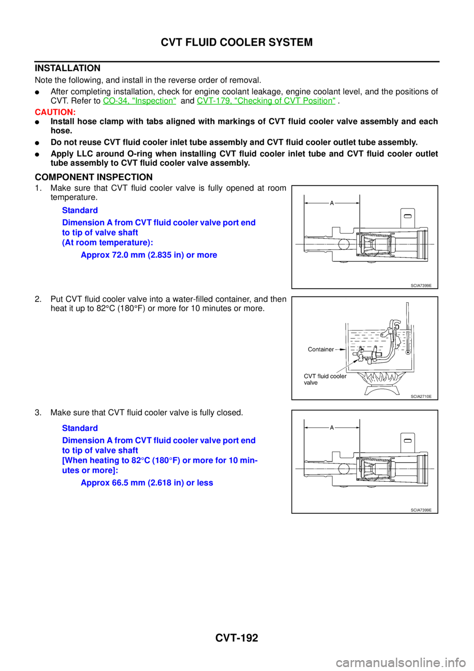
1. Make sure that CVT fluid cooler valve is fully opened at room
temperature.
2. Put CVT fluid cooler valve into a water-filled container, and then
heat it up to 82°C (180°F) or more for 10 minutes or more.
3. Make sure that CVT fluid cooler valve is fully closed.Standard
Dimension A from CVT fluid cooler valve port end
to tip of valve shaft
(At room temperature):
Approx 72.0 mm (2.835 in) or more
SCIA7399E
SCIA2710E
Standard
Dimension A from CVT fluid cooler valve port end
to tip of valve shaft
[When heating to 82°C (180°F) or more for 10 min-
utes or more]:
Approx 66.5 mm (2.618 in) or less
SCIA7399E
Page 1199 of 3502
TRANSAXLE ASSEMBLY
CVT-193
D
E
F
G
H
I
J
K
L
MA
B
CVT
TRANSAXLE ASSEMBLYPFP:32020
Removal and InstallationBCS001N0
COMPONENTS
1. Air breather hose 2. Rear gusset 3. CVT fluid level gauge
4. CVT fluid charging pipe 5. O-ring 6. Fluid cooler tube
7. Copper washer 8. Hose clamp 9. CVT fluid cooler hose
10. CVT fluid cooler hose 11. LH engine mounting bracket 12. LH engine mounting insulator
13. Transaxle assembly
Refer to GI section to make sure icons (symbol marks) in the figure. Refer to GI-10, "
Components" .
However, refer to the following symbols for others.
: For tightening torque, refer to CVT-196, "
INSTALLATION" .
(A) : To radiator
SCIA7899E
Page 1200 of 3502
CVT-194
TRANSAXLE ASSEMBLY
REMOVAL
CAUTION:
The transaxle assembly itself cannot be removed from the vehicle. Remove the transaxle assembly
and engine assembly together from the vehicle.
1. Disconnect the batter cable from the negative terminal.
2. Remove engine undercover.
3. Remove exhaust front tube with power tool. Refer to EX-2, "
Removal and Installation" .
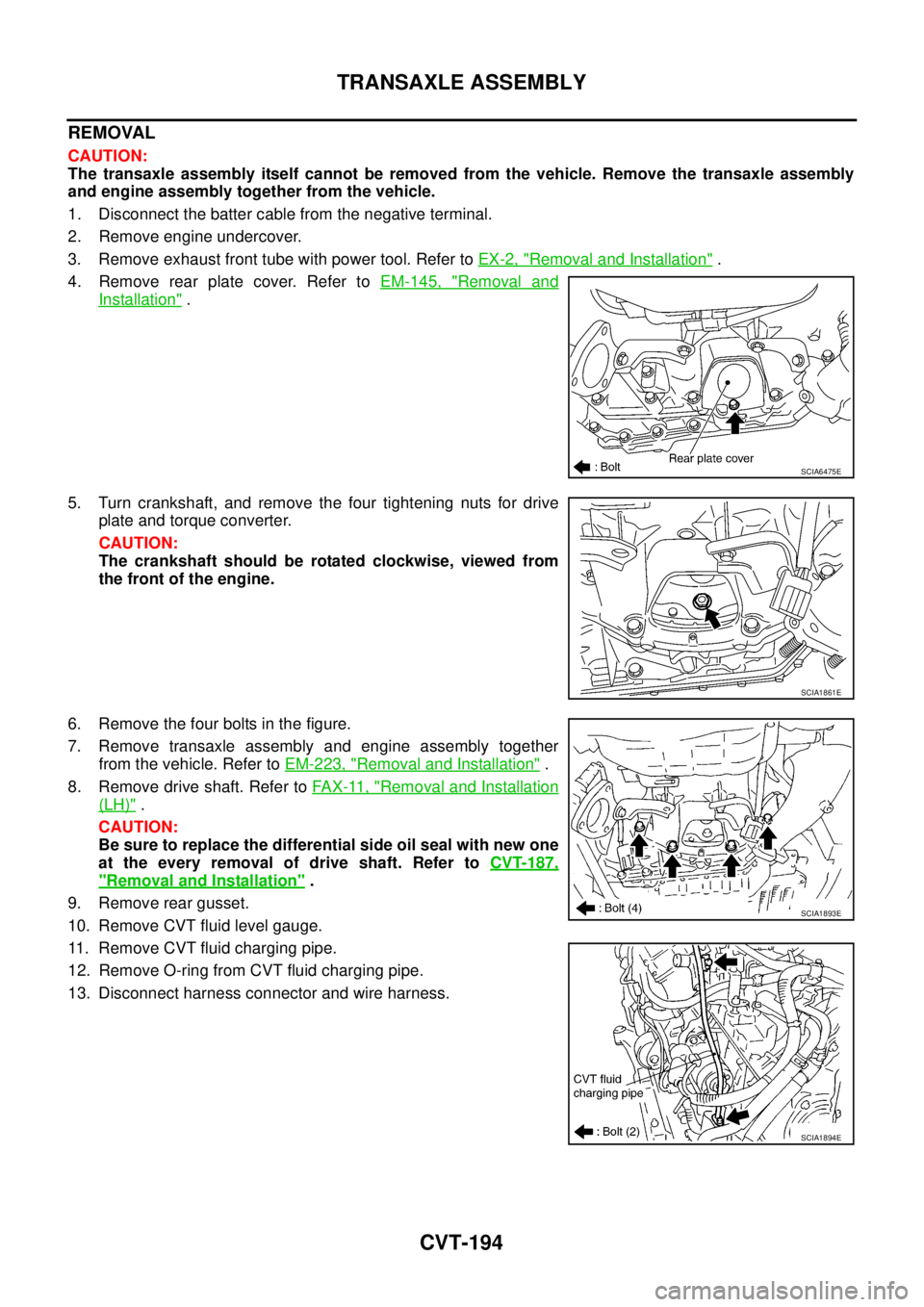
4. Remove rear plate cover. Refer to EM-145, "
Removal and
Installation" .
5. Turn crankshaft, and remove the four tightening nuts for drive
plate and torque converter.
CAUTION:
The crankshaft should be rotated clockwise, viewed from
the front of the engine.
6. Remove the four bolts in the figure.
7. Remove transaxle assembly and engine assembly together
from the vehicle. Refer to EM-223, "
Removal and Installation" .
8. Remove drive shaft. Refer to FA X - 11 , "
Removal and Installation
(LH)" .
CAUTION:
Be sure to replace the differential side oil seal with new one
at the every removal of drive shaft. Refer to CVT-187,
"Removal and Installation" .
9. Remove rear gusset.
10. Remove CVT fluid level gauge.
11. Remove CVT fluid charging pipe.
12. Remove O-ring from CVT fluid charging pipe.
13. Disconnect harness connector and wire harness.
SCIA6475E
SCIA1861E
SCIA1893E
SCIA1894E
Page 1201 of 3502
TRANSAXLE ASSEMBLY
CVT-195
D
E
F
G
H
I
J
K
L
MA
B
CVT
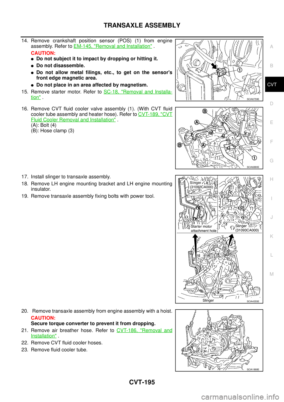
14. Remove crankshaft position sensor (POS) (1) from engine
assembly. Refer to EM-145, "
Removal and Installation" .
CAUTION:
�Do not subject it to impact by dropping or hitting it.
�Do not disassemble.
�Do not allow metal filings, etc., to get on the sensor's
front edge magnetic area.
�Do not place in an area affected by magnetism.
15. Remove starter motor. Refer to SC-18, "
Removal and Installa-
tion" .
16. Remove CVT fluid cooler valve assembly (1). (With CVT fluid
cooler tube assembly and heater hose). Refer to CVT-189, "
CVT
Fluid Cooler Removal and Installation" .
(A): Bolt (4)
(B): Hose clamp (3)
17. Install slinger to transaxle assembly.
18. Remove LH engine mounting bracket and LH engine mounting
insulator.
19. Remove transaxle assembly fixing bolts with power tool.
20. Remove transaxle assembly from engine assembly with a hoist.
CAUTION:
Secure torque converter to prevent it from dropping.
21. Remove air breather hose. Refer to CVT-186, "
Removal and
Installation" .
22. Remove CVT fluid cooler hoses.
23. Remove fluid cooler tube.
SCIA6759E
SCIA6880E
SCIA4355E
SCIA1868E
Page 1203 of 3502
TRANSAXLE ASSEMBLY
CVT-197
D
E
F
G
H
I
J
K
L
MA
B
CVT
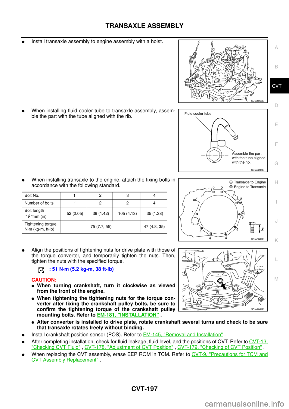
�Install transaxle assembly to engine assembly with a hoist.
�When installing fluid cooler tube to transaxle assembly, assem-
ble the part with the tube aligned with the rib.
�When installing transaxle to the engine, attach the fixing bolts in
accordance with the following standard.
�Align the positions of tightening nuts for drive plate with those of
the torque converter, and temporarily tighten the nuts. Then,
tighten the nuts with the specified torque.
CAUTION:
�When turning crankshaft, turn it clockwise as viewed
from the front of the engine.
�When tightening the tightening nuts for the torque con-
verter after fixing the crankshaft pulley bolts, be sure to
confirm the tightening torque of the crankshaft pulley
mounting bolts. Refer to EM-181, "
INSTALLATION" .
�After converter is installed to drive plate, rotate crankshaft several turns and check to be sure
that transaxle rotates freely without binding.
�Install crankshaft position sensor (POS). Refer to EM-145, "Removal and Installation" .
�After completing installation, check for fluid leakage, fluid level, and the positions of CVT. Refer to CVT-13,
"Checking CVT Fluid" , CVT-178, "Adjustment of CVT Position" , CVT-179, "Checking of CVT Position" .
�When replacing the CVT assembly, erase EEP ROM in TCM. Refer to CVT-9, "Precautions for TCM and
CVT Assembly Replacement" .
SCIA1868E
SCIA2285E
Bolt No. 1 2 3 4
Number of bolts 1 2 2 4
Bolt length
“ ”mm (in) 52 (2.05) 36 (1.42) 105 (4.13) 35 (1.38)
Tightening torque
N·m (kg-m, ft-lb)75 (7.7, 55) 47 (4.8, 35)
SCIA6882E
: 51 N·m (5.2 kg-m, 38 ft-lb)
SCIA1861E