Page 2426 of 3502
FL-10
FUEL TANK
�After removing/installing rear suspension assembly, make sure to adjust wheel alignment and then, adjust
neutral position of steering angle sensor. Refer to RSU-5, "
Wheel Alignment Inspection" and BRC-40,
"Adjustment of Steering Angle Sensor Neutral Position" .
Page 2429 of 3502

FSU-1
FRONT SUSPENSION
E SUSPENSION
CONTENTS
C
D
F
G
H
I
J
K
L
M
SECTION FSU
A
B
FSU
FRONT SUSPENSION
PRECAUTIONS .......................................................... 2
Caution ..................................................................... 2
PREPARATION ........................................................... 3
Special Service Tools ............................................... 3
Commercial Service Tools ........................................ 3
NOISE, VIBRATION AND HARSHNESS (NVH)
TROUBLESHOOTING ................................................ 4
NVH Troubleshooting Chart ..................................... 4
FRONT SUSPENSION ASSEMBLY ........................... 5
On-Vehicle Inspection .............................................. 5
INSPECTION OF TRANSVERSE LINK BALL
JOINT END PLAY ................................................. 5
STRUT INSPECTION ........................................... 5
Wheel Alignment Inspection ..................................... 5
DESCRIPTION ...................................................... 5
PRELIMINARY CHECK ........................................ 5
INSPECTION OF CAMBER, CASTER AND
KINGPIN INCLINATION ANGLES. ....................... 5
Components ............................................................. 7
Removal and Installation .......................................... 8
REMOVAL ............................................................. 8
INSTALLATION ..................................................... 9
COIL SPRING AND STRUT ..................................... 10
Removal and Installation ........................................ 10
REMOVAL ........................................................... 10INSTALLATION ................................................... 11
Disassembly and Assembly .................................... 11
DISASSEMBLY ................................................... 11
INSPECTION AFTER DISASSEMBLY ................ 12
ASSEMBLY ......................................................... 12
TRANSVERSE LINK ................................................. 14
Removal and Installation ........................................ 14
REMOVAL ........................................................... 14
INSPECTION AFTER REMOVAL ....................... 14
INSTALLATION ................................................... 15
STABILIZER BAR ..................................................... 16
Removal and Installation ........................................ 16
REMOVAL ........................................................... 16
INSPECTION AFTER REMOVAL ....................... 16
INSTALLATION ................................................... 16
FRONT SUSPENSION MEMBER ............................. 17
Removal and Installation ........................................ 17
REMOVAL ........................................................... 17
INSPECTION AFTER REMOVAL ....................... 17
INSTALLATION ................................................... 17
SERVICE DATA AND SPECIFICATIONS (SDS) ...... 18
Wheel Alignment (Unladen*) .................................. 18
Ball Joint ................................................................. 18
Wheelarch Height (Unladen*) ................................. 18
Page 2430 of 3502
FSU-2
PRECAUTIONS
PRECAUTIONSPFP:00001
CautionBES0003G
�When installing rubber bushings, final tightening must be performed under unladen conditions with tires
on ground. Oil will shorten the life of rubber bushings. Be sure to wipe off any spilled oil.
–Unladen conditions mean that fuel, engine coolant and lubricant are full. A spare tire, a jack, hand tools
and mats are in designated positions.
�After servicing suspension parts, be sure to check wheel alignment.
�Self-lock nut are not reusable. Always use new ones when installing. Since new self-lock nuts are pre-
oiled, tighten as they are.
Page 2432 of 3502
FSU-4
NOISE, VIBRATION AND HARSHNESS (NVH) TROUBLESHOOTING
NOISE, VIBRATION AND HARSHNESS (NVH) TROUBLESHOOTINGPFP:00003
NVH Troubleshooting ChartBES0003J
Use chart below to help you find the cause of the symptom. If necessary, repair or replace these parts.
×: ApplicableReference page
FSU-7FSU-12
—
—
—
FSU-7FSU-5FSU-16
NVH in FAX and FSU section
NVH in WT section
NVH in FAX section
NVH in BR section
NVH in PS section
Possible cause and Suspected parts
Improper installation, looseness
Strut deformation, damage or deflection
Bushing or mounting deterioration
Parts interference
Spring fatigue
Suspension looseness
Incorrect wheel alignment
Stabilizer bar fatigue
FRONT AXLE AND FRONT SUSPENSION
ROAD WHEELS
DRIVE SHAFT
BRAKES
STEERING
Symptom Front suspensionNoise×××××× ×××××
Shake×××× × ×××××
Vibration××××× × × ×
Shimmy×××× ×××××
Judder××× ×× × ×
Poor quality ride or handling××××× ××××
Page 2433 of 3502

FRONT SUSPENSION ASSEMBLY
FSU-5
C
D
F
G
H
I
J
K
L
MA
B
FSU
FRONT SUSPENSION ASSEMBLYPFP:54010
On-Vehicle Inspection BES0003K
Make sure that the mounting conditions (looseness, back lash) of each component and component status
(wear, damage) are normal.
INSPECTION OF TRANSVERSE LINK BALL JOINT END PLAY
1. Set front wheels in a straight-ahead position. Do not depress brake pedal.
2. Measure axial end play by placing an iron pry bar or a similar item between suspension arm and strut
assembly and prying up and down.
CAUTION:
Be careful not to damage ball joint boot. Do not damage the installation position by applying
excessive force.
STRUT INSPECTION
Check for oil leakage, damage, and breakage of installation positions.
Wheel Alignment InspectionBES0003L
DESCRIPTION
Measure wheel alignment under unladen conditions.
NOTE:
“Unladen” conditions mean that fuel, engine coolant, and lubricant are full. A spare tire, a jack, hand tools and
mats are in designated positions.
PRELIMINARY CHECK
1. Check Tires for improper air pressure and wear.
2. Check Road wheels for runout. Refer to WT-3, "
ROAD WHEEL" .
3. Check Wheel bearing axial end play. Refer to FAX-5, "
WHEEL BEARING INSPECTION" .
4. Check Transverse link ball joint axial end play. Refer to FSU-14, "
INSPECTION AFTER REMOVAL" .
5. Check Strut operation.
6. Check Each mounting point of axle and suspension for looseness and deformation.
7. Check Each link, rod, and member for cracks, deformation and other damage.
8. Check Vehicle height (posture).
INSPECTION OF CAMBER, CASTER AND KINGPIN INCLINATION ANGLES.
�Camber, caster, kingpin inclination angles cannot be adjusted.
�Before inspection, mount wheels onto turning radius gauge. Mount rear wheels onto a stand that has
same height so vehicle will remain horizontal.
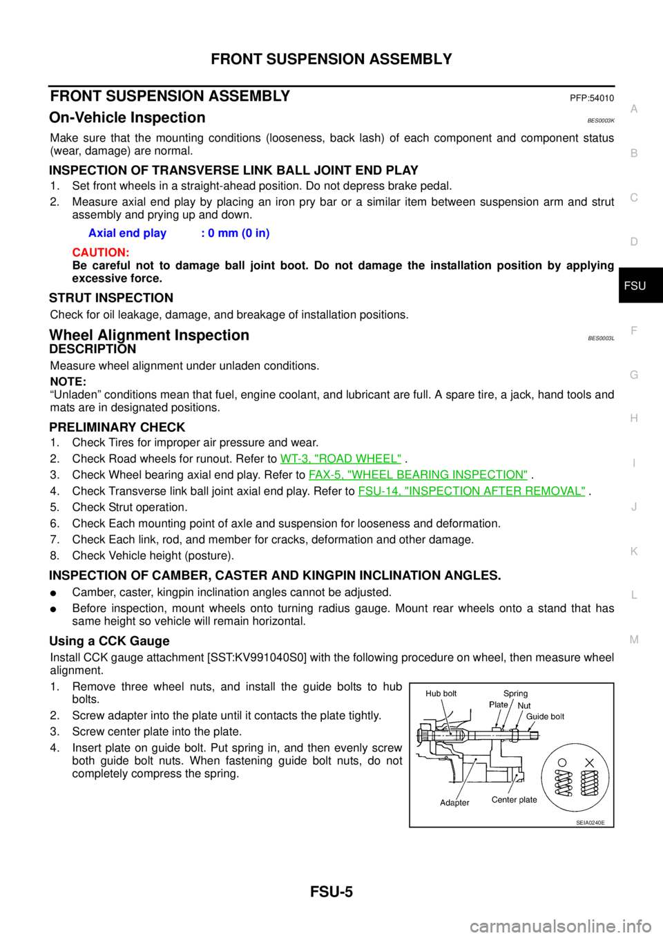
Using a CCK Gauge
Install CCK gauge attachment [SST:KV991040S0] with the following procedure on wheel, then measure wheel
alignment.
1. Remove three wheel nuts, and install the guide bolts to hub
bolts.
2. Screw adapter into the plate until it contacts the plate tightly.
3. Screw center plate into the plate.
4. Insert plate on guide bolt. Put spring in, and then evenly screw
both guide bolt nuts. When fastening guide bolt nuts, do not
completely compress the spring.Axial end play : 0 mm (0 in)
SEIA0240E
Page 2434 of 3502

FSU-6
FRONT SUSPENSION ASSEMBLY
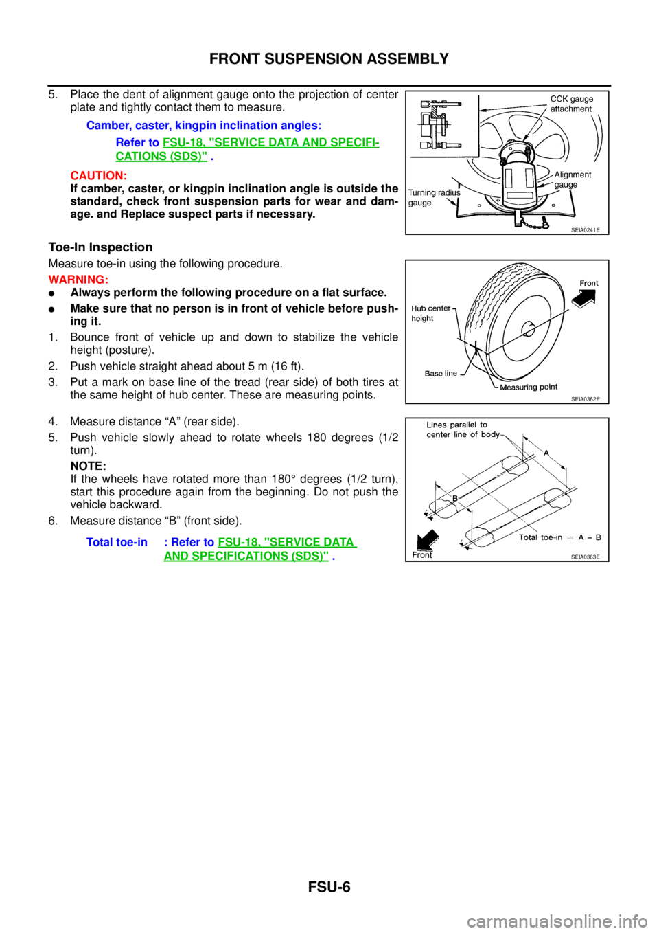
5. Place the dent of alignment gauge onto the projection of center
plate and tightly contact them to measure.
CAUTION:
If camber, caster, or kingpin inclination angle is outside the
standard, check front suspension parts for wear and dam-
age. and Replace suspect parts if necessary.
Toe-In Inspection
Measure toe-in using the following procedure.
WARNING:
�Always perform the following procedure on a flat surface.
�Make sure that no person is in front of vehicle before push-
ing it.
1. Bounce front of vehicle up and down to stabilize the vehicle
height (posture).
2. Push vehicle straight ahead about 5 m (16 ft).
3. Put a mark on base line of the tread (rear side) of both tires at
the same height of hub center. These are measuring points.
4. Measure distance “A” (rear side).
5. Push vehicle slowly ahead to rotate wheels 180 degrees (1/2
turn).
NOTE:
If the wheels have rotated more than 180° degrees (1/2 turn),
start this procedure again from the beginning. Do not push the
vehicle backward.
6. Measure distance “B” (front side).Camber, caster, kingpin inclination angles:
Refer to FSU-18, "
SERVICE DATA AND SPECIFI-
CATIONS (SDS)" .
SEIA0241E
SEIA0362E
Total toe-in : Refer to FSU-18, "SERVICE DATA
AND SPECIFICATIONS (SDS)" .SEIA0363E
Page 2435 of 3502
FRONT SUSPENSION ASSEMBLY
FSU-7
C
D
F
G
H
I
J
K
L
MA
B
FSU
ComponentsBES0003M
PEIA0100E
Page 2436 of 3502

FSU-8
FRONT SUSPENSION ASSEMBLY
Removal and Installation BES0003N
REMOVAL
1. Remove cowl top panel and hood. Install engine slinger, and then hoist engine. (VQ35DE models) Refer
to EI-21, "
COWL TOP" , BL-13, "HOOD" .
2. Remove tires from vehicle.
3. Remove wheel sensor from steering knuckle. Refer to BRC-33, "
WHEEL SENSORS" .
CAUTION:
Do not pull on wheel sensor harness.
4. Remove torque member fixing bolts. Hang torque member in a place where it will not interfere with work.
Refer to BR-26, "
FRONT DISC BRAKE" .
NOTE:
Do not depress brake pedal while brake caliper is removed.
5. Remove undercover and splash guard.
6. Remove disc rotor. Refer to FA X - 5 , "
Removal and Installation" .
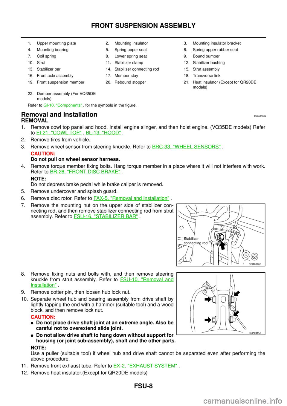
7. Remove the mounting nut on the upper side of stabilizer con-
necting rod, and then remove stabilizer connecting rod from strut
assembly. Refer to FSU-16, "
STABILIZER BAR" .
8. Remove fixing nuts and bolts with, and then remove steering
knuckle from strut assembly. Refer to FSU-10, "
Removal and
Installation" .
9. Remove cotter pin, then loosen hub lock nut.
10. Separate wheel hub and bearing assembly from drive shaft by
lightly tapping the end with a hammer (suitable tool) and a wood
block, and then remove lock nut.
CAUTION:
�Do not place drive shaft joint at an extreme angle. Also be
careful not to overextend slide joint.
�Do not allow drive shaft to hang down without support for
housing (or joint sub-assembly), shaft and the other parts.
NOTE:
Use a puller (suitable tool) if wheel hub and drive shaft cannot be separated even after performing the
above procedure.
11. Remove front exhaust tube. Refer to EX-2, "
EXHAUST SYSTEM" .
12. Remove heat insulator.(Except for QR20DE models)
1. Upper mounting plate 2. Mounting insulator 3. Mounting insulator bracket
4. Mounting bearing 5. Spring upper seat 6. Spring upper rubber seat
7. Coil spring 8. Lower spring seat 9. Bound bumper
10. Strut 11. Stabilizer clamp 12. Stabilizer bushing
13. Stabilizer bar 14. Stabilizer connecting rod 15. Strut assembly
16. Front axle assembly 17. Member stay 18. Transverse link
19. Front suspension member 20. Rebound stopper 21. Heat insulator (Except for QR20DE
models)
22. Damper assembly (For VQ35DE
models)
Refer to GI-10, "
Components" , for the symbols in the figure.
SEIA0370E
SEIA0411J