Page 3208 of 3502

RSU-16
STABILIZER BAR
STABILIZER BARPFP:54611
Removal and InstallationBES0004A
REMOVAL
1. Remove tires from vehicle.
2. Remove mounting nut on lower side of connecting rod.
3. If necessary remove mounting nut on upper side of connecting rod. Remove connecting rod from mount-
ing bracket of suspension arm.
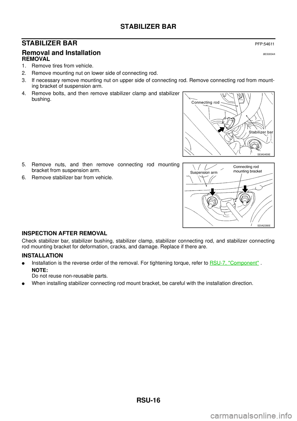
4. Remove bolts, and then remove stabilizer clamp and stabilizer
bushing.
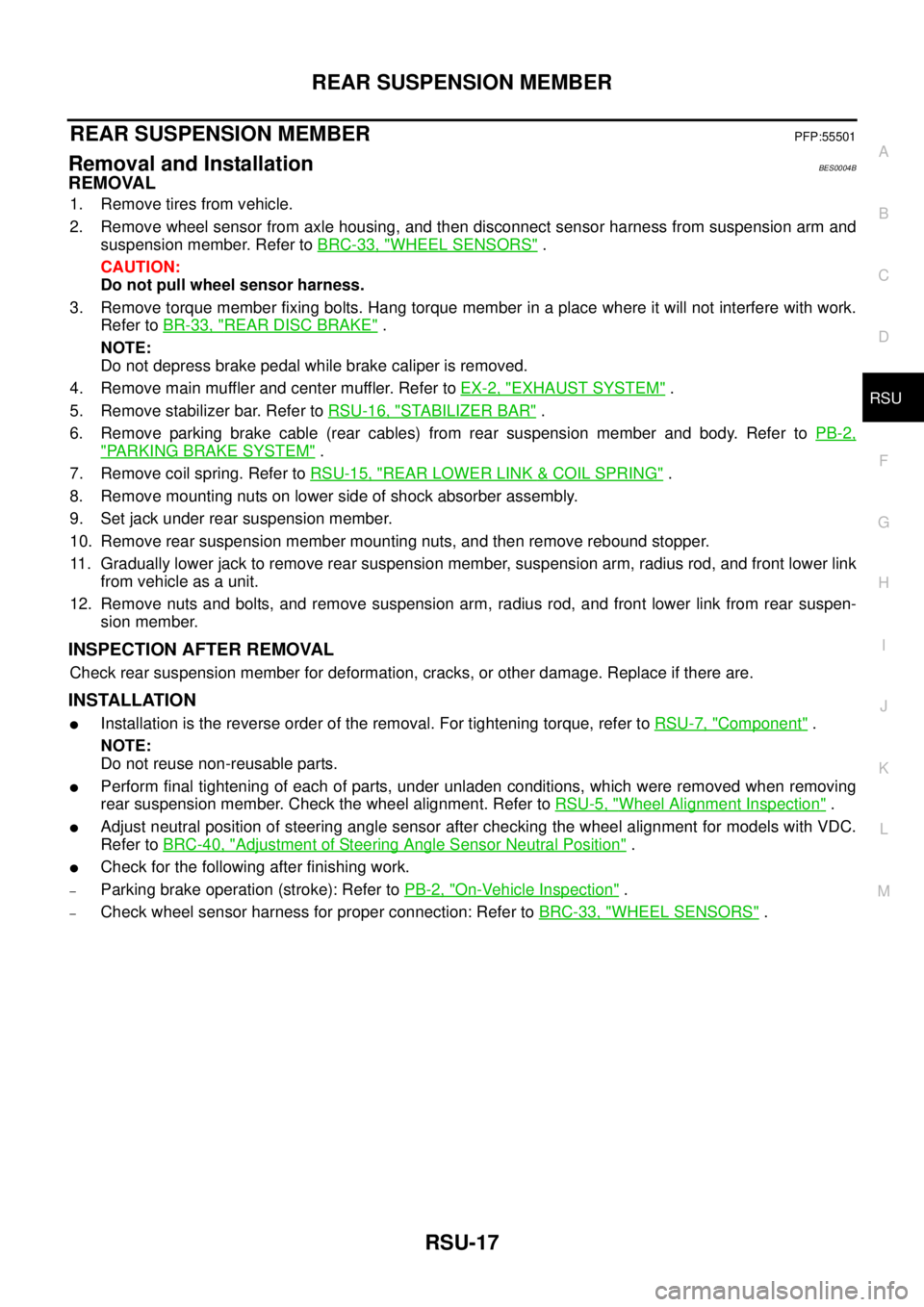
5. Remove nuts, and then remove connecting rod mounting
bracket from suspension arm.
6. Remove stabilizer bar from vehicle.
INSPECTION AFTER REMOVAL
Check stabilizer bar, stabilizer bushing, stabilizer clamp, stabilizer connecting rod, and stabilizer connecting
rod mounting bracket for deformation, cracks, and damage. Replace if there are.
INSTALLATION
�Installation is the reverse order of the removal. For tightening torque, refer to RSU-7, "Component" .
NOTE:
Do not reuse non-reusable parts.
�When installing stabilizer connecting rod mount bracket, be careful with the installation direction.
SEIA0459E
SDIA2280E
Page 3209 of 3502

REAR SUSPENSION MEMBER
RSU-17
C
D
F
G
H
I
J
K
L
MA
B
RSU
REAR SUSPENSION MEMBERPFP:55501
Removal and InstallationBES0004B
REMOVAL
1. Remove tires from vehicle.
2. Remove wheel sensor from axle housing, and then disconnect sensor harness from suspension arm and
suspension member. Refer to BRC-33, "
WHEEL SENSORS" .
CAUTION:
Do not pull wheel sensor harness.
3. Remove torque member fixing bolts. Hang torque member in a place where it will not interfere with work.
Refer to BR-33, "
REAR DISC BRAKE" .
NOTE:
Do not depress brake pedal while brake caliper is removed.
4. Remove main muffler and center muffler. Refer to EX-2, "
EXHAUST SYSTEM" .
5. Remove stabilizer bar. Refer to RSU-16, "
STABILIZER BAR" .
6. Remove parking brake cable (rear cables) from rear suspension member and body. Refer to PB-2,
"PARKING BRAKE SYSTEM" .
7. Remove coil spring. Refer to RSU-15, "
REAR LOWER LINK & COIL SPRING" .
8. Remove mounting nuts on lower side of shock absorber assembly.
9. Set jack under rear suspension member.
10. Remove rear suspension member mounting nuts, and then remove rebound stopper.
11. Gradually lower jack to remove rear suspension member, suspension arm, radius rod, and front lower link
from vehicle as a unit.
12. Remove nuts and bolts, and remove suspension arm, radius rod, and front lower link from rear suspen-
sion member.
INSPECTION AFTER REMOVAL
Check rear suspension member for deformation, cracks, or other damage. Replace if there are.
INSTALLATION
�Installation is the reverse order of the removal. For tightening torque, refer to RSU-7, "Component" .
NOTE:
Do not reuse non-reusable parts.
�Perform final tightening of each of parts, under unladen conditions, which were removed when removing
rear suspension member. Check the wheel alignment. Refer to RSU-5, "
Wheel Alignment Inspection" .
�Adjust neutral position of steering angle sensor after checking the wheel alignment for models with VDC.
Refer to BRC-40, "
Adjustment of Steering Angle Sensor Neutral Position" .
�Check for the following after finishing work.
–Parking brake operation (stroke): Refer to PB-2, "On-Vehicle Inspection" .
–Check wheel sensor harness for proper connection: Refer to BRC-33, "WHEEL SENSORS" .
Page 3433 of 3502

WT-1
ROAD WHEELS & TYRES
E SUSPENSION
CONTENTS
C
D
F
G
H
I
J
K
L
M
SECTION WT
A
B
WT
ROAD WHEELS & TYRES
NOISE, VIBRATION AND HARSHNESS (NVH)
TROUBLESHOOTING ................................................ 2
NVH Troubleshooting Chart ..................................... 2
ROAD WHEEL ............................................................ 3
Inspection ................................................................. 3
ALUMINUM WHEEL ............................................. 3
STEEL WHEEL ..................................................... 3
ROAD WHEEL AND TYRE ASSEMBLY .................... 4Balancing Wheels (Bonding Weight Type) ............... 4
REMOVAL ............................................................. 4
WHEEL BALANCE ADJUSTMENT ....................... 4
Rotation .................................................................... 5
SERVICE DATA AND SPECIFICATIONS (SDS) ........ 6
Road Wheel .............................................................. 6
Tyre ........................................................................... 6
Page 3434 of 3502

WT-2
NOISE, VIBRATION AND HARSHNESS (NVH) TROUBLESHOOTING
NOISE, VIBRATION AND HARSHNESS (NVH) TROUBLESHOOTINGPFP:00003
NVH Troubleshooting ChartBES0004G
Use chart below to help you find the cause of the symptom. If necessary, repair or replace these parts.
×: ApplicableReference page
FAX-5
, RAX-3WT-3
WT-4
WT-6WT-6—
—
WT-6
NVH in FAX and FSU sections.
NVH in RAX and RSU sections.
Refer to TYRES in this chart.
Refer to ROAD WHEEL in this chart.
NVH in FAX, RAX section.
NVH in BR section.
NVH in PS section.
Possible cause and SUSPECTED PARTS
Improper installation, looseness
Out-of-round
Imbalance
Incorrect tyre pressure
Uneven tyre wear
Deformation or damage
Non-uniformity
Incorrect tyre size
FRONT AXLE AND FRONT SUSPENSION
REAR AXLE AND REAR SUSPENSION
TYRES
ROAD WHEELS
DRIVE SHAFT
BRAKE
STEERING
SymptomTYRESNoise××××××× ×× ××××
Shake×××××× ××× ××××
Vibration× ××× × ×
Shimmy×××××××××× × ××
Judder×××××× ××× × ××
Poor quality ride
or handling×××××× ××× ×
ROAD WHEELNoise××× × ××× ×××
Shake××× × ××× ×××
Shimmy, judder××× × ××× ××
Poor quality ride
or handling××× × ×××