Page 3179 of 3502
SUNROOF
RF-15
C
D
E
F
G
H
J
K
L
MA
B
RF
Work FlowBIS0010W
1. Check the symptom and customer's requests.
2. Understand the outline of system. Refer to RF-11, "
System Description" .
3. According to the trouble diagnosis chart, repair or replace the cause of the malfunction. Refer to RF-15,
"Trouble Diagnosis Chart by Symptom" .
4. Does sunroof system operate normally? If Yes, GO TO 5. If No, GO TO 3.
5. INSPECTION END.
Trouble Diagnosis Chart by SymptomBIS0010X
Check BCM Power Supply and Ground CircuitBIS0010Y
1. CHECK FUSE
�Check 10A fuse [No.1, located in fuse block (J/B)]
�Check 15A fuse [No.17, located in fuse block (J/B)]
�Check 50A fusible link (letter M located in the fuse and fusible link box).
NOTE:
Refer to RF-10, "
Component Parts and Harness Connector Location" .
OK or NG
OK >> GO TO 2.
NG >> If fuse is blown out, be sure to eliminate cause of malfunction before installing new fuse. Refer to
PG-3, "
POWER SUPPLY ROUTING CIRCUIT" .
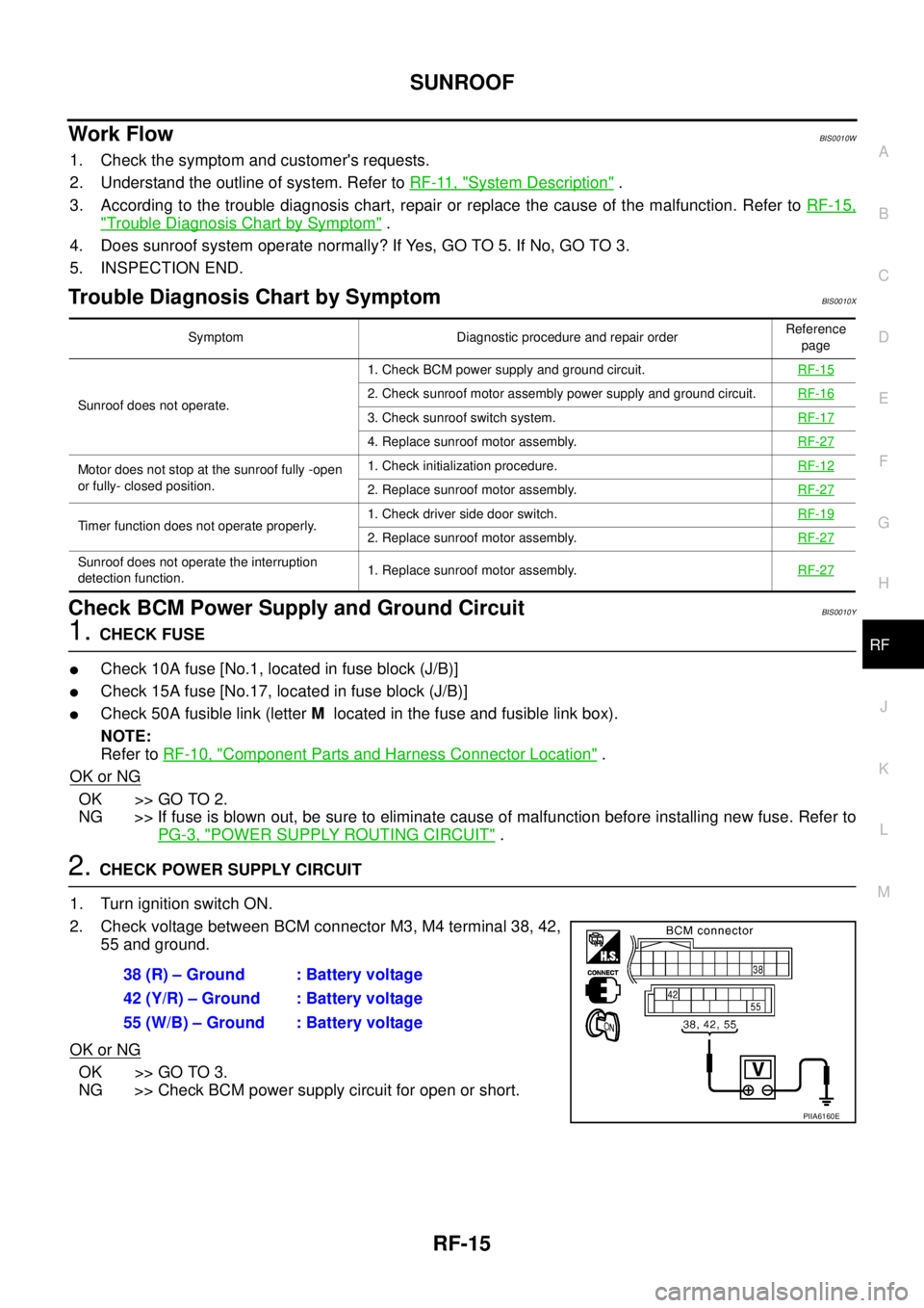
2. CHECK POWER SUPPLY CIRCUIT
1. Turn ignition switch ON.
2. Check voltage between BCM connector M3, M4 terminal 38, 42,
55 and ground.
OK or NG
OK >> GO TO 3.
NG >> Check BCM power supply circuit for open or short.
Symptom Diagnostic procedure and repair orderReference
page
Sunroof does not operate.1. Check BCM power supply and ground circuit.RF-15
2. Check sunroof motor assembly power supply and ground circuit.RF-16
3. Check sunroof switch system.RF-17
4. Replace sunroof motor assembly.RF-27
Motor does not stop at the sunroof fully -open
or fully- closed position.1. Check initialization procedure.RF-12
2. Replace sunroof motor assembly.RF-27
Timer function does not operate properly.1. Check driver side door switch.RF-192. Replace sunroof motor assembly.RF-27
Sunroof does not operate the interruption
detection function.1. Replace sunroof motor assembly.RF-27
38 (R) – Ground : Battery voltage
42 (Y/R) – Ground : Battery voltage
55 (W/B) – Ground : Battery voltage
PIIA6160E
Page 3180 of 3502
RF-16
SUNROOF
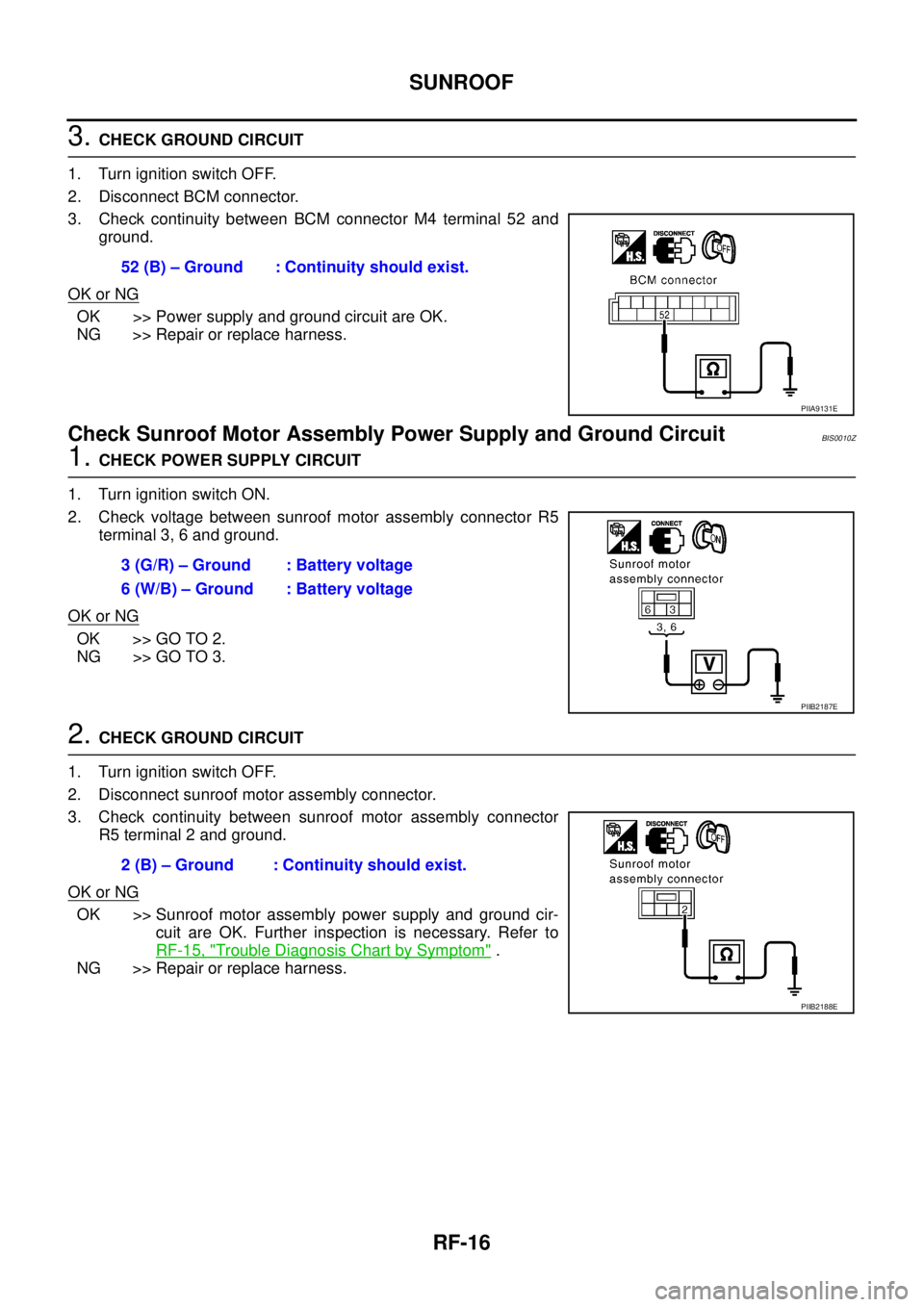
3. CHECK GROUND CIRCUIT
1. Turn ignition switch OFF.
2. Disconnect BCM connector.
3. Check continuity between BCM connector M4 terminal 52 and
ground.
OK or NG
OK >> Power supply and ground circuit are OK.
NG >> Repair or replace harness.
Check Sunroof Motor Assembly Power Supply and Ground CircuitBIS0010Z
1. CHECK POWER SUPPLY CIRCUIT
1. Turn ignition switch ON.
2. Check voltage between sunroof motor assembly connector R5
terminal 3, 6 and ground.
OK or NG
OK >> GO TO 2.
NG >> GO TO 3.
2. CHECK GROUND CIRCUIT
1. Turn ignition switch OFF.
2. Disconnect sunroof motor assembly connector.
3. Check continuity between sunroof motor assembly connector
R5 terminal 2 and ground.
OK or NG
OK >> Sunroof motor assembly power supply and ground cir-
cuit are OK. Further inspection is necessary. Refer to
RF-15, "
Trouble Diagnosis Chart by Symptom" .
NG >> Repair or replace harness.52 (B) – Ground : Continuity should exist.
PIIA9131E
3 (G/R) – Ground : Battery voltage
6 (W/B) – Ground : Battery voltage
PIIB2187E
2 (B) – Ground : Continuity should exist.
PIIB2188E
Page 3181 of 3502
SUNROOF
RF-17
C
D
E
F
G
H
J
K
L
MA
B
RF
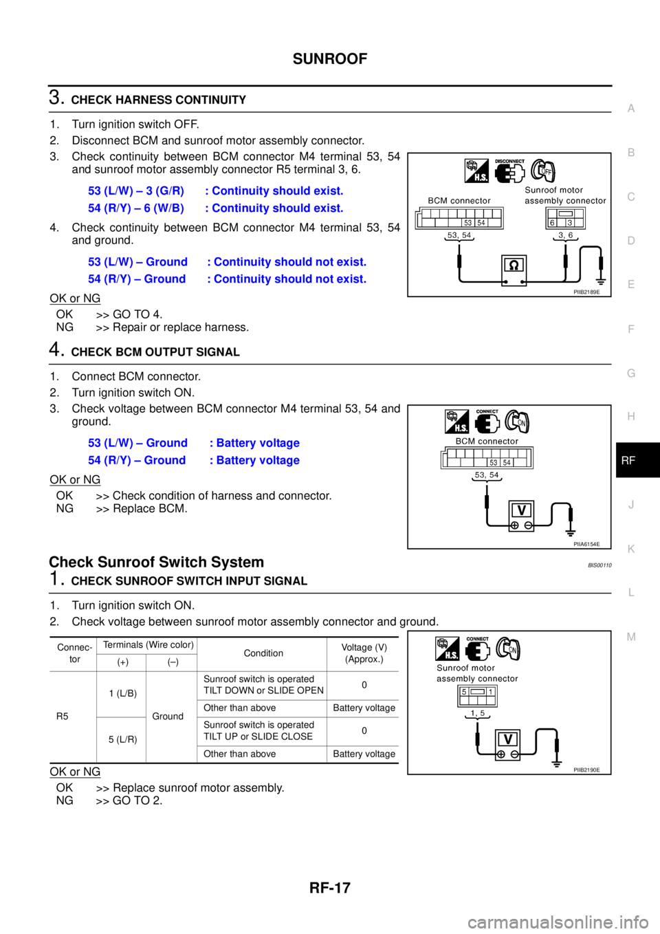
3. CHECK HARNESS CONTINUITY
1. Turn ignition switch OFF.
2. Disconnect BCM and sunroof motor assembly connector.
3. Check continuity between BCM connector M4 terminal 53, 54
and sunroof motor assembly connector R5 terminal 3, 6.
4. Check continuity between BCM connector M4 terminal 53, 54
and ground.
OK or NG
OK >> GO TO 4.
NG >> Repair or replace harness.
4. CHECK BCM OUTPUT SIGNAL
1. Connect BCM connector.
2. Turn ignition switch ON.
3. Check voltage between BCM connector M4 terminal 53, 54 and
ground.
OK or NG
OK >> Check condition of harness and connector.
NG >> Replace BCM.
Check Sunroof Switch SystemBIS00110
1. CHECK SUNROOF SWITCH INPUT SIGNAL
1. Turn ignition switch ON.
2. Check voltage between sunroof motor assembly connector and ground.
OK or NG
OK >> Replace sunroof motor assembly.
NG >> GO TO 2.53 (L/W) – 3 (G/R) : Continuity should exist.
54 (R/Y) – 6 (W/B) : Continuity should exist.
53 (L/W) – Ground : Continuity should not exist.
54 (R/Y) – Ground : Continuity should not exist.
PIIB2189E
53 (L/W) – Ground : Battery voltage
54 (R/Y) – Ground : Battery voltage
PIIA6154E
Connec-
torTerminals (Wire color)
ConditionVoltage (V)
(Approx.)
(+) (–)
R51 (L/B)
GroundSunroof switch is operated
TILT DOWN or SLIDE OPEN0
Other than above Battery voltage
5 (L/R)Sunroof switch is operated
TILT UP or SLIDE CLOSE0
Other than above Battery voltage
PIIB2190E
Page 3182 of 3502
RF-18
SUNROOF
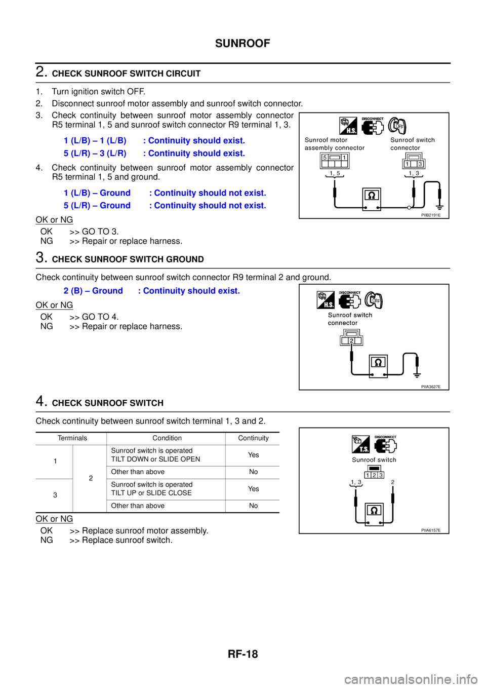
2. CHECK SUNROOF SWITCH CIRCUIT
1. Turn ignition switch OFF.
2. Disconnect sunroof motor assembly and sunroof switch connector.
3. Check continuity between sunroof motor assembly connector
R5 terminal 1, 5 and sunroof switch connector R9 terminal 1, 3.
4. Check continuity between sunroof motor assembly connector
R5 terminal 1, 5 and ground.
OK or NG
OK >> GO TO 3.
NG >> Repair or replace harness.
3. CHECK SUNROOF SWITCH GROUND
Check continuity between sunroof switch connector R9 terminal 2 and ground.
OK or NG
OK >> GO TO 4.
NG >> Repair or replace harness.
4. CHECK SUNROOF SWITCH
Check continuity between sunroof switch terminal 1, 3 and 2.
OK or NG
OK >> Replace sunroof motor assembly.
NG >> Replace sunroof switch.1 (L/B) – 1 (L/B) : Continuity should exist.
5 (L/R) – 3 (L/R) : Continuity should exist.
1 (L/B) – Ground : Continuity should not exist.
5 (L/R) – Ground : Continuity should not exist.
PIIB2191E
2 (B) – Ground : Continuity should exist.
PIIA3627E
Terminals Condition Continuity
1
2Sunroof switch is operated
TILT DOWN or SLIDE OPENYe s
Other than above No
3Sunroof switch is operated
TILT UP or SLIDE CLOSEYe s
Other than above No
PIIA6157E
Page 3183 of 3502

SUNROOF
RF-19
C
D
E
F
G
H
J
K
L
MA
B
RF
Check Driver Side Door Switch BIS00111
1. CHECK DOOR SWITCH INPUT SIGNAL
With CONSULT-II
Check “DOOR SW-DR” in “DATA MONITOR” mode with CONSULT-II. Refer to BL-30, "
Data Monitor"
Without CONSULT-II
Check voltage between BCM connector and ground.
OK or NG
OK >> Driver side door switch circuit is OK.
NG >> GO TO 2.
2. CHECK HARNESS CONTINUITY
1. Turn ignition switch OFF.
2. Disconnect driver side door switch and BCM connector.
3. Check continuity between BCM connector M5 terminal 62 and
driver side door switch connector B10 terminal 2.
4. Check continuity between BCM connector M5 terminal 62 and
ground.
OK or NG
OK >> GO TO 3.
NG >> Repair or replace harness.
Monitor item Condition
DOOR SW-DROPEN : ON
CLOSE : OFF
PIIA2464E
ConnectorTerminals (Wire color)
Condition of
driver side doorVoltage (V)
(Approx.)
(+) (–)
M5 62 (SB) GroundOPEN 0
CLOSE Battery voltage
PIIA9880E
62 (SB) – 2 (SB) : Continuity should exist.
62 (SB) – Ground : Continuity should not exist.
PIIB1225E
Page 3184 of 3502
RF-20
SUNROOF
3. CHECK DOOR SWITCH
Check continuity between driver side door switch terminal 2 and
ground part of door switch.
OK or NG
OK >> GO TO 4.
NG >> Replace driver side door switch.
4. CHECK BCM OUTPUT SIGNAL
1. Connect BCM connector.
2. Check voltage between BCM connector M5 terminal 62 and
ground.
OK or NG
OK >> Check condition of connection of each connector.
NG >> Replace BCM.
TerminalCondition of
driver side door switchContinuity
2Ground part of driver
side door switchPushed No
Released Yes
PIIB1223E
62 (SB) – Ground : Battery voltage
PIIA9880E
Page 3185 of 3502
SUNROOF
RF-21
C
D
E
F
G
H
J
K
L
MA
B
RF
Wind Deflector InspectionBIS00112
Make sure the wind deflector is properly function by manual. If a mal-
function is detected, remove and visually check it. If it is damaged,
replace it with a new one. If no damage is found, reinstall it properly.
Link and Wire AssemblyBIS00113
NOTE:
Before replacing a suspect part, carefully inspect if it is the source of noise being experienced.
1. Check link if coating film has peeled off and substrate is visible. Check also if link is the source of noise. If
it is, replace it.
2. Visually check if a sufficient amount of grease has been applied to wire and rail groove. If not, add grease
as required.
3. Check wire for any damage or deterioration. If any damage is found, replace wire.
Fitting AdjustmentBIS00114
PIIA5061E
PIIA9882E
Page 3186 of 3502
RF-22
SUNROOF
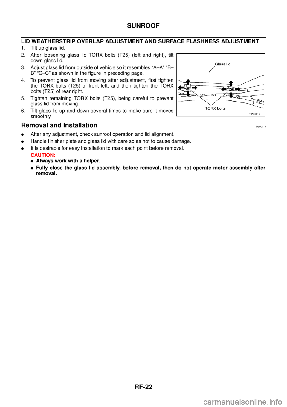
LID WEATHERSTRIP OVERLAP ADJUSTMENT AND SURFACE FLASHNESS ADJUSTMENT
1. Tilt up glass lid.
2. After loosening glass lid TORX bolts (T25) (left and right), tilt
down glass lid.
3. Adjust glass lid from outside of vehicle so it resembles “A–A” “B–
B” “C–C” as shown in the figure in preceding page.
4. To prevent glass lid from moving after adjustment, first tighten
the TORX bolts (T25) of front left, and then tighten the TORX
bolts (T25) of rear right.
5. Tighten remaining TORX bolts (T25), being careful to prevent
glass lid from moving.
6. Tilt glass lid up and down several times to make sure it moves
smoothly.
Removal and InstallationBIS00115
�After any adjustment, check sunroof operation and lid alignment.
�Handle finisher plate and glass lid with care so as not to cause damage.
�It is desirable for easy installation to mark each point before removal.
CAUTION:
�Always work with a helper.
�Fully close the glass lid assembly, before removal, then do not operate motor assembly after
removal.
PIIA3501E