Page 2725 of 3502
HEADLAMP - XENON TYPE -
LT-37
C
D
E
F
G
H
I
J
L
MA
B
LT
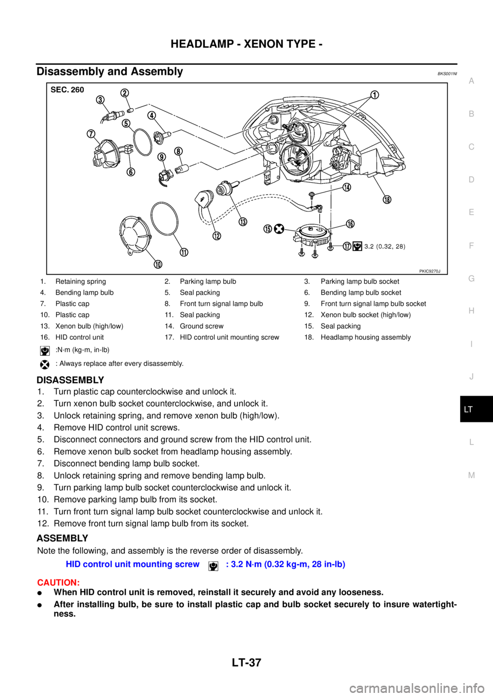
Disassembly and AssemblyBKS001NI
DISASSEMBLY
1. Turn plastic cap counterclockwise and unlock it.
2. Turn xenon bulb socket counterclockwise, and unlock it.
3. Unlock retaining spring, and remove xenon bulb (high/low).
4. Remove HID control unit screws.
5. Disconnect connectors and ground screw from the HID control unit.
6. Remove xenon bulb socket from headlamp housing assembly.
7. Disconnect bending lamp bulb socket.
8. Unlock retaining spring and remove bending lamp bulb.
9. Turn parking lamp bulb socket counterclockwise and unlock it.
10. Remove parking lamp bulb from its socket.
11. Turn front turn signal lamp bulb socket counterclockwise and unlock it.
12. Remove front turn signal lamp bulb from its socket.
ASSEMBLY
Note the following, and assembly is the reverse order of disassembly.
CAUTION:
�When HID control unit is removed, reinstall it securely and avoid any looseness.
�After installing bulb, be sure to install plastic cap and bulb socket securely to insure watertight-
ness.
1. Retaining spring 2. Parking lamp bulb 3. Parking lamp bulb socket
4. Bending lamp bulb 5. Seal packing 6. Bending lamp bulb socket
7. Plastic cap 8. Front turn signal lamp bulb 9. Front turn signal lamp bulb socket
10. Plastic cap 11. Seal packing 12. Xenon bulb socket (high/low)
13. Xenon bulb (high/low) 14. Ground screw 15. Seal packing
16. HID control unit 17. HID control unit mounting screw 18. Headlamp housing assembly
:N·m (kg-m, in-lb)
: Always replace after every disassembly.
PKIC9270J
HID control unit mounting screw : 3.2 N·m (0.32 kg-m, 28 in-lb)
Page 2726 of 3502
LT-38
HEADLAMP - HALOGEN TYPE -
HEADLAMP - HALOGEN TYPE -PFP:26010
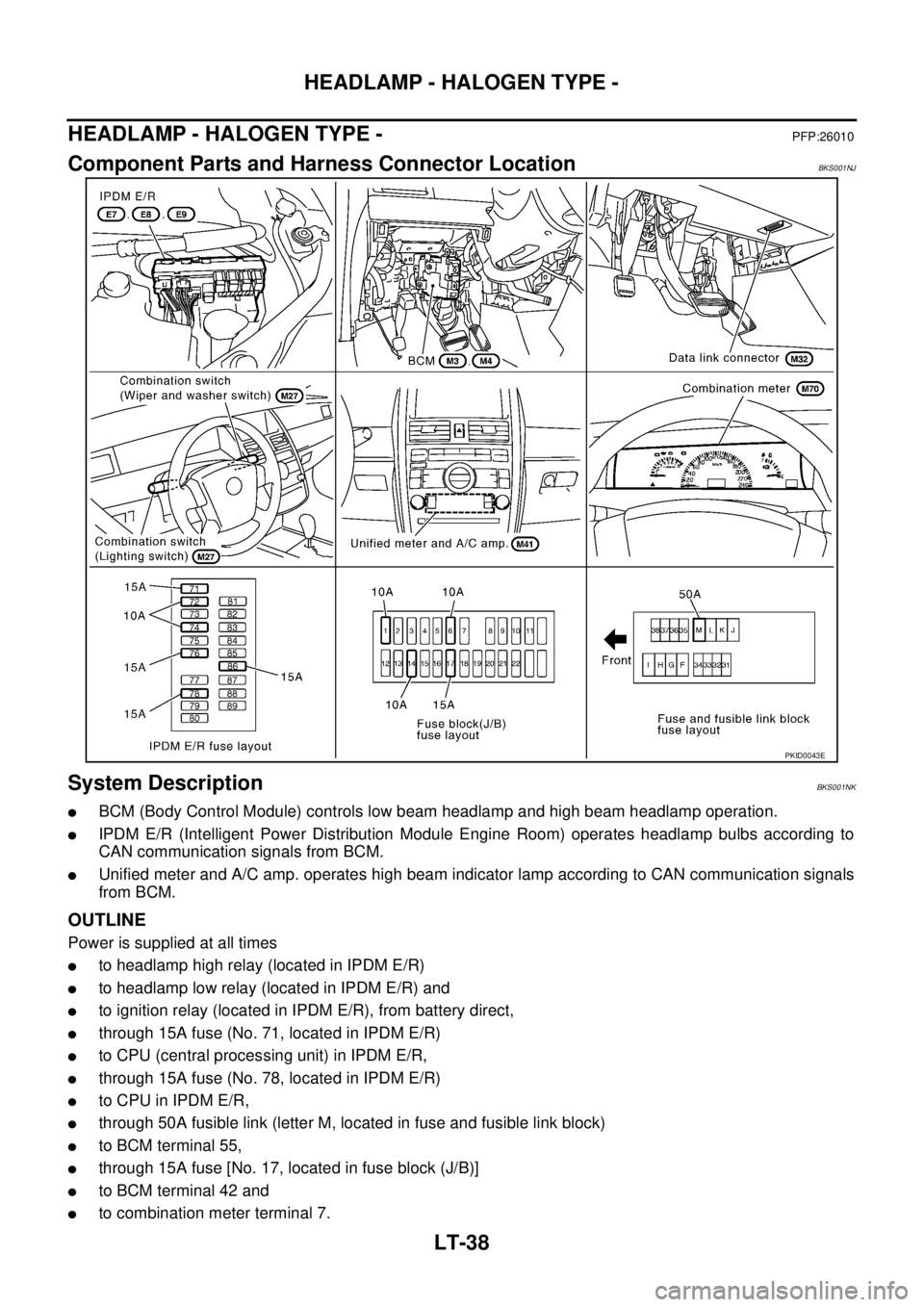
Component Parts and Harness Connector LocationBKS001NJ
System DescriptionBKS001NK
�BCM (Body Control Module) controls low beam headlamp and high beam headlamp operation.
�IPDM E/R (Intelligent Power Distribution Module Engine Room) operates headlamp bulbs according to
CAN communication signals from BCM.
�Unified meter and A/C amp. operates high beam indicator lamp according to CAN communication signals
from BCM.
OUTLINE
Power is supplied at all times
�to headlamp high relay (located in IPDM E/R)
�to headlamp low relay (located in IPDM E/R) and
�to ignition relay (located in IPDM E/R), from battery direct,
�through 15A fuse (No. 71, located in IPDM E/R)
�to CPU (central processing unit) in IPDM E/R,
�through 15A fuse (No. 78, located in IPDM E/R)
�to CPU in IPDM E/R,
�through 50A fusible link (letter M, located in fuse and fusible link block)
�to BCM terminal 55,
�through 15A fuse [No. 17, located in fuse block (J/B)]
�to BCM terminal 42 and
�to combination meter terminal 7.
PKID0043E
Page 2740 of 3502
LT-52
HEADLAMP - HALOGEN TYPE -
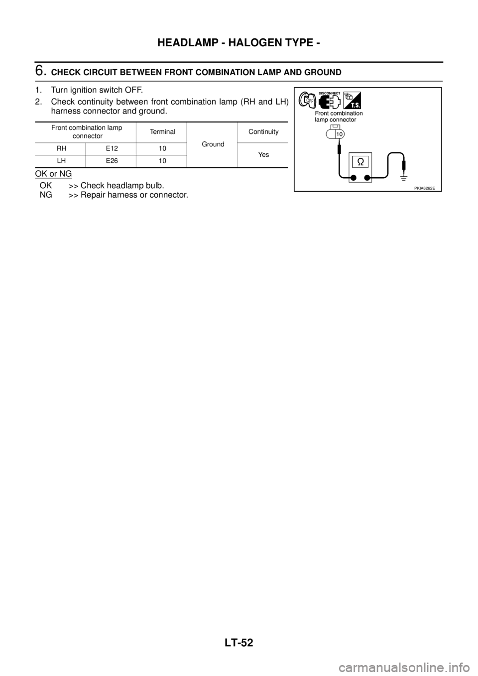
6. CHECK CIRCUIT BETWEEN FRONT COMBINATION LAMP AND GROUND
1. Turn ignition switch OFF.
2. Check continuity between front combination lamp (RH and LH)
harness connector and ground.
OK or NG
OK >> Check headlamp bulb.
NG >> Repair harness or connector.
Front combination lamp
connectorTerminal
GroundContinuity
RH E12 10
Ye s
LH E26 10
PKIA6262E
Page 2741 of 3502
HEADLAMP - HALOGEN TYPE -
LT-53
C
D
E
F
G
H
I
J
L
MA
B
LT
Headlamp High Does Not Illuminate (One Side)BKS001NW
1. CHECK BULB
Check headlamp bulb which does not illuminate.
OK or NG
OK >> GO TO 2.
NG >> Replace headlamp bulb.
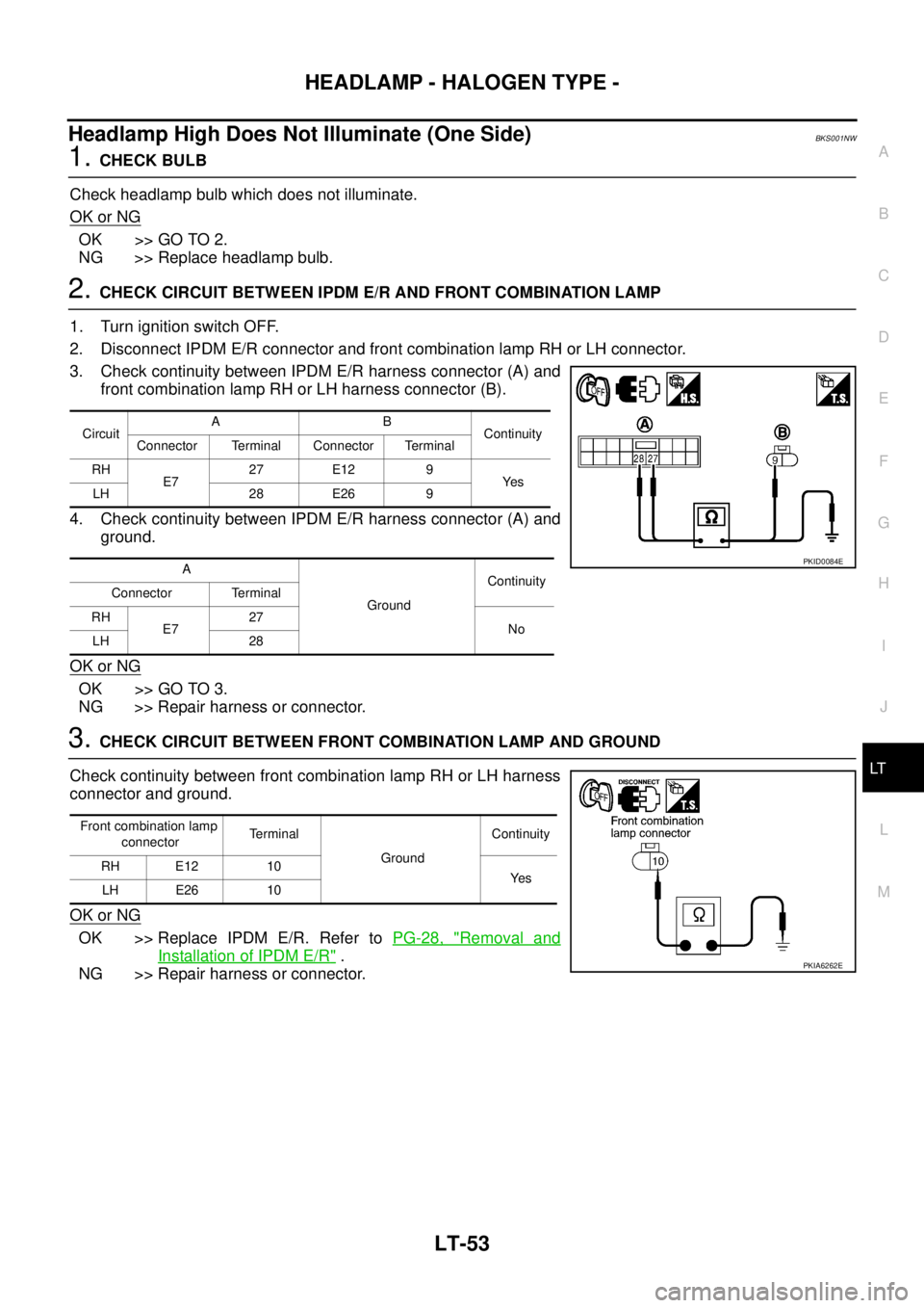
2. CHECK CIRCUIT BETWEEN IPDM E/R AND FRONT COMBINATION LAMP
1. Turn ignition switch OFF.
2. Disconnect IPDM E/R connector and front combination lamp RH or LH connector.
3. Check continuity between IPDM E/R harness connector (A) and
front combination lamp RH or LH harness connector (B).
4. Check continuity between IPDM E/R harness connector (A) and
ground.
OK or NG
OK >> GO TO 3.
NG >> Repair harness or connector.
3. CHECK CIRCUIT BETWEEN FRONT COMBINATION LAMP AND GROUND
Check continuity between front combination lamp RH or LH harness
connector and ground.
OK or NG
OK >> Replace IPDM E/R. Refer to PG-28, "Removal and
Installation of IPDM E/R" .
NG >> Repair harness or connector.
CircuitAB
Continuity
Connector Terminal Connector Terminal
RH
E727 E12 9
Ye s
LH 28 E26 9
A
GroundContinuity
Connector Terminal
RH
E727
No
LH 28
PKID0084E
Front combination lamp
connectorTerminal
GroundContinuity
RH E12 10
Ye s
LH E26 10
PKIA6262E
Page 2744 of 3502
LT-56
HEADLAMP - HALOGEN TYPE -
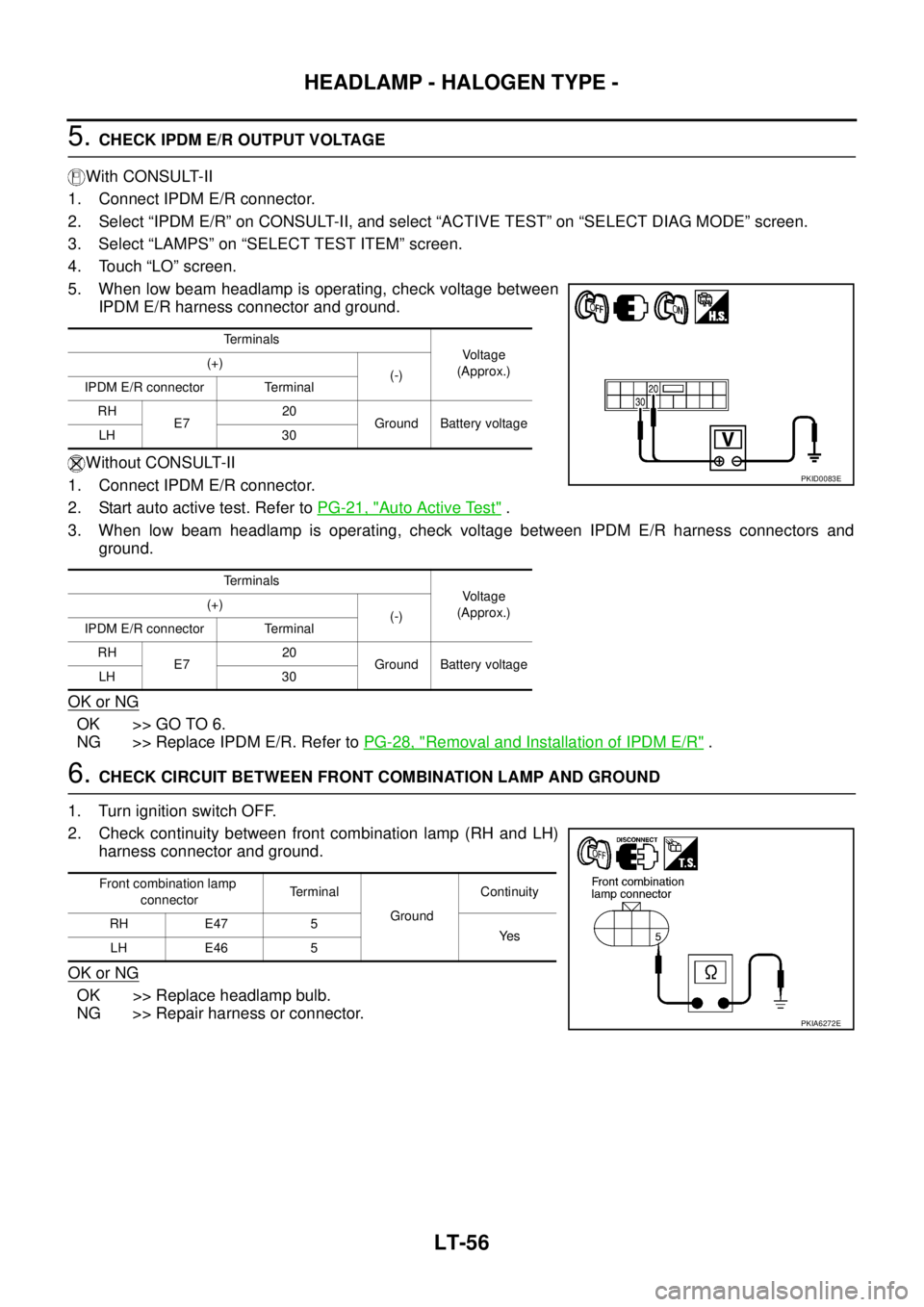
5. CHECK IPDM E/R OUTPUT VOLTAGE
With CONSULT-II
1. Connect IPDM E/R connector.
2. Select “IPDM E/R” on CONSULT-II, and select “ACTIVE TEST” on “SELECT DIAG MODE” screen.
3. Select “LAMPS” on “SELECT TEST ITEM” screen.
4. Touch “LO” screen.
5. When low beam headlamp is operating, check voltage between
IPDM E/R harness connector and ground.
Without CONSULT-II
1. Connect IPDM E/R connector.
2. Start auto active test. Refer to PG-21, "
Auto Active Test" .
3. When low beam headlamp is operating, check voltage between IPDM E/R harness connectors and
ground.
OK or NG
OK >> GO TO 6.
NG >> Replace IPDM E/R. Refer to PG-28, "
Removal and Installation of IPDM E/R" .
6. CHECK CIRCUIT BETWEEN FRONT COMBINATION LAMP AND GROUND
1. Turn ignition switch OFF.
2. Check continuity between front combination lamp (RH and LH)
harness connector and ground.
OK or NG
OK >> Replace headlamp bulb.
NG >> Repair harness or connector.
Terminals
Voltage
(Approx.) (+)
(-)
IPDM E/R connector Terminal
RH
E720
Ground Battery voltage
LH 30
Terminals
Voltage
(Approx.) (+)
(-)
IPDM E/R connector Terminal
RH
E720
Ground Battery voltage
LH 30
PKID0083E
Front combination lamp
connectorTerminal
GroundContinuity
RH E47 5
Ye s
LH E46 5
PKIA6272E
Page 2745 of 3502
HEADLAMP - HALOGEN TYPE -
LT-57
C
D
E
F
G
H
I
J
L
MA
B
LT
Headlamp Low Beam Does Not Illuminate (One Side)BKS001NZ
1. CHECK BULB
Check headlamp bulb which does not illuminate.
OK or NG
OK >> GO TO 2.
NG >> Replace headlamp bulb.
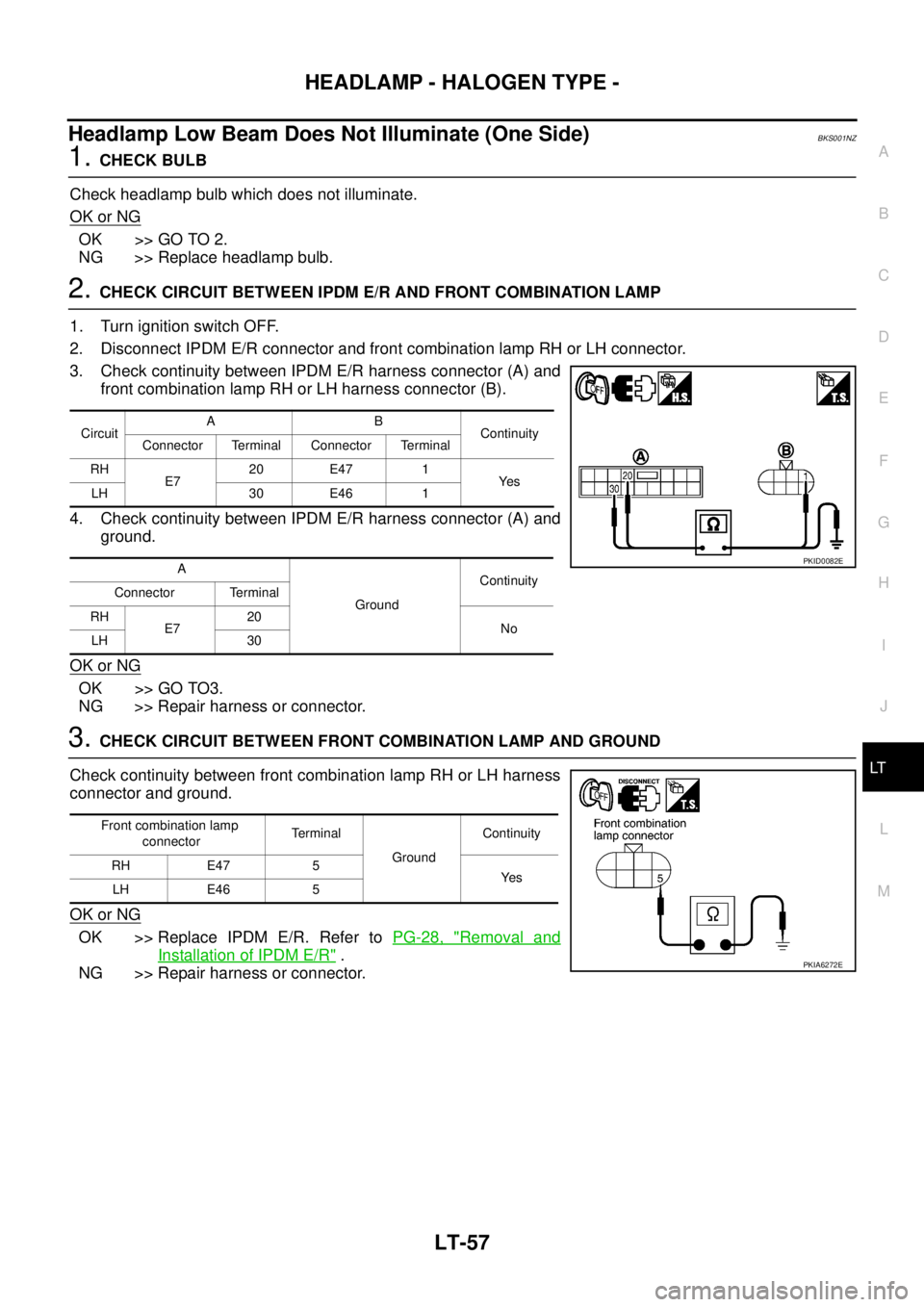
2. CHECK CIRCUIT BETWEEN IPDM E/R AND FRONT COMBINATION LAMP
1. Turn ignition switch OFF.
2. Disconnect IPDM E/R connector and front combination lamp RH or LH connector.
3. Check continuity between IPDM E/R harness connector (A) and
front combination lamp RH or LH harness connector (B).
4. Check continuity between IPDM E/R harness connector (A) and
ground.
OK or NG
OK >> GO TO3.
NG >> Repair harness or connector.
3. CHECK CIRCUIT BETWEEN FRONT COMBINATION LAMP AND GROUND
Check continuity between front combination lamp RH or LH harness
connector and ground.
OK or NG
OK >> Replace IPDM E/R. Refer to PG-28, "Removal and
Installation of IPDM E/R" .
NG >> Repair harness or connector.
CircuitAB
Continuity
Connector Terminal Connector Terminal
RH
E720 E47 1
Ye s
LH 30 E46 1
A
GroundContinuity
Connector Terminal
RH
E720
No
LH 30
PKID0082E
Front combination lamp
connectorTe r m i n a l
GroundContinuity
RH E47 5
Ye s
LH E46 5
PKIA6272E
Page 2750 of 3502
LT-62
HEADLAMP - HALOGEN TYPE -
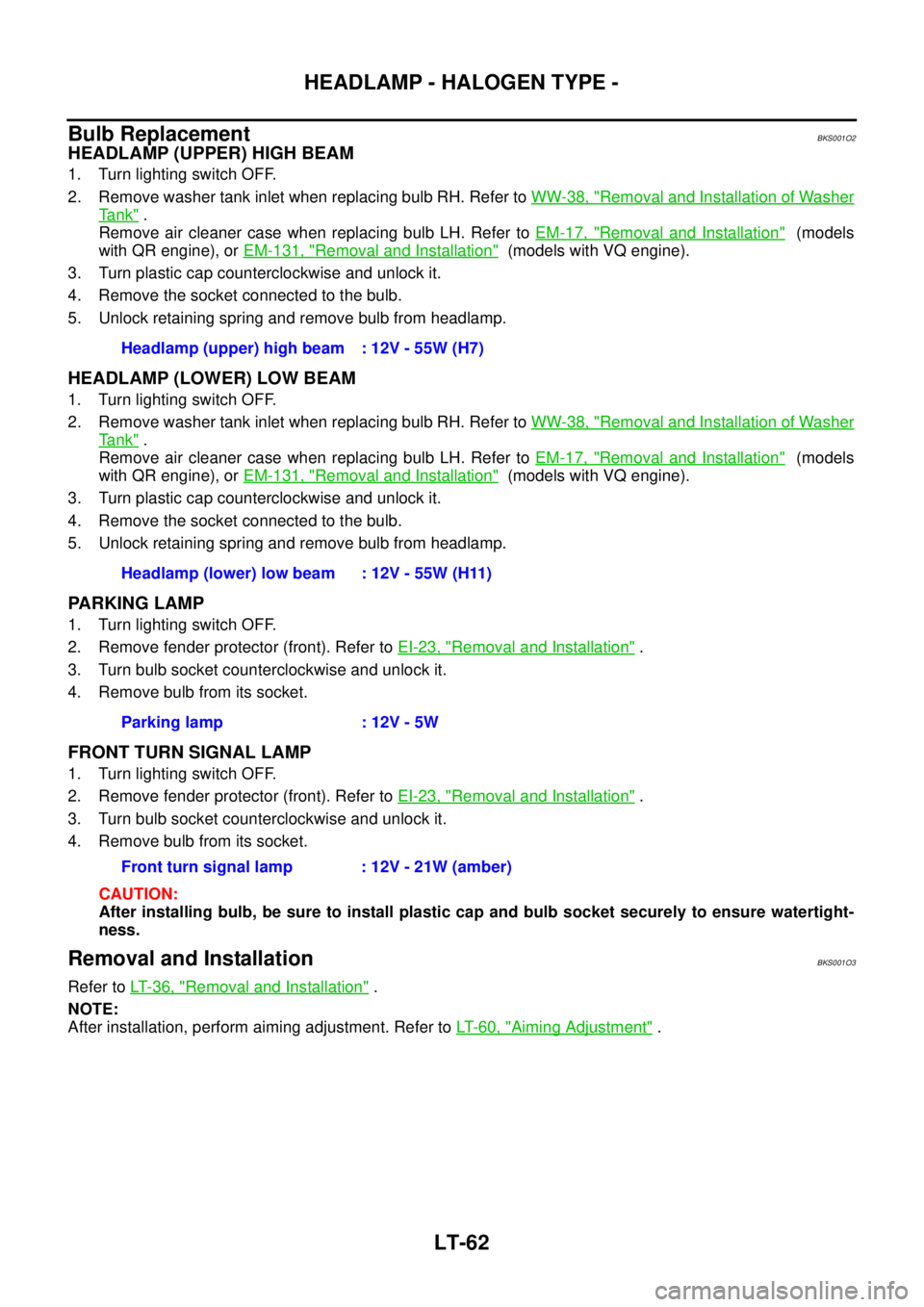
Bulb ReplacementBKS001O2
HEADLAMP (UPPER) HIGH BEAM
1. Turn lighting switch OFF.
2. Remove washer tank inlet when replacing bulb RH. Refer to WW-38, "
Removal and Installation of Washer
Ta n k" .
Remove air cleaner case when replacing bulb LH. Refer to EM-17, "
Removal and Installation" (models
with QR engine), or EM-131, "
Removal and Installation" (models with VQ engine).
3. Turn plastic cap counterclockwise and unlock it.
4. Remove the socket connected to the bulb.
5. Unlock retaining spring and remove bulb from headlamp.
HEADLAMP (LOWER) LOW BEAM
1. Turn lighting switch OFF.
2. Remove washer tank inlet when replacing bulb RH. Refer to WW-38, "
Removal and Installation of Washer
Ta n k" .
Remove air cleaner case when replacing bulb LH. Refer to EM-17, "
Removal and Installation" (models
with QR engine), or EM-131, "
Removal and Installation" (models with VQ engine).
3. Turn plastic cap counterclockwise and unlock it.
4. Remove the socket connected to the bulb.
5. Unlock retaining spring and remove bulb from headlamp.
PARKING LAMP
1. Turn lighting switch OFF.
2. Remove fender protector (front). Refer to EI-23, "
Removal and Installation" .
3. Turn bulb socket counterclockwise and unlock it.
4. Remove bulb from its socket.
FRONT TURN SIGNAL LAMP
1. Turn lighting switch OFF.
2. Remove fender protector (front). Refer to EI-23, "
Removal and Installation" .
3. Turn bulb socket counterclockwise and unlock it.
4. Remove bulb from its socket.
CAUTION:
After installing bulb, be sure to install plastic cap and bulb socket securely to ensure watertight-
ness.
Removal and InstallationBKS001O3
Refer to LT- 3 6 , "Removal and Installation" .
NOTE:
After installation, perform aiming adjustment. Refer to LT- 6 0 , "
Aiming Adjustment" . Headlamp (upper) high beam : 12V - 55W (H7)
Headlamp (lower) low beam : 12V - 55W (H11)
Parking lamp : 12V - 5W
Front turn signal lamp : 12V - 21W (amber)
Page 2751 of 3502
HEADLAMP - HALOGEN TYPE -
LT-63
C
D
E
F
G
H
I
J
L
MA
B
LT
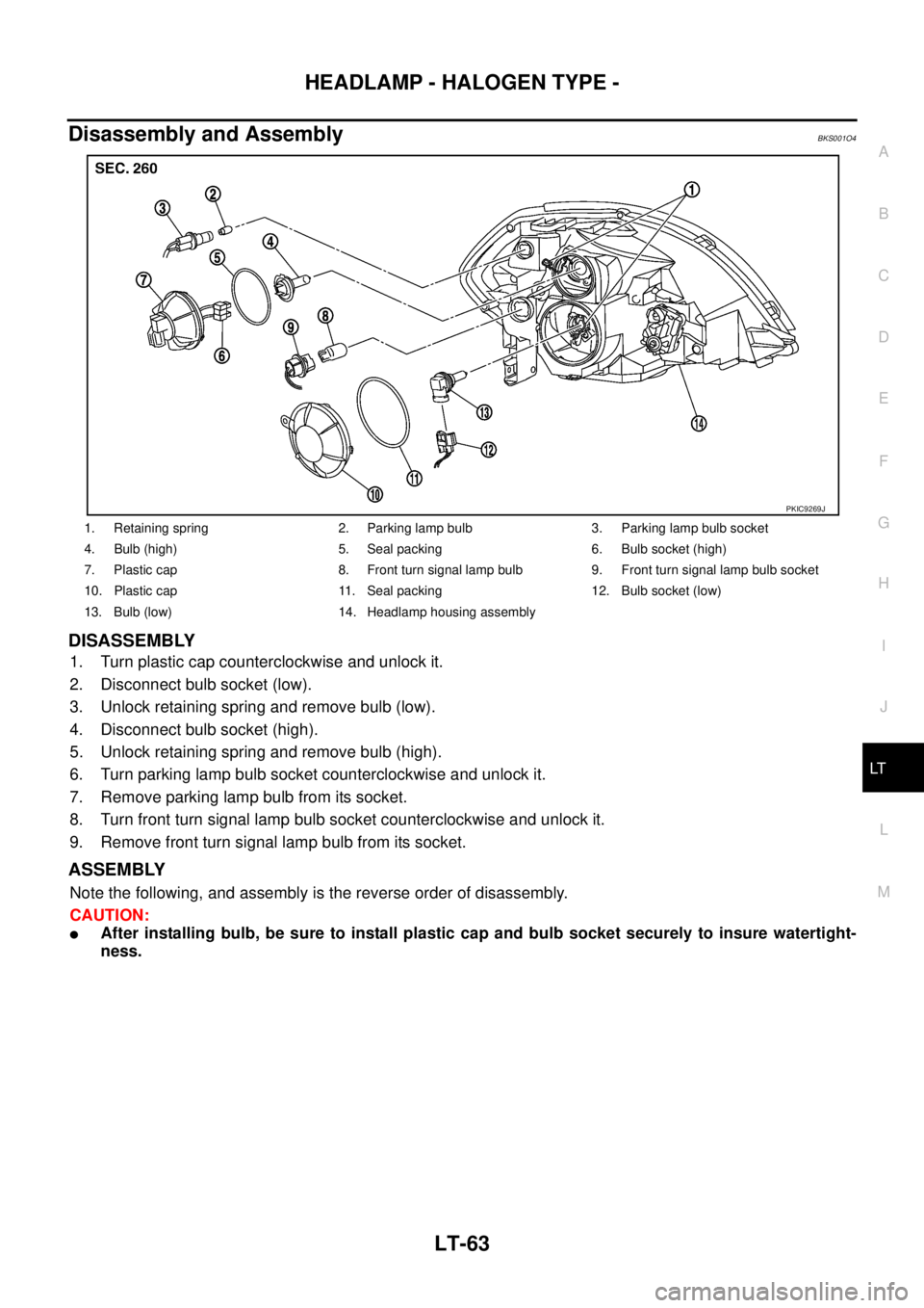
Disassembly and AssemblyBKS001O4
DISASSEMBLY
1. Turn plastic cap counterclockwise and unlock it.
2. Disconnect bulb socket (low).
3. Unlock retaining spring and remove bulb (low).
4. Disconnect bulb socket (high).
5. Unlock retaining spring and remove bulb (high).
6. Turn parking lamp bulb socket counterclockwise and unlock it.
7. Remove parking lamp bulb from its socket.
8. Turn front turn signal lamp bulb socket counterclockwise and unlock it.
9. Remove front turn signal lamp bulb from its socket.
ASSEMBLY
Note the following, and assembly is the reverse order of disassembly.
CAUTION:
�After installing bulb, be sure to install plastic cap and bulb socket securely to insure watertight-
ness.
1. Retaining spring 2. Parking lamp bulb 3. Parking lamp bulb socket
4. Bulb (high) 5. Seal packing 6. Bulb socket (high)
7. Plastic cap 8. Front turn signal lamp bulb 9. Front turn signal lamp bulb socket
10. Plastic cap 11. Seal packing 12. Bulb socket (low)
13. Bulb (low) 14. Headlamp housing assembly
PKIC9269J