Page 1200 of 3502

CVT-194
TRANSAXLE ASSEMBLY
REMOVAL
CAUTION:
The transaxle assembly itself cannot be removed from the vehicle. Remove the transaxle assembly
and engine assembly together from the vehicle.
1. Disconnect the batter cable from the negative terminal.
2. Remove engine undercover.
3. Remove exhaust front tube with power tool. Refer to EX-2, "
Removal and Installation" .
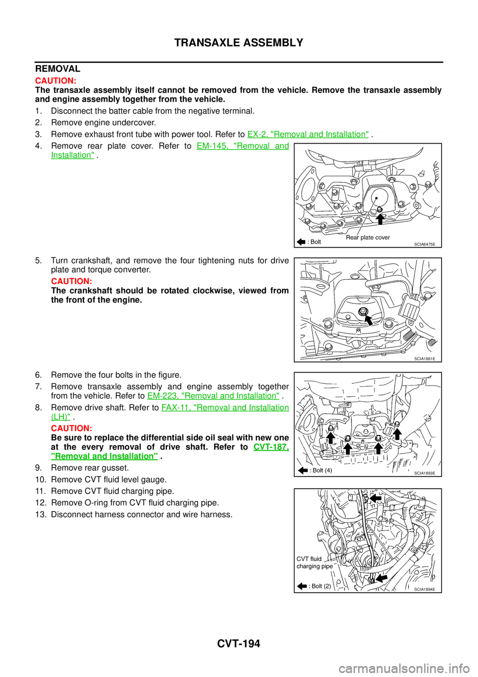
4. Remove rear plate cover. Refer to EM-145, "
Removal and
Installation" .
5. Turn crankshaft, and remove the four tightening nuts for drive
plate and torque converter.
CAUTION:
The crankshaft should be rotated clockwise, viewed from
the front of the engine.
6. Remove the four bolts in the figure.
7. Remove transaxle assembly and engine assembly together
from the vehicle. Refer to EM-223, "
Removal and Installation" .
8. Remove drive shaft. Refer to FA X - 11 , "
Removal and Installation
(LH)" .
CAUTION:
Be sure to replace the differential side oil seal with new one
at the every removal of drive shaft. Refer to CVT-187,
"Removal and Installation" .
9. Remove rear gusset.
10. Remove CVT fluid level gauge.
11. Remove CVT fluid charging pipe.
12. Remove O-ring from CVT fluid charging pipe.
13. Disconnect harness connector and wire harness.
SCIA6475E
SCIA1861E
SCIA1893E
SCIA1894E
Page 1231 of 3502
COMBINATION METERS
DI-25
C
D
E
F
G
H
I
J
L
MA
B
DI
Removal and Installation of Combination MeterBKS001SI
REMOVAL
1. Remove cluster lid A. Refer to IP-11, "Removal and Installation" .
2. Remove screws (3) and remove combination meter.
INSTALLATION
Installation is the reverse order of removal.
Disassembly and Assembly of Combination MeterBKS001SJ
SKIB0867E
SKIB0868E
1. Unified meter control unit assembly 2. Upper housing 3. Front cover
4. Odo/trip meter 5. Screw
SKIA6276J
Page 1232 of 3502
DI-26
COMBINATION METERS
DISASSEMBLY
1. Disengage the tabs (8) to separate front cover.
2. Disconnect odo/trip meter connector.
3. Disengage the tabs (8) to separate upper housing.
4. Remove screws (1) and remove odo/trip meter.
ASSEMBLY
Assembly is the reverse order of disassembly.
SKIB0868E
SKIA7244E
Page 2055 of 3502

SQUEAK AND RATTLE TROUBLE DIAGNOSES
EI-7
C
D
E
F
G
H
J
K
L
MA
B
EI
FELT CLOTHTAPE
Used to insulate where movement does not occur. Ideal for instrument panel applications.
68370-4B000: 15 × 25 mm (0.59 × 0.98 in) pad/68239-13E00: 5 mm (0.20 in) wide tape roll
The following materials, not available through NISSAN Parts Department, can also be used to repair squeaks
and rattles.
UHMW(TEFLON) TAPE
Insulates where slight movement is present. Ideal for instrument panel applications.
SILICONE GREASE
Used in place of UHMW tape that will be visible or not fit.
Note: Will only last a few months.
SILICONE SPRAY
Use when grease cannot be applied.
DUCT TAPE
Use to eliminate movement.
CONFIRM THE REPAIR
Confirm that the cause of a noise is repaired by test driving the vehicle. Operate the vehicle under the same
conditions as when the noise originally occurred. Refer to the notes on the Diagnostic Worksheet.
Generic Squeak and Rattle TroubleshootingBIS0011B
Refer to Table of Contents for specific component removal and installation information.
INSTRUMENT PANEL
Most incidents are caused by contact and movement between:
1. Cluster lid A and instrument panel
2. Acrylic lens and combination meter housing
3. Instrument panel to front pillar garnish
4. Instrument panel to windshield
5. Instrument panel mounting pins
6. Wiring harnesses behind the combination meter
7. A/C defroster duct and duct joint
These incidents can usually be located by tapping or moving the components to duplicate the noise or by
pressing on the components while driving to stop the noise. Most of these incidents can be repaired by apply-
ing felt cloth tape or silicon spray (in hard to reach areas). Urethane pads can be used to insulate wiring har-
ness.
CAUTION:
Do not use silicone spray to isolate a squeak or rattle. If you saturate the area with silicone, you will
not be able to recheck the repair.
CENTER CONSOLE
Components to pay attention to include:
1. Shifter assembly cover to finisher
2. A/C control unit and cluster lid C
3. Wiring harnesses behind audio and A/C control unit
The instrument panel repair and isolation procedures also apply to the center console.
DOORS
Pay attention to the:
1. Finisher and inner panel making a slapping noise
2. Inside handle escutcheon to door finisher
3. Wiring harnesses tapping
4. Door striker out of alignment causing a popping noise on starts and stops
Tapping or moving the components or pressing on them while driving to duplicate the conditions can isolate
many of these incidents. You can usually insulate the areas with felt cloth tape or insulator foam blocks to
repair the noise.
Page 2070 of 3502

EI-22
COWL TOP
REMOVAL
1. Remove front wiper arm (LH/RH) from vehicle. Refer to WW-34, "Removal and Installation of Front Wiper
Arms, Adjustment of Wiper Arms Stop Location" .
2. Remove cowl top seal rubber together with mounting clips.
3. Remove food hinge cover (LH/RH).
4. Remove front end clips of cowl top cover (LH/RH).
5. Disengage cowl top cover (LH) rear end blind clip, and then remove it.
6. Disengage cowl top cover (RH) rear end blind clip, and then remove it.
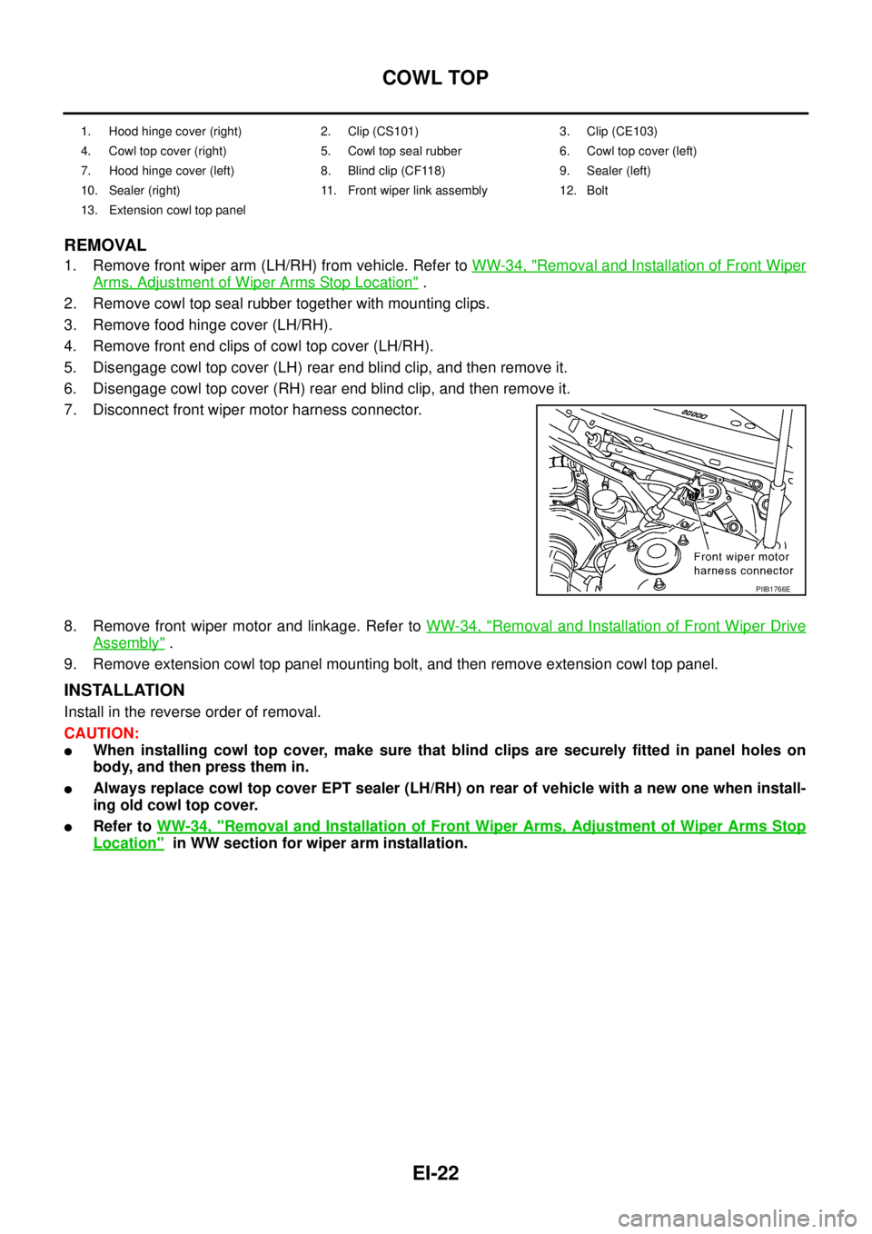
7. Disconnect front wiper motor harness connector.
8. Remove front wiper motor and linkage. Refer to WW-34, "
Removal and Installation of Front Wiper Drive
Assembly" .
9. Remove extension cowl top panel mounting bolt, and then remove extension cowl top panel.
INSTALLATION
Install in the reverse order of removal.
CAUTION:
�When installing cowl top cover, make sure that blind clips are securely fitted in panel holes on
body, and then press them in.
�Always replace cowl top cover EPT sealer (LH/RH) on rear of vehicle with a new one when install-
ing old cowl top cover.
�Refer to WW-34, "Removal and Installation of Front Wiper Arms, Adjustment of Wiper Arms Stop
Location" in WW section for wiper arm installation.
1. Hood hinge cover (right) 2. Clip (CS101) 3. Clip (CE103)
4. Cowl top cover (right) 5. Cowl top seal rubber 6. Cowl top cover (left)
7. Hood hinge cover (left) 8. Blind clip (CF118) 9. Sealer (left)
10. Sealer (right) 11. Front wiper link assembly 12. Bolt
13. Extension cowl top panel
PIIB1766E
Page 2076 of 3502
EI-28
WINDSHIELD MOLDING
WINDSHIELD MOLDINGPFP:72700
Removal and InstallationBIS0011M
REMOVAL AND INSTALLATION
Refer to GW-11, "Removal and Installation" in GW section for removal and installation of windshield and wind-
shield molding.
PIIB1021E
1. Dam rubber 2. Windshield upper molding 3. Roof side molding
4. Fastener (LH/RH) 5. Windshield glass 6. Spacer
7. Roof 8. Panel 9. Adhesive
10. Front pillar outer panel 11. Cowl top cover (LH/RH) 12. Cowl box side
Page 2078 of 3502

EI-30
DOOR OUTSIDE MOLDING
DOOR OUTSIDE MOLDING PFP:82820
Removal and InstallationBIS0011O
FRONT DOOR OUTSIDE MOLDING
Removal
1. Fully open door window.
2. Remove door trim. Refer to EI-35, "
DOOR FINISHER" .
3. Remove door corner cover (inner). Refer to GW-74, "
DOOR MIRROR" .
4. Disconnect harness connector for tweeter (only for models with tweeter). Refer to AV- 1 7 , "
Removal and
Installation of Tweeter" .
5. Remove door mirror. Refer to GW-74, "
DOOR MIRROR" .
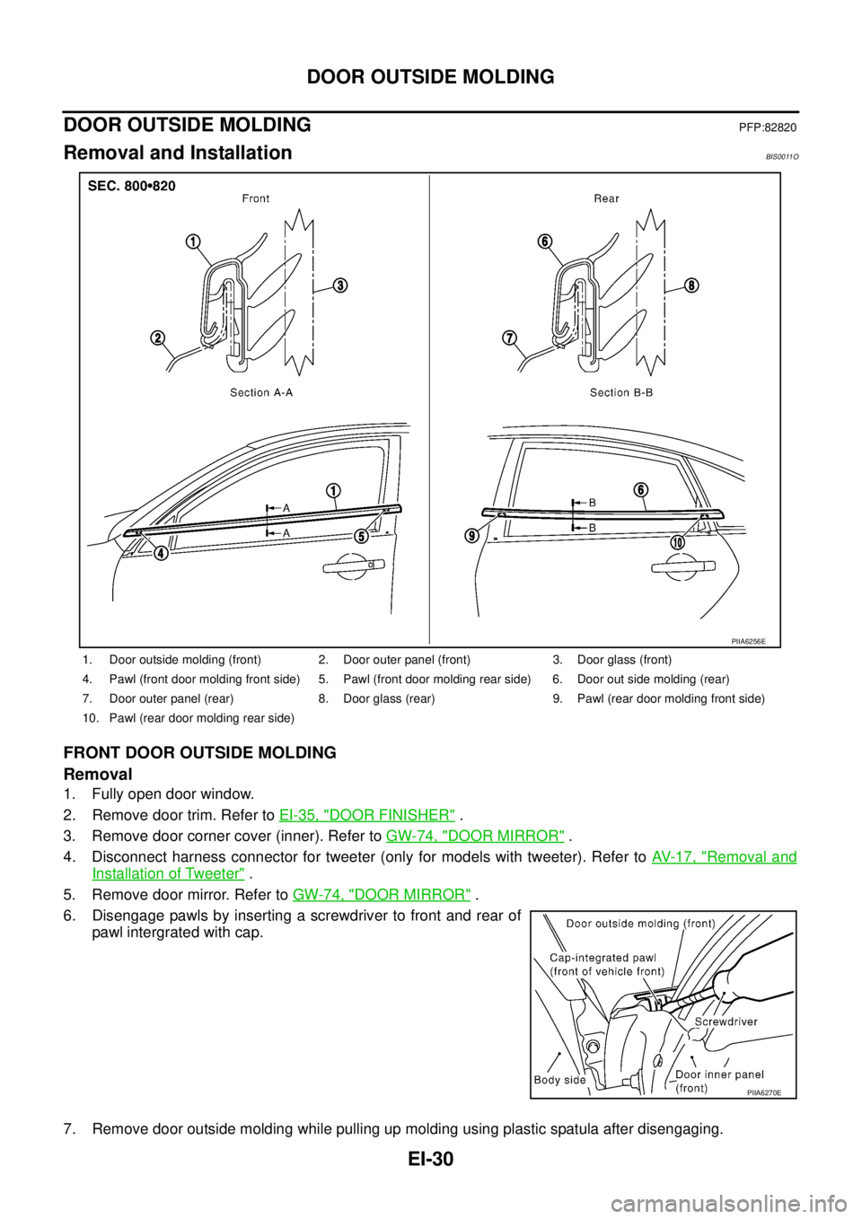
6. Disengage pawls by inserting a screwdriver to front and rear of
pawl intergrated with cap.
7. Remove door outside molding while pulling up molding using plastic spatula after disengaging.
1. Door outside molding (front) 2. Door outer panel (front) 3. Door glass (front)
4. Pawl (front door molding front side) 5. Pawl (front door molding rear side) 6. Door out side molding (rear)
7. Door outer panel (rear) 8. Door glass (rear) 9. Pawl (rear door molding front side)
10. Pawl (rear door molding rear side)
PIIA6256E
PIIA6270E
Page 2079 of 3502
DOOR OUTSIDE MOLDING
EI-31
C
D
E
F
G
H
J
K
L
MA
B
EI
CAUTION:
�Be careful not to apply excessive force when removing because it is easy to deform parts.
�After removal, visually inspect molding, and if it is deformed, replace it with new molding.
REAR DOOR OUTSIDE MOLDING
Removal
1. Fully open door window.
2. Remove door trim. Refer to EI-35, "
DOOR FINISHER" .
3. Remove door corner cover inner and outer. Refer to GW-50, "
REAR DOOR GLASS AND REGULATOR" .
4. Disengage pawls by inserting a screwdriver to front and rear of pawl integrated with cap.
5. Remove door outside molding while pulling up molding using plastic spatula after disengaging.
CAUTION:
�Be careful not to apply excessive force when removing because it is easy to deform parts.
�After removal, visually inspect molding, and if it is deformed, replace it with new molding.
Installation
Install in the reverse order of removal.
NOTE:
Molding rear end is flush with door sash rear end when installing.