Page 3097 of 3502

HARNESS
PG-63
C
D
E
F
G
H
I
J
L
MA
B
PG
Wiring Diagram Codes (Cell Codes) BKS002FS
Use the chart below to find out what each wiring diagram code stands for.
Refer to the wiring diagram code in the alphabetical index to find the location (page number) of each wiring
diagram.
Code Section Wiring Diagram Name
A/C ATC Air Conditioner
ABS BRC Anti-Lock Brake System
AFS LT Adaptive Front Lighting System
APPS1 EC Accelerator Pedal Position Sensor
APPS2 EC Accelerator Pedal Position Sensor
APPS3 EC Accelerator Pedal Position Sensor
ASC/BS EC Automatic Speed Control Device (ASCD) Brake Switch
ASC/SW EC Automatic Speed Control Device (ASCD) Steering Switch
ASCBOF EC Automatic Speed Control Device (ASCD) Brake Switch
ASCIND EC Automatic Speed Control Device (ASCD) Indicator
AT/IND DI A/T Indicator Lamp
AUDIO AV Audio
AUT/DP SE Automatic Drive Positioner
AUTO/L LT Auto Light Control
BA/FTS AT A/T Fluid Temperature Sensor and TCM Power Supply
BACK/L LT Back-Up Lamp
BRK/SW EC Brake Switch
CAN AT CAN Communication Line
CAN CVT CAN Communication Line
CAN EC CAN Communication Line
CAN LAN CAN System
CHARGE SC Charging System
CHIME DI Warning Chime
CIGAR WW Cigarette Lighter
COMBSW LT Combination Switch
COMM AV Audio Visual Communication Line
COOL/F EC Cooling Fan Control
CVTIND DI CVT Indicator Lamp
D/LOCK BL Power Door Lock
DEF GW Rear Window Defogger
ECM/PW EC ECM Power Supply for Back-Up
ECTS EC Engine Coolant Temperature Sensor
EMNT EC Electronic Controlled Engine Mount
ENGSS AT Engine Speed Signal
ETC1 EC Electric Throttle Control Function
ETC2 EC Electric Throttle Control Motor Relay
ETC3 EC Electric Throttle Control Motor
F/FOG LT Front Fog Lamp
F/LID BL Fuel Lid Opener
F/PUMP EC Fuel Pump
FRO2 EC Heated Oxygen Sensor 1 Heater
Page 3098 of 3502

PG-64
HARNESS
FRO2B1 EC Heated Oxygen Sensor 1 Heater Bank 1
FRO2B2 EC Heated Oxygen Sensor 1 Heater Bank 2
FTS CVT CVT Fluid Temperature Sensor Circuit
H/AIM LT Headlamp Aiming Control System
H/LAMP LT Headlamp
HLC WW Headlamp Washer
HORN WW Horn
HO2S1 EC Heated Oxygen Sensor 1
HSEAT SE Heated Seat
I/KEY BL Intelligent Key System
IATSEN EC Intake Air Temperature Sensor
IGNSYS EC Ignition System
ILL LT Illumination
INF/D AV Vehicle Information and Integrated Switch System
INJECT EC Injector
INT/L LT Vanity Mirror Lamp
IVC EC Intake Valve Timing Control Solenoid Valve
IVCB1 EC Intake Valve Timing Control Solenoid Valve Bank 1
IVCB2 EC Intake Valve Timing Control Solenoid Valve Bank 2
KEYLES BL Remote Keyless Entry System
KS EC Knock Sensor
L/USSV CVT Lock-Up Select Solenoid Valve
LPSV AT Line Pressure Solenoid Valve
LPSV CVT Line Pressure Solenoid Valve
M/SEAT SE Air Massage Seat
MAFS EC Mass Air Flow Sensor
MAIN AT Main Power Supply and Ground Circuit
MAIN EC Main Power Supply and Ground Circuit
METER DI Speedometer, Tachometer, Temp. and Fuel Gauges
MIL/DL EC MIL & Data Link Connector
MIRROR GW Power Door Mirror
MMSW CVT Manual Mode Switch
NATS BL Nissan Anti-Theft System
NONDTC AT Non-Detective Items
NONDTC CVT Non-Detective Items
O2S1B1 EC Heated Oxygen Sensor 1 Bank 1
O2S1B2 EC Heated Oxygen Sensor 1 Bank 2
OVRCSV AT Overrun Clutch Solenoid Valve
PHASE EC Camshaft Position Sensor (PHASE)
PHSB1 EC Camshaft Position Sensor (PHASE) (Bank1)
PHSB2 EC Camshaft Position Sensor (PHASE) (Bank2)
PNP/SW CVT Park/Neutral Position Switch
PNP/SW EC Park/Neutral Position Switch
POS EC Crankshaft Position Sensor (CKPS) (POS) Code Section Wiring Diagram Name
Page 3194 of 3502
RSU-2
PRECAUTIONS
PRECAUTIONSPFP:00001
CautionBES0003W
�When installing rubber bushings, final tightening must be performed under unladen conditions with tires
on ground. Oil will shorten the life of rubber bushings. Be sure to wipe off any spilled oil.
–Unladen conditions mean that fuel, engine coolant and lubricant are full. A spare tire, a jack, hand tools
and mats are in designated positions.
�After servicing suspension parts, be sure to check wheel alignment.
�Self-locks nut are not reusable. Always use new ones when installing. Since new self-lock nut are pre-
oiled, tighten as they are.
Page 3197 of 3502
REAR SUSPENSION ASSEMBLY
RSU-5
C
D
F
G
H
I
J
K
L
MA
B
RSU
REAR SUSPENSION ASSEMBLYPFP:55020
On-Vehicle Inspection BES00040
Make sure that the mounting conditions (looseness, back lash) of each components and component status
(wear, damage) are normal.
INSPECTION OF SUSPENSION ARM BALL JOINT END PLAY
Measure axial end play by placing an iron pry bar or a similar item between suspension arm and axle housing
prying up and down.
CAUTION:
Be careful not to damage ball joint boot. Do not damage installation position by applying excessive
force.
SHOCK ABSORBER INSPECTION
Check for oil leakage, damage, and breakage of installation positions.
Wheel Alignment InspectionBES00041
DESCRIPTION
Measure the wheel alignment under unladen conditions.
NOTE:
“Unladen conditions” mean that fuel, engine coolant, and lubricant are full. A spare tire, a jack, hand tools and
mats are in designated positions.
PRELIMINARY CHECK
1. Check tires for improper air pressure and wear.
2. Check road wheels for runout. Refer to WT-3, "
ROAD WHEEL" .
3. Check wheel bearing axial end play. Refer to RAX-3, "
WHEEL BEARING INSPECTION" .
4. Check suspension arm ball joint axial end play. Refer to RSU-11, "
Ball Joint Inspection" .
5. Check shock absorber operation.
6. Check each mounting point of axle housing and suspension for looseness and deformation.
7. Check each link, arm, and member for cracks, deformation, and other damage.
8. Check vehicle height (posture).
CAMBER INSPECTION
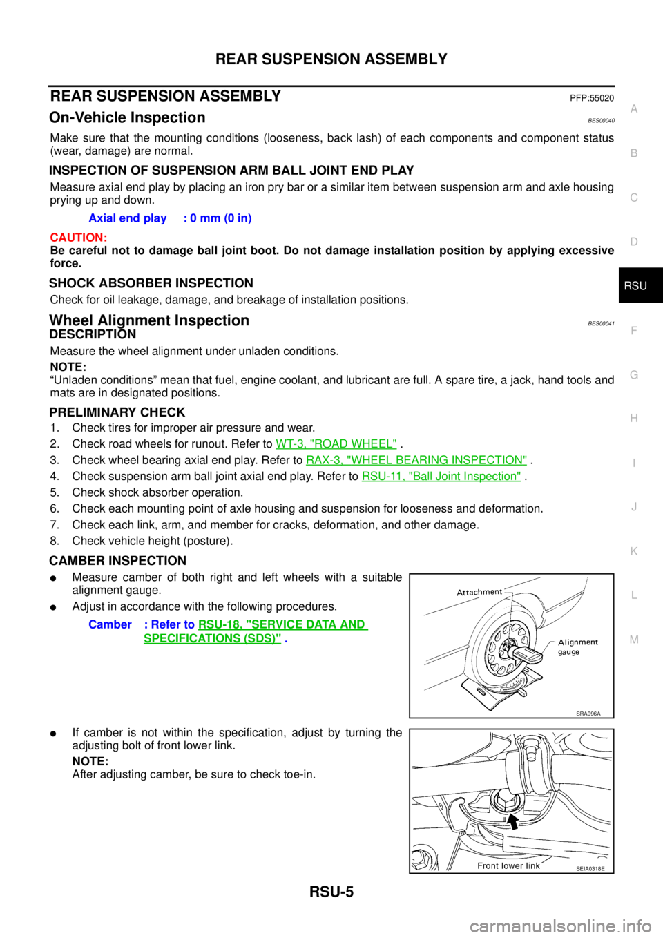
�Measure camber of both right and left wheels with a suitable
alignment gauge.
�Adjust in accordance with the following procedures.
�If camber is not within the specification, adjust by turning the
adjusting bolt of front lower link.
NOTE:
After adjusting camber, be sure to check toe-in.Axial end play : 0 mm (0 in)
Camber : Refer to RSU-18, "
SERVICE DATA AND
SPECIFICATIONS (SDS)" .
SRA096A
SEIA0318E
Page 3210 of 3502
RSU-18
SERVICE DATA AND SPECIFICATIONS (SDS)
SERVICE DATA AND SPECIFICATIONS (SDS)PFP:00030
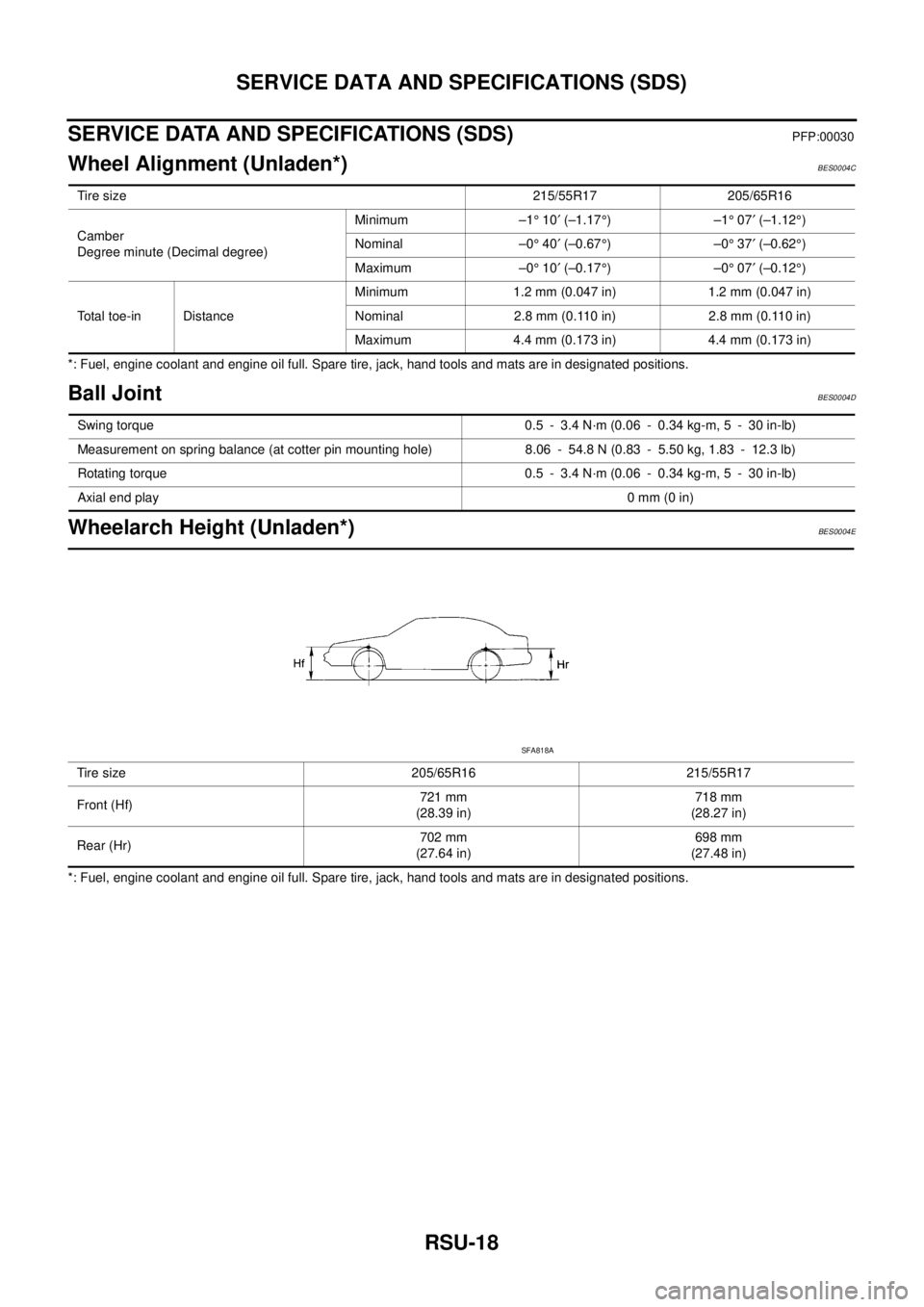
Wheel Alignment (Unladen*)BES0004C
*: Fuel, engine coolant and engine oil full. Spare tire, jack, hand tools and mats are in designated positions.
Ball JointBES0004D
Wheelarch Height (Unladen*)BES0004E
*: Fuel, engine coolant and engine oil full. Spare tire, jack, hand tools and mats are in designated positions.Tire size 215/55R17 205/65R16
Camber
Degree minute (Decimal degree)Minimum –1° 10′ (–1.17°)–1° 07′ (–1.12°)
Nominal –0° 40′ (–0.67°)–0° 37′ (–0.62°)
Maximum –0° 10′ (–0.17°)–0° 07′ (–0.12°)
Total toe-in Distance Minimum 1.2 mm (0.047 in) 1.2 mm (0.047 in)
Nominal 2.8 mm (0.110 in) 2.8 mm (0.110 in)
Maximum 4.4 mm (0.173 in) 4.4 mm (0.173 in)
Swing torque 0.5 - 3.4 N·m (0.06 - 0.34 kg-m, 5 - 30 in-lb)
Measurement on spring balance (at cotter pin mounting hole) 8.06 - 54.8 N (0.83 - 5.50 kg, 1.83 - 12.3 lb)
Rotating torque 0.5 - 3.4 N·m (0.06 - 0.34 kg-m, 5 - 30 in-lb)
Axial end play0 mm (0 in)
Tire size 205/65R16 215/55R17
Front (Hf)721 mm
(28.39 in)718 mm
(28.27 in)
Rear (Hr)702 mm
(27.64 in)698 mm
(27.48 in)
SFA818A