Page 3006 of 3502
MA-28
ENGINE MAINTENANCE (VQ23DE AND VQ35DE)
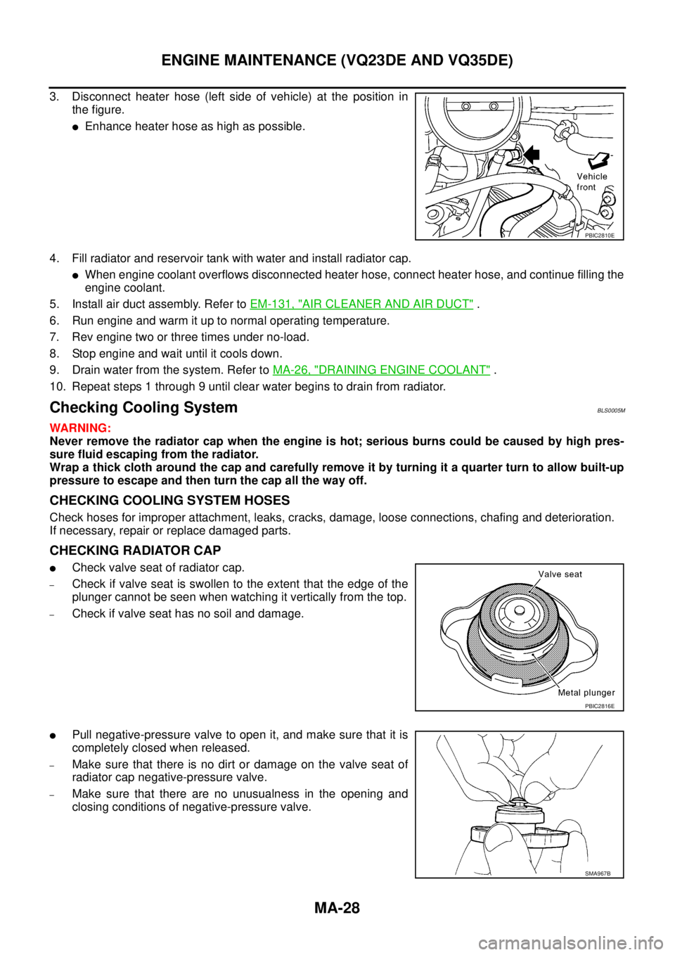
3. Disconnect heater hose (left side of vehicle) at the position in
the figure.
�Enhance heater hose as high as possible.
4. Fill radiator and reservoir tank with water and install radiator cap.
�When engine coolant overflows disconnected heater hose, connect heater hose, and continue filling the
engine coolant.
5. Install air duct assembly. Refer to EM-131, "
AIR CLEANER AND AIR DUCT" .
6. Run engine and warm it up to normal operating temperature.
7. Rev engine two or three times under no-load.
8. Stop engine and wait until it cools down.
9. Drain water from the system. Refer to MA-26, "
DRAINING ENGINE COOLANT" .
10. Repeat steps 1 through 9 until clear water begins to drain from radiator.
Checking Cooling SystemBLS0005M
WARNING:
Never remove the radiator cap when the engine is hot; serious burns could be caused by high pres-
sure fluid escaping from the radiator.
Wrap a thick cloth around the cap and carefully remove it by turning it a quarter turn to allow built-up
pressure to escape and then turn the cap all the way off.
CHECKING COOLING SYSTEM HOSES
Check hoses for improper attachment, leaks, cracks, damage, loose connections, chafing and deterioration.
If necessary, repair or replace damaged parts.
CHECKING RADIATOR CAP
�Check valve seat of radiator cap.
–Check if valve seat is swollen to the extent that the edge of the
plunger cannot be seen when watching it vertically from the top.
–Check if valve seat has no soil and damage.
�Pull negative-pressure valve to open it, and make sure that it is
completely closed when released.
–Make sure that there is no dirt or damage on the valve seat of
radiator cap negative-pressure valve.
–Make sure that there are no unusualness in the opening and
closing conditions of negative-pressure valve.
PBIC2810E
PBIC2816E
SMA967B
Page 3008 of 3502
MA-30
ENGINE MAINTENANCE (VQ23DE AND VQ35DE)
Checking Fuel LinesBLS0005N
Inspect fuel lines, fuel filler cap and fuel tank for improper attach-
ment, leaks, cracks, damage, loose connections, chafing or deterio-
ration.
If necessary, repair or replace damaged parts.
Changing Air Cleaner FilterBLS0005O
VISCOUS PAPER TYPE
The viscous paper type filter does not need cleaning between replacement intervals. Refer to MA-8, "PERI-
ODIC MAINTENANCE" .
Removal
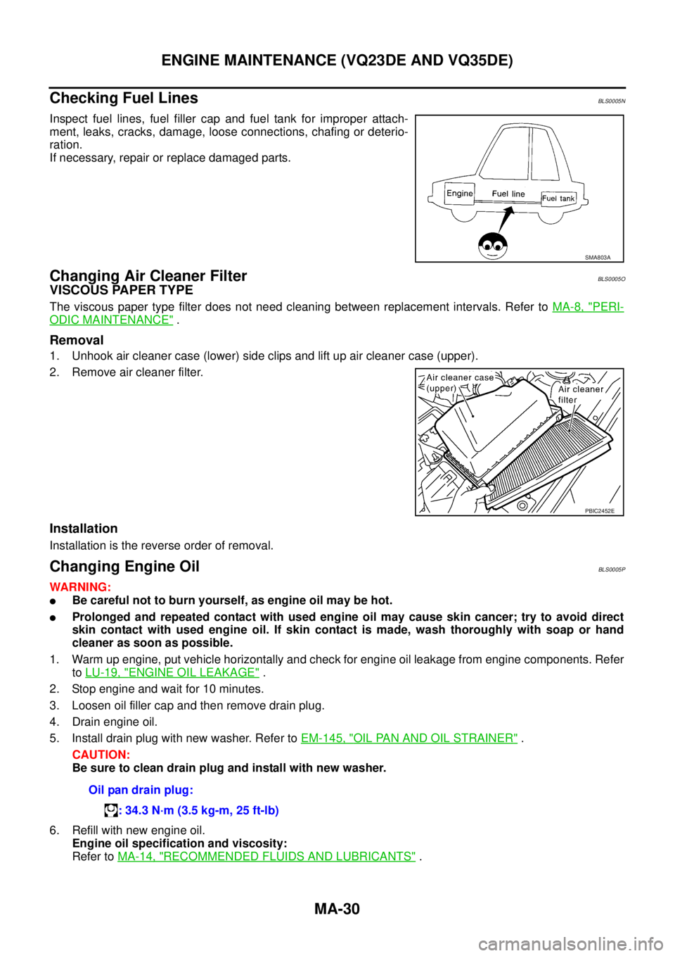
1. Unhook air cleaner case (lower) side clips and lift up air cleaner case (upper).
2. Remove air cleaner filter.
Installation
Installation is the reverse order of removal.
Changing Engine OilBLS0005P
WARNING:
�Be careful not to burn yourself, as engine oil may be hot.
�Prolonged and repeated contact with used engine oil may cause skin cancer; try to avoid direct
skin contact with used engine oil. If skin contact is made, wash thoroughly with soap or hand
cleaner as soon as possible.
1. Warm up engine, put vehicle horizontally and check for engine oil leakage from engine components. Refer
to LU-19, "
ENGINE OIL LEAKAGE" .
2. Stop engine and wait for 10 minutes.
3. Loosen oil filler cap and then remove drain plug.
4. Drain engine oil.
5. Install drain plug with new washer. Refer to EM-145, "
OIL PAN AND OIL STRAINER" .
CAUTION:
Be sure to clean drain plug and install with new washer.
6. Refill with new engine oil.
Engine oil specification and viscosity:
Refer to MA-14, "
RECOMMENDED FLUIDS AND LUBRICANTS" .
SMA803A
PBIC2452E
Oil pan drain plug:
: 34.3 N·m (3.5 kg-m, 25 ft-lb)
Page 3009 of 3502
ENGINE MAINTENANCE (VQ23DE AND VQ35DE)
MA-31
C
D
E
F
G
H
I
J
K
MA
B
MA
Engine oil capacity (Approximate):
Unit: (lmp qt)
CAUTION:
�When filling engine oil, do not pull out oil level gauge.
�The refill capacity depends on the engine oil temperature and drain time. Use these specifica-
tions for reference only.
�Always use oil level gauge to the determine when the proper amount of engine oil is in the
engine.
NOTE:
The same quantity both VQ23DE and VQ35DE
7. Warm up engine and check area around drain plug and oil filter for engine oil leakage.
8. Stop engine and wait for 10 minutes.
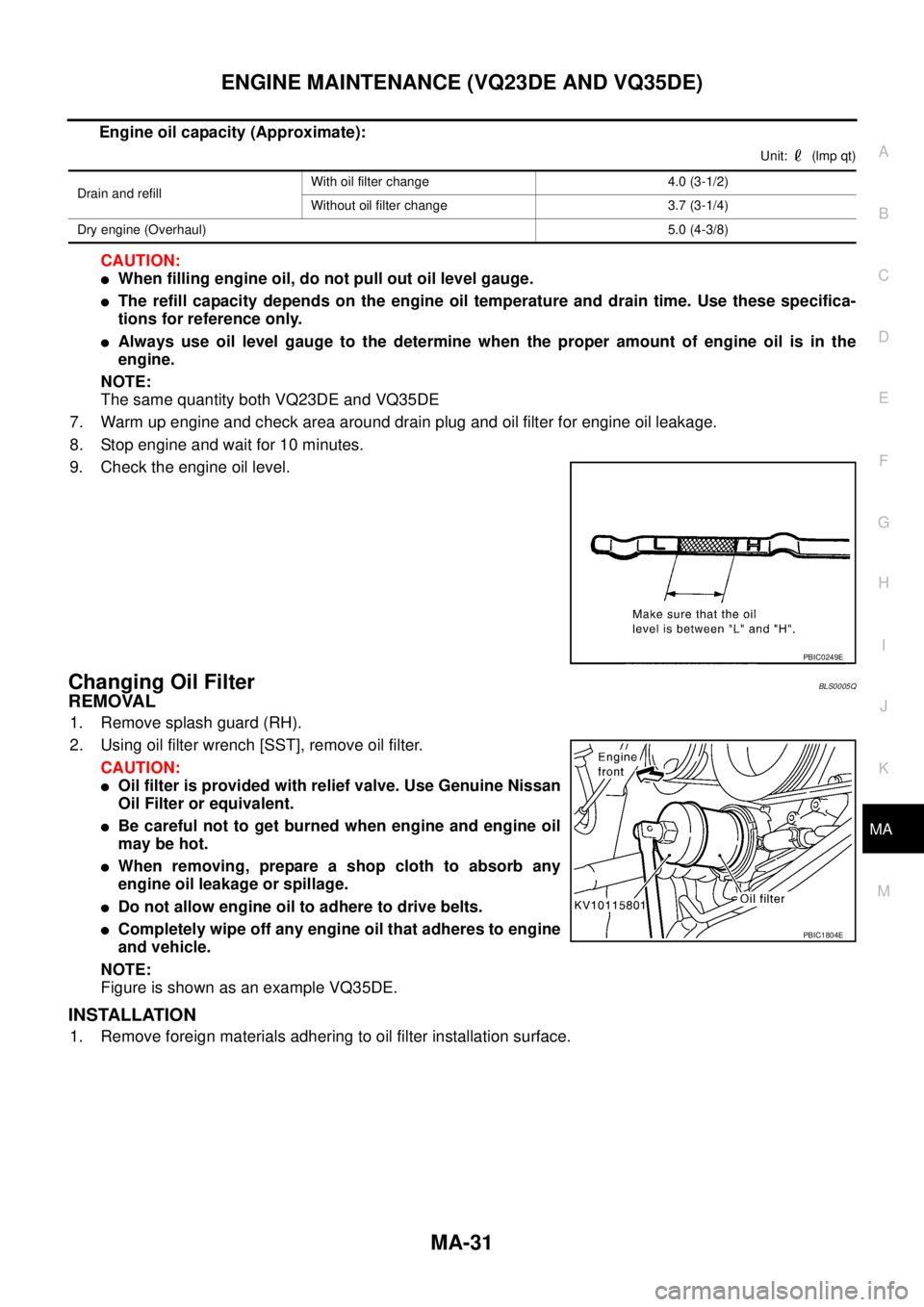
9. Check the engine oil level.
Changing Oil FilterBLS0005Q
REMOVAL
1. Remove splash guard (RH).
2. Using oil filter wrench [SST], remove oil filter.
CAUTION:
�Oil filter is provided with relief valve. Use Genuine Nissan
Oil Filter or equivalent.
�Be careful not to get burned when engine and engine oil
may be hot.
�When removing, prepare a shop cloth to absorb any
engine oil leakage or spillage.
�Do not allow engine oil to adhere to drive belts.
�Completely wipe off any engine oil that adheres to engine
and vehicle.
NOTE:
Figure is shown as an example VQ35DE.
INSTALLATION
1. Remove foreign materials adhering to oil filter installation surface.
Drain and refill With oil filter change 4.0 (3-1/2)
Without oil filter change 3.7 (3-1/4)
Dry engine (Overhaul)5.0 (4-3/8)
PBIC0249E
PBIC1804E
Page 3010 of 3502
MA-32
ENGINE MAINTENANCE (VQ23DE AND VQ35DE)
2. Apply engine oil to the oil seal contact surface of new oil filter.
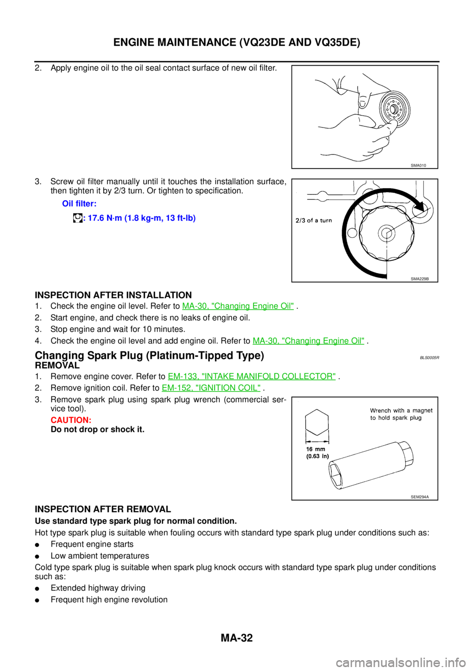
3. Screw oil filter manually until it touches the installation surface,
then tighten it by 2/3 turn. Or tighten to specification.
INSPECTION AFTER INSTALLATION
1. Check the engine oil level. Refer to MA-30, "Changing Engine Oil" .
2. Start engine, and check there is no leaks of engine oil.
3. Stop engine and wait for 10 minutes.
4. Check the engine oil level and add engine oil. Refer to MA-30, "
Changing Engine Oil" .
Changing Spark Plug (Platinum-Tipped Type)BLS0005R
REMOVAL
1. Remove engine cover. Refer to EM-133, "INTAKE MANIFOLD COLLECTOR" .
2. Remove ignition coil. Refer to EM-152, "
IGNITION COIL" .
3. Remove spark plug using spark plug wrench (commercial ser-
vice tool).
CAUTION:
Do not drop or shock it.
INSPECTION AFTER REMOVAL
Use standard type spark plug for normal condition.
Hot type spark plug is suitable when fouling occurs with standard type spark plug under conditions such as:
�Frequent engine starts
�Low ambient temperatures
Cold type spark plug is suitable when spark plug knock occurs with standard type spark plug under conditions
such as:
�Extended highway driving
�Frequent high engine revolution
SMA010
Oil filter:
: 17.6 N·m (1.8 kg-m, 13 ft-lb)
SMA229B
SEM294A
Page 3020 of 3502
MA-42
CHASSIS AND BODY MAINTENANCE
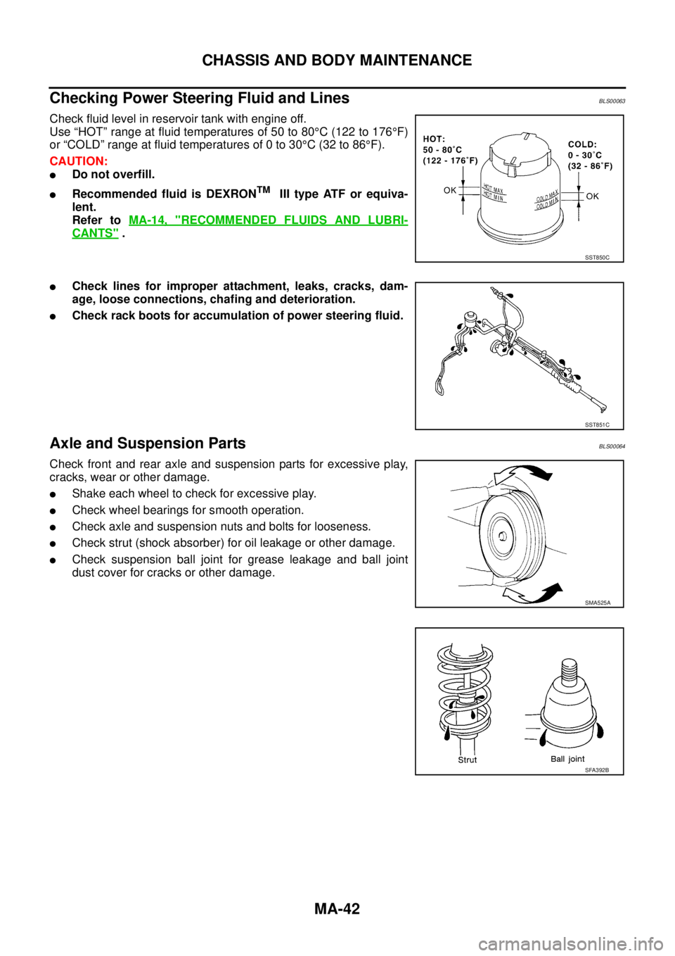
Checking Power Steering Fluid and LinesBLS00063
Check fluid level in reservoir tank with engine off.
Use “HOT” range at fluid temperatures of 50 to 80°C (122 to 176°F)
or “COLD” range at fluid temperatures of 0 to 30°C (32 to 86°F).
CAUTION:
�Do not overfill.
�Recommended fluid is DEXRONTM III type ATF or equiva-
lent.
Refer to MA-14, "
RECOMMENDED FLUIDS AND LUBRI-
CANTS" .
�Check lines for improper attachment, leaks, cracks, dam-
age, loose connections, chafing and deterioration.
�Check rack boots for accumulation of power steering fluid.
Axle and Suspension PartsBLS00064
Check front and rear axle and suspension parts for excessive play,
cracks, wear or other damage.
�Shake each wheel to check for excessive play.
�Check wheel bearings for smooth operation.
�Check axle and suspension nuts and bolts for looseness.
�Check strut (shock absorber) for oil leakage or other damage.
�Check suspension ball joint for grease leakage and ball joint
dust cover for cracks or other damage.
SST850C
SST851C
SMA525A
SFA392B
Page 3024 of 3502
MA-46
SERVICE DATA AND SPECIFICATIONS (SDS)
SERVICE DATA AND SPECIFICATIONS (SDS)PFP:00030
Standard and LimitBLS00068
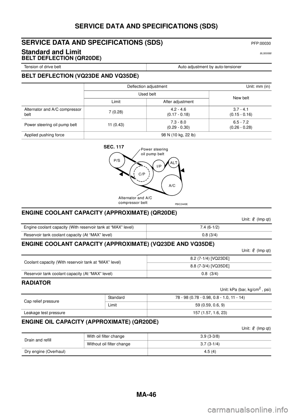
BELT DEFLECTION (QR20DE)
BELT DEFLECTION (VQ23DE AND VQ35DE)
ENGINE COOLANT CAPACITY (APPROXIMATE) (QR20DE)
Unit: (lmp qt)
ENGINE COOLANT CAPACITY (APPROXIMATE) (VQ23DE AND VQ35DE)
Unit: (lmp qt)
RADIATOR
Unit: kPa (bar, kg/cm2 , psi)
ENGINE OIL CAPACITY (APPROXIMATE) (QR20DE)
Unit: (lmp qt) Tension of drive belt Auto adjustment by auto-tensioner
Deflection adjustment Unit: mm (in)
Used belt
New belt
Limit After adjustment
Alternator and A/C compressor
belt7 (0.28)4.2 - 4.6
(0.17 - 0.18)3.7 - 4.1
(0.15 - 0.16)
Power steering oil pump belt 11 (0.43)7.3 - 8.0
(0.29 - 0.30)6.5 - 7.2
(0.26 - 0.28)
Applied pushing force 98 N (10 kg, 22 lb)
PBIC2449E
Engine coolant capacity (With reservoir tank at “MAX” level) 7.4 (6-1/2)
Reservoir tank coolant capacity (At “MAX” level) 0.8 (3/4)
Coolant capacity (With reservoir tank at “MAX” level)8.2 (7-1/4) [VQ23DE]
8.8 (7-3/4) [VQ35DE]
Reservoir tank coolant capacity (At “MAX” level) 0.8 (3/4)
Cap relief pressureStandard 78 - 98 (0.78 - 0.98, 0.8 - 1.0, 11 - 14)
Limit 59 (0.59, 0.6, 9)
Leakage test pressure 157 (1.57, 1.6, 23)
Drain and refillWith oil filter change 3.9 (3-3/8)
Without oil filter change 3.7 (3-1/4)
Dry engine (Overhaul)4.5 (4)
Page 3025 of 3502
SERVICE DATA AND SPECIFICATIONS (SDS)
MA-47
C
D
E
F
G
H
I
J
K
MA
B
MA
ENGINE OIL CAPACITY (APPROXIMATE) (VQ23DE AND VQ35DE)
Unit: (lmp qt)
SPARK PLUG (PLATINUM-TIPPED TYPE) (QR20DE, VQ23DE AND VQ35DE)
WHEEL BALANCE
Drain and refill With oil filter change 4.0 (3-1/2)
Without oil filter change 3.7 (3-1/4)
Dry engine (Overhaul)5.0 (4-3/8)
MakeNGK
Standard typePLFR5A-11
Hot typePLFR4A-11
Cold typePLFR6A-11
Gap (nominal)1.1 mm (0.043 in)
Maximum allowable unbalanceDynamic (At rim flange) Less than 10 g (0.35 oz) (one side)
Static (At rim flange) Less than 20 g (0.70 oz)
Page 3051 of 3502
IPDM E/R (INTELLIGENT POWER DISTRIBUTION MODULE ENGINE ROOM)
PG-17
C
D
E
F
G
H
I
J
L
MA
B
PG
IPDM E/R (INTELLIGENT POWER DISTRIBUTION MODULE ENGINE ROOM)
PFP:284B7
System DescriptionBKS0024N
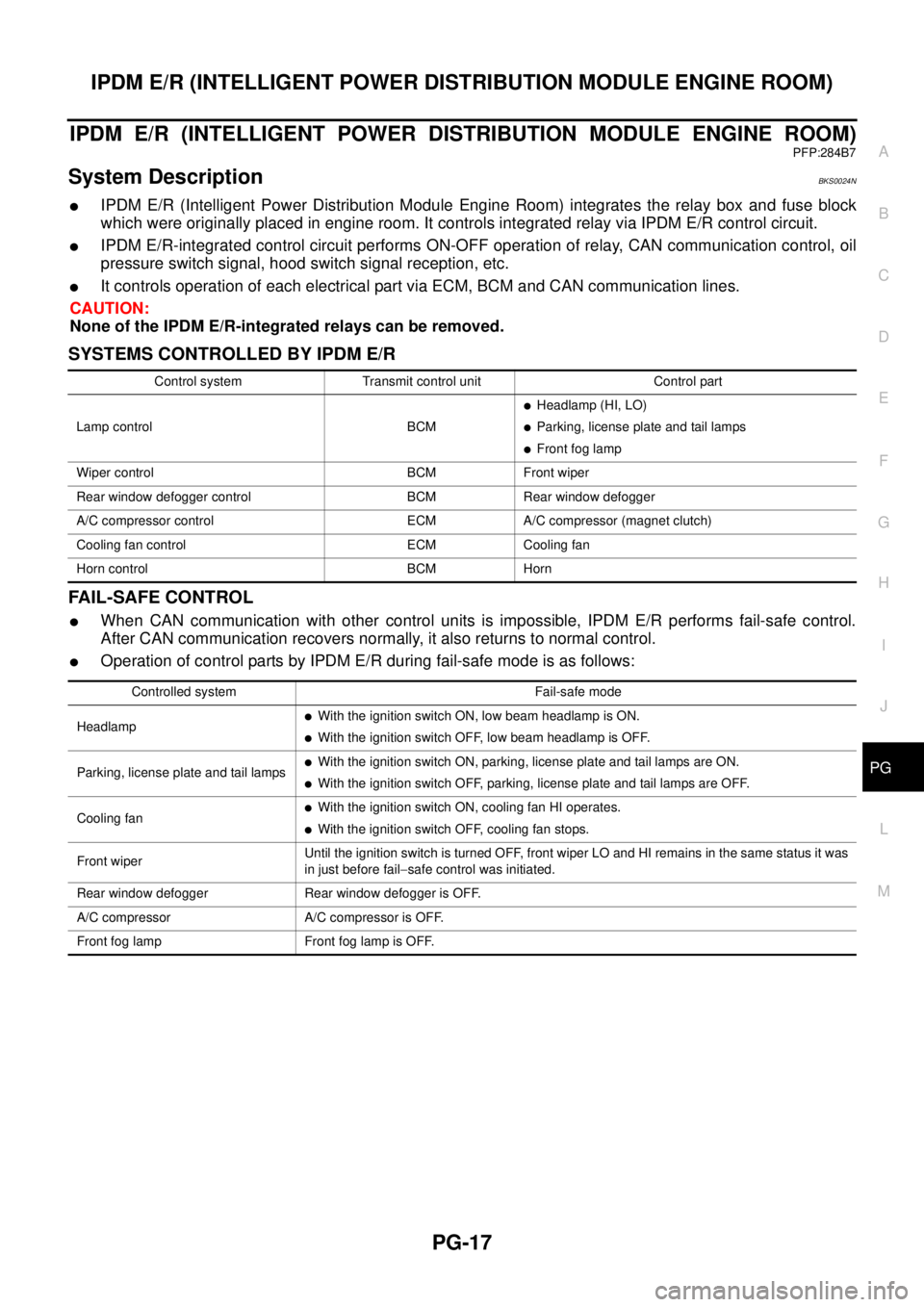
�IPDM E/R (Intelligent Power Distribution Module Engine Room) integrates the relay box and fuse block
which were originally placed in engine room. It controls integrated relay via IPDM E/R control circuit.
�IPDM E/R-integrated control circuit performs ON-OFF operation of relay, CAN communication control, oil
pressure switch signal, hood switch signal reception, etc.
�It controls operation of each electrical part via ECM, BCM and CAN communication lines.
CAUTION:
None of the IPDM E/R-integrated relays can be removed.
SYSTEMS CONTROLLED BY IPDM E/R
FAIL-SAFE CONTROL
�When CAN communication with other control units is impossible, IPDM E/R performs fail-safe control.
After CAN communication recovers normally, it also returns to normal control.
�Operation of control parts by IPDM E/R during fail-safe mode is as follows:
Control system Transmit control unit Control part
Lamp control BCM
�Headlamp (HI, LO)
�Parking, license plate and tail lamps
�Front fog lamp
Wiper control BCM Front wiper
Rear window defogger control BCM Rear window defogger
A/C compressor control ECM A/C compressor (magnet clutch)
Cooling fan control ECM Cooling fan
Horn control BCM Horn
Controlled system Fail-safe mode
Headlamp
�With the ignition switch ON, low beam headlamp is ON.
�With the ignition switch OFF, low beam headlamp is OFF.
Parking, license plate and tail lamps
�With the ignition switch ON, parking, license plate and tail lamps are ON.
�With the ignition switch OFF, parking, license plate and tail lamps are OFF.
Cooling fan
�With the ignition switch ON, cooling fan HI operates.
�With the ignition switch OFF, cooling fan stops.
Front wiperUntil the ignition switch is turned OFF, front wiper LO and HI remains in the same status it was
in just before fail−safe control was initiated.
Rear window defogger Rear window defogger is OFF.
A/C compressor A/C compressor is OFF.
Front fog lamp Front fog lamp is OFF.