2003 NISSAN TEANA service indicator
[x] Cancel search: service indicatorPage 2576 of 3502
IDX-2
ALPHABETICAL INDEX
Numerics
3rd position switch ............................. AT-161
, AT-210
A
A/C air flow ...................................................... ATC-31
A/C component layout ..................................... ATC-20
A/C compressor clutch removal and installation ...........
ATC-136
A/C compressor mounting ............................. ATC-134
A/C compressor precaution ............................. ATC-11
A/C compressor special service tool ................ ATC-15
A/C control operation (auto A/C) ...................... ATC-29
A/C diagnostic work flow (auto A/C) ................ ATC-94
A/C evaporator ............................................... ATC-144
A/C HFC134a (R134a) system precaution ........ ATC-5
A/C HFC134a (R134a) system service procedure .......
ATC-131
A/C HFC134a (R134a) system service tools ... ATC-16
A/C HFC134a system service equipment precaution ...
ATC-12
A/C lubricant (R134a) ...................................... ATC-21
A/C lubrication oil ........................................... ATC-150
A/C operational check ...................................... ATC-54
A/C self-diagnoses (auto A/C) .......... ATC-46, ATC-94
A/C service data specification ........................ ATC-150
A/C system description (auto A/C) ................... ATC-24
A/C, A - Wiring diagram ................................... ATC-39
A/T fluid checking .................................. AT-14, MA-35
A/T fluid replacement ............................. AT-15, MA-36
A/T IND - Wiring diagram .................................... DI-48
A/T shift control system ................................... AT-213
A/T shift lock system ........................................ AT-216
A/T shift lock system - Wiring diagram ............ AT-217
A/T trouble diagnoses ........................................ AT-34
Accelerator control system ............................... ACC-3
Accelerator pedal position (APP) sensor ........ EC-251,
EC-258
, EC-272, EC-631, EC-638, EC-652
Accelerator pedal released position learning .... EC-47,
EC-389
AFS ..................................................................... LT-75
AFS - Wiring diagram ......................................... LT-79
Air bag .............................................................. SRS-3
Air bag disposal .............................................. SRS-48
Air bag precautions ........................................... SRS-3
Air cleaner and air duct(QR20DE) .................... EM-17
Air cleaner and air duct(VQ23DE and VQ35DE) ..........
EM-131
Air cleaner filter replacement(QR20DE) ........... MA-20
Air cleaner filter replacement(VQ23DE and VQ35DE) .
MA-30
Air cleaner filter(QR20DE) ................................ EM-17
Air cleaner filter(VQ23DE and VQ35DE) ........ EM-132
Air conditioner cut control .................... EC-25, EC-362
Air flow meter - See Mass air flow sensor ...... EC-124,
EC-466
Air mix. door motor ......................... ATC-66, ATC-124
Ambient sensor ............................... ATC-96, ATC-109
Angular tightening application(QR20DE) ............ EM-6
Angular tightening application(VQ23DE and VQ35DE)
EM-120
Antenna ............................................................. AV-38
APPS1 - Wiring diagram ................... EC-253, EC-633
APPS2 - Wiring diagram ................... EC-260, EC-640
APPS3 - Wiring diagram ................... EC-274, EC-654
ASC/BS - Wiring diagram ................................ EC-605
ASC/SW - Wiring diagram ............................... EC-597
ASCBOF - Wiring diagram ............................... EC-661
ASCD ............................................................... EC-363
ASCD (automatic speed control device) ........... ACS-2
ASCD brake switch ........................... EC-602, EC-660
ASCD indicator lamp ....................................... EC-667
ASCD steering switch ...................................... EC-595
ASCIND - Wiring diagram ................................ EC-668
AT indicator lamp ................................................ DI-48
Audio ........................................................ AV-4, AV-18
AUDIO - Wiring diagram .......................... AV-7, AV-21
Auto air conditioner - Wiring diagram ............. ATC-39
Auto amp ...................................................... ATC-108
Auto anti-dazzling inside mirror ....................... GW-80
Automatic amplifier ........... ATC-44, ATC-56, ATC-108
AV communication line .......................... AV-49, AV-73
Axle ................................................................... MA-42
B
BA/FTS - Wiring diagram ................................. AT-111
BACK/L - Wiring diagram ................................. LT-193
Back-up lamp ................................................... LT-193
Basic inspection .................................. EC-40, EC-381
Battery ................................................................. SC-4
BCM (Body control module) .............................. BCS-3
Blower motor ................................... ATC-72, ATC-115
Blower unit .................................................... ATC-113
Boring/horning cylinder block(QR20DE) ......... EM-104
Boring/horning cylinder block(VQ23DE and VQ35DE) .
EM-250
Brake fluid level ................................................ MA-40
Brake hydraulic line ........................................... BR-11
Brake inspection ............................................... MA-41
Brake lines and cables inspection .................... MA-40
Brake pedal .......................................................... BR-6
Brake switch ......... EC-245, EC-602, EC-626, EC-660
BRK/SW - Wiring diagram ................ EC-247, EC-627
Bulb specifications ........................................... LT-261
Bumper, front ...................................................... EI-14
Bumper, rear ....................................................... EI-17
C
Camshaft inspection(QR20DE) ........................ EM-44
Camshaft inspection(VQ23DE and VQ35DE) EM-194
Camshaft position sensor (PHASE) .. EC-176, EC-524
Camshaft(QR20DE) .......................................... EM-41
Camshaft(VQ23DE and VQ35DE) .................. EM-192
CAN - Wiring diagram ......... EC-114, EC-459, AT-134,
CVT-54
Page 2577 of 3502
IDX-3
A
C
D
E
F
G
H
I
J
K
L B
IDX
ALPHABETICAL INDEX
CAN (Controller Area Network) . BL-23, BL-48, BL-77,
GW-56
, SE-16
CAN communication EC-113, EC-458, AT-27, CVT-19,
CVT-53
, BL-23, BL-48, BL-77, GW-56, SE-16, WW-9
Canister-See EVAP canister ............... EC-29, EC-369
CHARGE - Wiring diagram ................................ SC-28
Charging system ................................................ SC-27
Chassis and body maintenance ........................ MA-35
CHIME - Wiring diagram ..................................... DI-60
CIGAR - Wiring diagram .................................. WW-60
Cigarette lighter ............................................... WW-60
Circuit breaker ................................................... PG-16
Closed loop control .............................. EC-22, EC-359
Collision diagnosis ........................................... SRS-55
Combination meter ............................................... DI-4
COMM - Wiring diagram ........................ AV-49, AV-73
Component Location (auto A/C) ...................... ATC-36
Compression pressure(QR20DE) ...................... EM-65
Compression pressure(VQ23DE and VQ35DE) ...........
EM-210
Compressor clutch removal and installation .. ATC-136
Compressor special service tool ...................... ATC-15
Condenser ..................................................... ATC-142
Connecting rod bearing clearance(QR20DE) .. EM-105
Connecting rod bearing clearance(VQ23DE and
VQ35DE) ......................................................... EM-251
Connecting rod bushing clearance(QR20DE) . EM-101
Connecting rod bushing clearance(VQ23DE and
VQ35DE) ......................................................... EM-247
Connecting rod(QR20DE) ............................... EM-101
Connecting rod(VQ23DE and VQ35DE) ......... EM-247
CONSULT-II for engine ....................... EC-80, EC-425
CONSULT-II Reference value (CVT) .............. CVT-43
Control units (terminal arrangement) ................. PG-74
Control valve (CVT) ......................................... CVT-23
Controller Area Network (CAN) . BL-23, BL-48, BL-77,
GW-56
, SE-16
Converter housing installation ............ AT-244, AT-355
COOL/F - Wiring diagram .................. EC-222, EC-579
Coolant mixture ratio ......................................... MA-15
Coolant replacement(QR20DE) ......................... MA-16
Coolant replacementVQ35DE ........................... MA-25
Cooling circuit (engine)(QR20DE) ....................... CO-8
Cooling circuit (engine)(VQ32DE and VQ35DE) CO-32
Cooling fan control ........................................... EC-575
Cooling fan motor ............................................ EC-575
Cooling fan relay .............................................. EC-575
Cooling fan(QR20DE) ........................................ CO-20
Cooling fan(VQ23DE and VQ35DE) .................. CO-44
Cowl top ............................................................... EI-21
Cowl top cover ..................................................... EI-21
Crankcase ventilation system - See Positive crankcase
ventilation ............................................ EC-30
, EC-370
Crankshaft position sensor (POS) ..... EC-169, EC-517
Crankshaft(QR20DE) ...................................... EM-104
Crankshaft(VQ23DE and VQ35DE) ................ EM-251
Crash zone sensor .......................................... SRS-44
CVT air breather hose ................................... CVT-186
CVT control system ......................................... CVT-16
CVT cross-sectional view ................................ CVT-15
CVT Electrical parts location ............................ CVT-30
CVT fluid checking ................ CVT-13, CVT-32, MA-36
CVT Fluid Cooler ........................................... CVT-189
CVT fluid replacement ........................ CVT-14, MA-38
CVT fluid temparature sensor .......................... CVT-69
CVT hydraulic control system .......................... CVT-17
CVT indicator ...................................................... DI-52
CVT self-diagnoses ......................................... CVT-47
CVT shift lock system .................................... CVT-180
CVT trouble diagnoses .................................... CVT-24
CVTIND - Wiring diagram ................................... DI-52
Cylinder block boring(QR20DE) ..................... EM-104
Cylinder block(QR20DE) .................................. EM-81
Cylinder block(VQ23DE and VQ35DE) .......... EM-228
Cylinder head bolt tightening(QR20DE) ........... EM-68
Cylinder head bolt tightening(VQ23DE and VQ35DE) .
EM-213
Cylinder head(QR20DE) ................................... EM-65
Cylinder head(VQ23DE and VQ35DE) ........... EM-210
D
D/LOCK - Wiring diagram .................................. BL-25
Diagnosis sensor unit ..................................... SRS-47
Diagnostic trouble code (DTC) for OBD system EC-10,
EC-34
, EC-347, EC-375
Diagnostic trouble code (DTC) inspection priority chart
EC-58
, EC-400, CVT-24
Differentil side oil seal .................................... CVT-187
Display and amp.assembly ............... ATC-44, ATC-56
Display Control Unit ........................................... AV-61
Display Unit ........................................................ AV-41
Door glass ........................................... GW-46, GW-50
Door glass Fitting Adjustment(Front) ................ GW-49
Door glass Fitting Adjustment(Rear) ................. GW-53
Door lock .......................................................... BL-123
Door mirror .......................................... GW-74, GW-77
Door trim ............................................................. EI-35
Door, front ........................................... BL-119, GW-46
Door, rear ............................................ BL-119, GW-50
Drive belt inspection(QR20DE) ......................... MA-16
Drive belt inspection(VQ23DE and VQ35DE) ... MA-24
Drive belt(QR20DE) .......................................... EM-14
Drive belt(VQ23DE and VQ35DE) .................. EM-128
Drive shaft ......................................................... MA-43
Driver air bag .................................................. SRS-35
Dropping resistor (A/T) .................................... AT-132
Duct and grilles .............................................. ATC-126
E
ECM input/output signal ....................... EC-72
, EC-415
ECM power supply EC-106, EC-193, EC-451, EC-541
ECM/PW - Wiring diagram ................. EC-194, EC-542
ECTS - Wiring diagram ...................... EC-133, EC-476
Electric sunroof .................................................. RF-10
Electric throttle control actuator ........ EC-197, EC-200,
EC-213
, EC-552, EC-555
Page 2579 of 3502
IDX-5
A
C
D
E
F
G
H
I
J
K
L B
IDX
ALPHABETICAL INDEX
Heated oxygen sensor 1 (bank 2) .... EC-486, EC-496,
EC-696
Heated oxygen sensor 1 heater ...................... EC-308
Heated oxygen sensor 1 heater (bank 1) ........ EC-706
Heated oxygen sensor 1 heater (bank 2) ........ EC-706
Heated oxygen sensor 2 .................................. EC-313
Heated oxygen sensor 2 (bank 1) ..... EC-714, EC-723
Heated oxygen sensor 2 (bank 2) ..... EC-714, EC-723
Heated oxygen sensor 2 heater ...................... EC-319
Heated seat ....................................................... SE-61
Heater and cooling unit (Heater core) ........... ATC-119
HFC134a (R134a) system precaution ............... ATC-5
HFC134a (R134a) system service procedure ATC-131
HFC134a (R134a) system service tools .......... ATC-16
HFC134a system service equipment precaution ..........
ATC-12
HLC - Wiring diagram ...................................... WW-43
HO2S1 - Wiring diaram ..................... EC-145, EC-152
Horn ................................................................. WW-62
HORN - Wiring diagram ................................... WW-62
How to erase DTC for OBD system ..... EC-35, EC-376
HSEAT - Wiring diagram ................................... SE-70
I
IATSEN - Wiring diagram .................. EC-325
, EC-731
Idle air volume learning ....................... EC-47, EC-389
Idle speed .............................. EC-40, EC-381, EC-387
Ignition coil ......................................... EC-329, EC-735
Ignition coil(QR20DE) ........................................ EM-31
Ignition coil(VQ23DE and VQ35DE) ................ EM-152
Ignition control system ....................... EC-329, EC-735
Ignition timing ........................ EC-40, EC-381, EC-387
IGNSYS - Wiring diagram .................. EC-330, EC-736
In vehicle sensor ............................. ATC-99, ATC-110
INF/D - Wring diagram ........................... AV-43, AV-65
INJECT - Wiring diagram ................... EC-290, EC-685
Injector ............................................... EC-289, EC-684
Input/Output signal of TCM .............................. CVT-19
Instrument panel .................................................. IP-10
INT/L - Wiring diagram ..................................... LT-217
Intake air temperature sensor ............ EC-324, EC-730
Intake door control linkage adjustment ............ ATC-71
Intake door motor ........................... ATC-69, ATC-117
Intake manifold collector(VQ23DE and VQ35DE) ........
EM-133
Intake manifold(QR20DE) ................................. EM-19
Intake manifold(VQ23DE and VQ35DE) ......... EM-138
Intake sensor ................................ ATC-105, ATC-112
Intake valve timing control ............................... EC-116
Intake valve timing control (Bank 1) ................ EC-461
Intake valve timing control (Bank 2) ................ EC-461
Intake valve timing control solenoid valve (Bank 1) ......
EC-545
Intake valve timing control solenoid valve (Bank 2) ......
EC-545
Interior ................................................................. EI-38
Interior lamp ........................................ LT-217, LT-219
IPDM (Intelligent power distribution module engine room) ................................................................. PG-17
IVC - Wiring diagram ....................................... EC-119
IVCB1 - Wiring diagram ................................... EC-546
IVCB2 - Wiring diagram ................................... EC-548
K
Knock sensor (KS) ............................. EC-164
, EC-512
KS - Wiring diagram ........................... EC-165, EC-513
L
L/USSV - Wiring diagram ............................... CVT-148
LAN system circuit ........................................... ATC-59
LCD display ....................................................... AV-61
Line pressure and secondary pressure control CVT-20
Line pressure solenoid valve .......... CVT-97, CVT-102
Line pressure test (A/T) ..................................... AT-46
Liquid gasket application(QR20DE) ........... EM-6, LU-3
Liquid gasket application(VQ23DE and VQ35DE) ........
EM-120
, LU-15, CO-3, CO-27
Location of electrical units ................................. PG-67
Lock-up and select control ............................... CVT-21
Lock-up select solenoid valve ........................ CVT-147
LPSV - Wiring diagram ...................... AT-127, CVT-98
Lubricant (R134a) A/C ..................................... ATC-21
Lubricants ......................................................... MA-14
Lubrication circuit (engine)(QR20DE) .................. LU-5
Lubrication circuit (engine)(VQ23DE and VQ35DE) .....
LU-17
Lubrication oil A/C .......................................... ATC-150
M
MAFS - Wiring diagram ..................... EC-126
, EC-468
Magnet clutch ................................. ATC-78, ATC-136
MAIN - Wiring diagram ........ EC-106, EC-451, AT-158
Maintenance (engine)(VQ23DE and VQ35DE) MA-24
Malfunction indicator (MI) .................... EC-36, EC-377
Mass air flow sensor (MAFS) ............. EC-124, EC-466
Meter ..................................................................... DI-4
METER - Wiring diagram .................................... DI-10
MIL data link connectors circuit ......... EC-344, EC-763
MIL/DL - Wiring diagram .................... EC-344, EC-763
Mirror, door ......................................... GW-74, GW-77
Mirror, out side .................................... GW-74, GW-77
MMSW - Wiring diagram ................................ CVT-114
Mode door control linkage adjustment ............. ATC-65
Mode door motor ............................ ATC-63, ATC-123
Molding - See Exterior EI-25, EI-27, EI-28, EI-29, EI-30
Mud guard - See Exterior .................................... EI-24
Multiport fuel injection (MFI) system .... EC-21, EC-358
Multiport fuel injection precautions ....................... GI-6
N
NATS - Wiring diagram .................................... BL-143
NATS (Nissan anti-theft system) precautions ....... GI-3
NONDTC - Wiring diagram .............. AT-168, CVT-160
Page 2689 of 3502
LT-1
LIGHTING SYSTEM
K ELECTRICAL
CONTENTS
C
D
E
F
G
H
I
J
L
M
SECTION LT
A
B
LT
LIGHTING SYSTEM
PRECAUTIONS .......................................................... 5
Precautions for Supplemental Restraint System
(SRS) “AIR BAG” and “SEAT BELT PRE-TEN-
SIONER” .................................................................. 5
General Precautions for Service Operations ............ 5
HEADLAMP - XENON TYPE - ................................... 6
Component Parts and Harness Connector Location ..... 6
System Description .................................................. 6
OUTLINE ............................................................... 6
LOW BEAM OPERATION ..................................... 7
HIGH BEAM OPERATION .................................... 7
FLASH-TO-PASS OPERATION ............................ 8
COMBINATION SWITCH READING FUNCTION ..... 8
EXTERIOR LAMP BATTERY SAVER CONTROL ..... 8
AUTO LIGHT OPERATION ................................... 8
XENON HEADLAMP ............................................. 9
CAN Communication System Description ................ 9
CAN Communication Unit ........................................ 9
Schematic .............................................................. 10
Wiring Diagram — H/LAMP — ................................ 11
Terminals and Reference Values for BCM ............. 15
Terminals and Reference Values for IPDM E/R ..... 17
How to Perform Trouble Diagnosis ........................ 17
Preliminary Check .................................................. 17
CHECK POWER SUPPLY AND GROUND CIR-
CUIT .................................................................... 17
CONSULT-II Functions (BCM) ............................... 18
CONSULT-II BASIC OPERATION ....................... 18
WORK SUPPORT ............................................... 19
DATA MONITOR ................................................. 19
ACTIVE TEST ..................................................... 20
CONSULT-II Functions (IPDM E/R) ....................... 20
CONSULT-II OPERATION .................................. 20
DATA MONITOR ................................................. 21
ACTIVE TEST ..................................................... 21
Headlamp Do Not Change To High (Both Sides) ... 22
Headlamp Does Not Change To High (One Side) ... 25
High Beam Indicator Does Not Illuminate .............. 26
Headlamp Do Not Illuminate (Both Sides) ............. 27
Headlamp Does Not Illuminate (One Side) ............ 29Headlamps Do Not Change to Low (Both Sides) ... 30
Headlamps Do Not Turn OFF ................................. 31
General Information for Xenon Headlamp Trouble
Diagnosis ................................................................ 32
Caution: .................................................................. 32
Xenon Headlamp Trouble Diagnosis ...................... 32
Aiming Adjustment .................................................. 33
PREPARATION BEFORE ADJUSTING .............. 33
LOW BEAM AND HIGH BEAM ........................... 33
ADJUSTMENT USING AN ADJUSTMENT
SCREEN (LIGHT/DARK BORDERLINE) ............ 34
Bulb Replacement .................................................. 35
HEADLAMP HIGH/LOW BEAM .......................... 35
BENDING LAMP ................................................. 35
PARKING LAMP .................................................. 35
FRONT TURN SIGNAL LAMP ............................ 35
Removal and Installation ........................................ 36
REMOVAL ........................................................... 36
INSTALLATION ................................................... 36
Disassembly and Assembly .................................... 37
DISASSEMBLY ................................................... 37
ASSEMBLY ......................................................... 37
HEADLAMP - HALOGEN TYPE - ............................ 38
Component Parts and Harness Connector Location ... 38
System Description ................................................. 38
OUTLINE ............................................................. 38
LOW BEAM OPERATION ................................... 39
HIGH BEAM OPERATION .................................. 39
FLASH-TO-PASS OPERATION .......................... 40
COMBINATION SWITCH READING FUNCTION ... 40
EXTERIOR LAMP BATTERY SAVER CONTROL ... 40
AUTO LIGHT OPERATION ................................. 40
CAN Communication System Description .............. 40
CAN Communication Unit ....................................... 40
Schematic ............................................................... 41
Wiring Diagram — H/LAMP — ............................... 42
Terminals and Reference Values for BCM .............. 46
Terminals and Reference Values for IPDM E/R ...... 48
How to Perform Trouble Diagnosis ......................... 48
Preliminary Check .................................................. 48
Page 3219 of 3502

SC-1
STARTING & CHARGING SYSTEM
K ELECTRICAL
CONTENTS
C
D
E
F
G
H
I
J
L
M
SECTION SC
A
B
SC
STARTING & CHARGING SYSTEM
PRECAUTIONS .......................................................... 2
Precautions for Supplemental Restraint System
(SRS) “AIR BAG” and “SEAT BELT PRE-TEN-
SIONER” .................................................................. 2
PREPARATION ........................................................... 3
Commercial Service Tools ........................................ 3
BATTERY .................................................................... 4
How to Handle Battery ............................................. 4
METHODS OF PREVENTING OVER-DIS-
CHARGE ............................................................... 4
CHECKING ELECTROLYTE LEVEL .................... 5
SPECIFIC GRAVITY CHECK ............................... 5
Battery Test and Charging Chart .............................. 7
CHART I ................................................................ 7
CHART II ............................................................... 8
A: SLOW CHARGE ............................................... 9
B: STANDARD CHARGE .................................... 10
C: QUICK CHARGE ............................................ 12
Removal and Installation ........................................ 13
REMOVAL ........................................................... 13
INSTALLATION ................................................... 13
STARTING SYSTEM ................................................ 14
System Description ................................................ 14
Wiring Diagram — START — ................................. 15
A/T MODELS ...................................................... 15
CVT MODELS ..................................................... 16
Trouble Diagnosis .................................................. 17
Removal and Installation ........................................ 18VQ23DE AND VQ35DE MODELS ...................... 18
REMOVAL ........................................................... 18
INSTALLATION ................................................... 18
QR20DE MODELS .............................................. 19
REMOVAL ........................................................... 19
INSTALLATION ................................................... 19
Disassembly and Assembly .................................... 20
DISASSEMBLY ................................................... 20
INSPECTION ...................................................... 23
ASSEMBLY ......................................................... 26
CHARGING SYSTEM ............................................... 27
System Description ................................................. 27
MALFUNCTION INDICATOR .............................. 27
Wiring Diagram — CHARGE — ............................. 28
Trouble Diagnosis ................................................... 29
WITH IC REGULATOR ........................................ 29
Removal and Installation ........................................ 30
VQ23DE AND VQ35DE MODELS ...................... 30
QR20DE MODELS .............................................. 32
Disassembly and Assembly .................................... 33
DISASSEMBLY ................................................... 34
INSPECTION ...................................................... 35
ASSEMBLY ......................................................... 36
SERVICE DATA AND SPECIFICATIONS (SDS) ...... 38
Battery .................................................................... 38
Starter ..................................................................... 38
Alternator ................................................................ 38
Page 3257 of 3502
SE-1
SEAT
I BODY
CONTENTS
C
D
E
F
G
H
J
K
L
M
SECTION SE
A
B
SE
SEAT
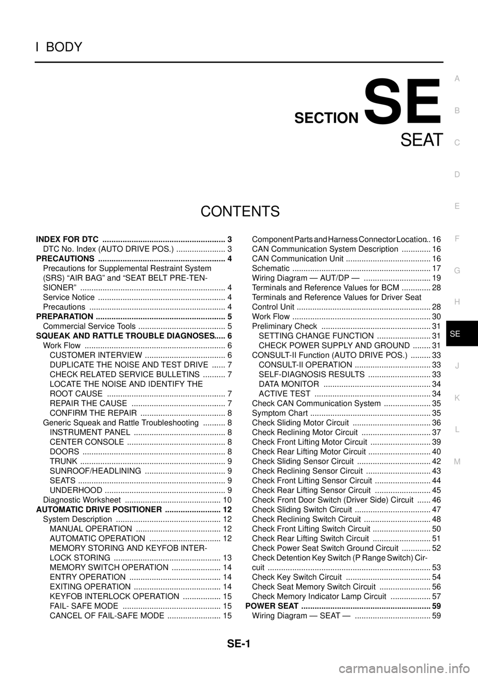
INDEX FOR DTC ........................................................ 3
DTC No. Index (AUTO DRIVE POS.) ....................... 3
PRECAUTIONS .......................................................... 4
Precautions for Supplemental Restraint System
(SRS) “AIR BAG” and “SEAT BELT PRE-TEN-
SIONER” .................................................................. 4
Service Notice .......................................................... 4
Precautions .............................................................. 4
PREPARATION ........................................................... 5
Commercial Service Tools ........................................ 5
SQUEAK AND RATTLE TROUBLE DIAGNOSES ..... 6
Work Flow ................................................................ 6
CUSTOMER INTERVIEW ..................................... 6
DUPLICATE THE NOISE AND TEST DRIVE ....... 7
CHECK RELATED SERVICE BULLETINS ........... 7
LOCATE THE NOISE AND IDENTIFY THE
ROOT CAUSE ...................................................... 7
REPAIR THE CAUSE ........................................... 7
CONFIRM THE REPAIR ....................................... 8
Generic Squeak and Rattle Troubleshooting ........... 8
INSTRUMENT PANEL .......................................... 8
CENTER CONSOLE ............................................. 8
DOORS ................................................................. 8
TRUNK .................................................................. 9
SUNROOF/HEADLINING ..................................... 9
SEATS ................................................................... 9
UNDERHOOD ....................................................... 9
Diagnostic Worksheet ............................................ 10
AUTOMATIC DRIVE POSITIONER .......................... 12
System Description ................................................ 12
MANUAL OPERATION ....................................... 12
AUTOMATIC OPERATION ................................. 12
MEMORY STORING AND KEYFOB INTER-
LOCK STORING ................................................. 13
MEMORY SWITCH OPERATION ....................... 14
ENTRY OPERATION .......................................... 14
EXITING OPERATION ........................................ 14
KEYFOB INTERLOCK OPERATION .................. 15
FAIL- SAFE MODE ............................................. 15
CANCEL OF FAIL-SAFE MODE ......................... 15Component Parts and Harness Connector Location ... 16
CAN Communication System Description .............. 16
CAN Communication Unit ....................................... 16
Schematic ............................................................... 17
Wiring Diagram — AUT/DP — ............................... 19
Terminals and Reference Values for BCM .............. 28
Terminals and Reference Values for Driver Seat
Control Unit ............................................................. 28
Work Flow ............................................................... 30
Preliminary Check .................................................. 31
SETTING CHANGE FUNCTION ......................... 31
CHECK POWER SUPPLY AND GROUND ......... 31
CONSULT-II Function (AUTO DRIVE POS.) .......... 33
CONSULT-II OPERATION ................................... 33
SELF-DIAGNOSIS RESULTS ............................. 33
DATA MONITOR ................................................. 34
ACTIVE TEST ..................................................... 34
Check CAN Communication System ...................... 35
Symptom Chart ....................................................... 35
Check Sliding Motor Circuit .................................... 36
Check Reclining Motor Circuit ................................ 37
Check Front Lifting Motor Circuit ............................ 39
Check Rear Lifting Motor Circuit ............................. 40
Check Sliding Sensor Circuit .................................. 42
Check Reclining Sensor Circuit .............................. 43
Check Front Lifting Sensor Circuit .......................... 44
Check Rear Lifting Sensor Circuit .......................... 45
Check Front Door Switch (Driver Side) Circuit ....... 46
Check Sliding Switch Circuit ................................... 47
Check Reclining Switch Circuit ............................... 48
Check Front Lifting Switch Circuit ........................... 50
Check Rear Lifting Switch Circuit ........................... 51
Check Power Seat Switch Ground Circuit .............. 52
Check Detention Key Switch (P Range Switch) Cir-
cuit .......................................................................... 53
Check Key Switch Circuit ....................................... 54
Check Seat Memory Switch Circuit ........................ 56
Check Memory Indicator Lamp Circuit ................... 57
POWER SEAT ........................................................... 59
Wiring Diagram — SEAT — ................................... 59
Page 3291 of 3502
AUTOMATIC DRIVE POSITIONER
SE-35
C
D
E
F
G
H
J
K
L
MA
B
SE
Check CAN Communication System BIS0012R
1. CHECK SELF-DIAGNOSTIC RESULT
CAUTION:
If CONSULT-II is used with no connection of CONSULT-II CONVERTER, malfunctions might be
detected in self-diagnosis depending on control unit which carry out CAN communication.
With CONSULT-II
1. Connect CONSULT-II, and turn ignition switch ON.
2. Touch “AUTO DRIVE POS” on “SELECT SYSTEM” screen.
3. Touch “SELF-DIAG RESULTS” on “SELECT DIAG MODE” screen.
4. Check display content in self-diagnostic results.
Displayed U1000?
Ye s > > G O T O LAN-49, "CAN System Specification Chart" .
No >> Inspection END.
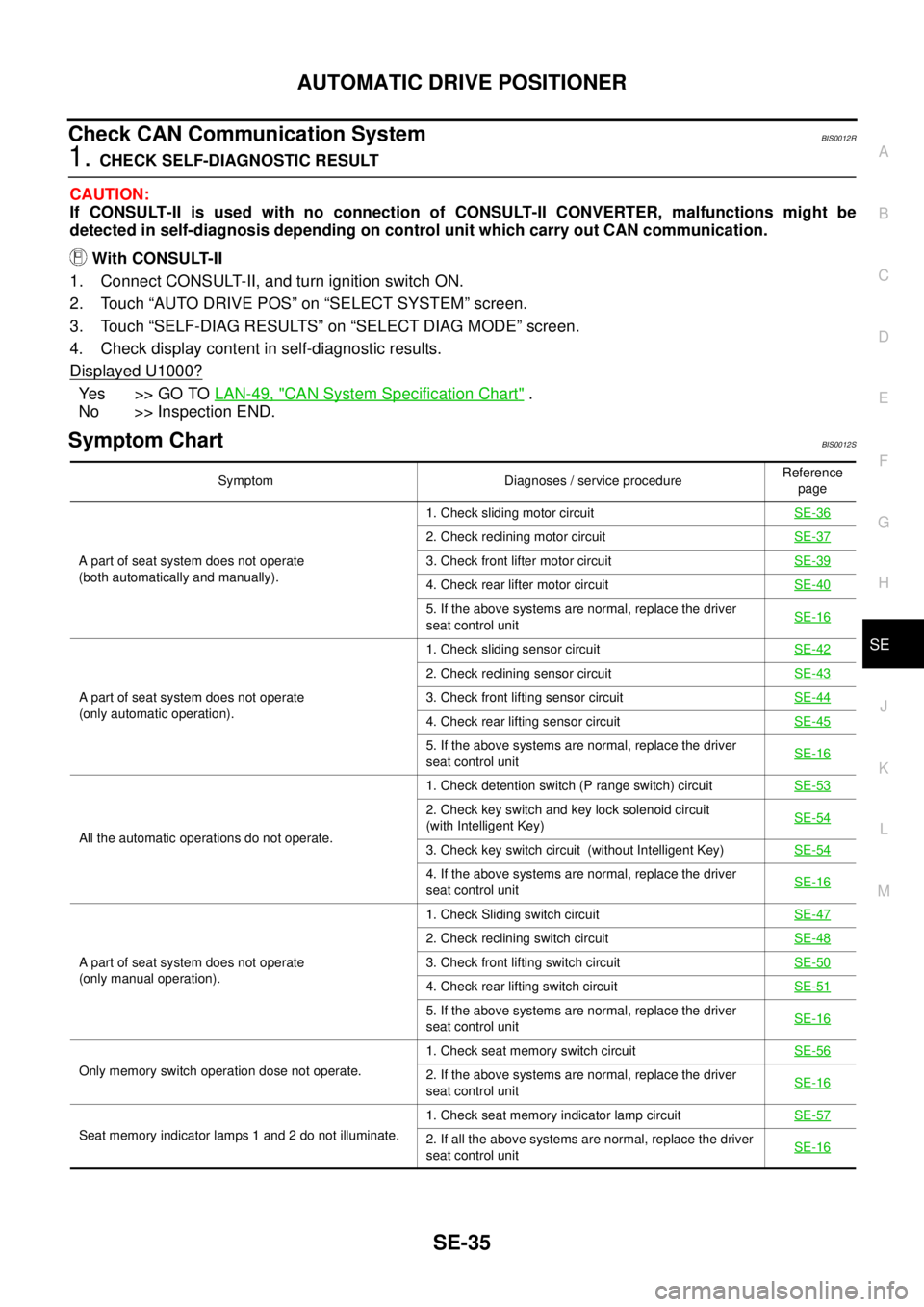
Symptom ChartBIS0012S
Symptom Diagnoses / service procedureReference
page
A part of seat system does not operate
(both automatically and manually).1. Check sliding motor circuit SE-36
2. Check reclining motor circuit SE-37
3. Check front lifter motor circuit SE-39
4. Check rear lifter motor circuit SE-40
5. If the above systems are normal, replace the driver
seat control unitSE-16
A part of seat system does not operate
(only automatic operation).1. Check sliding sensor circuit SE-42
2. Check reclining sensor circuit SE-43
3. Check front lifting sensor circuit SE-44
4. Check rear lifting sensor circuit SE-45
5. If the above systems are normal, replace the driver
seat control unitSE-16
All the automatic operations do not operate.1. Check detention switch (P range switch) circuit SE-53
2. Check key switch and key lock solenoid circuit
(with Intelligent Key)SE-54
3. Check key switch circuit (without Intelligent Key)SE-54
4. If the above systems are normal, replace the driver
seat control unitSE-16
A part of seat system does not operate
(only manual operation).1. Check Sliding switch circuit SE-47
2. Check reclining switch circuit SE-48
3. Check front lifting switch circuit SE-50
4. Check rear lifting switch circuit SE-51
5. If the above systems are normal, replace the driver
seat control unitSE-16
Only memory switch operation dose not operate.1. Check seat memory switch circuit SE-562. If the above systems are normal, replace the driver
seat control unitSE-16
Seat memory indicator lamps 1 and 2 do not illuminate.1. Check seat memory indicator lamp circuitSE-572. If all the above systems are normal, replace the driver
seat control unitSE-16
Page 3435 of 3502
ROAD WHEEL
WT-3
C
D
F
G
H
I
J
K
L
MA
B
WT
ROAD WHEELPFP:40300
InspectionBES0004H
ALUMINUM WHEEL
1. Check tyres for wear and improper inflation.
2. Check wheels for deformation, cracks and other damage. If deformed, remove wheel and check wheel
runout.
a. Remove tyre from aluminum wheel and mount on a tyre balance
machine.
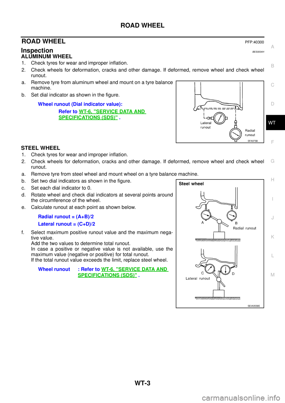
b. Set dial indicator as shown in the figure.
STEEL WHEEL
1. Check tyres for wear and improper inflation.
2. Check wheels for deformation, cracks and other damage. If deformed, remove wheel and check wheel
runout.
a. Remove tyre from steel wheel and mount wheel on a tyre balance machine.
b. Set two dial indicators as shown in the figure.
c. Set each dial indicator to 0.
d. Rotate wheel and check dial indicators at several points around
the circumference of the wheel.
e. Calculate runout at each point as shown below.
f. Select maximum positive runout value and the maximum nega-
tive value.
Add the two values to determine total runout.
In case a positive or negative value is not available, use the
maximum value (negative or positive) for total runout.
If the total runout value exceeds the limit, replace steel wheel.Wheel runout (Dial indicator value):
Refer to WT-6, "
SERVICE DATA AND
SPECIFICATIONS (SDS)" .
SFA975B
Radial runout = (A+B)/2
Lateral runout = (C+D)/2
Wheel runout : Refer to WT-6, "
SERVICE DATA AND
SPECIFICATIONS (SDS)" .
SEIA0558E