Page 3036 of 3502
PG-2 ELECTRICAL UNITS ................................................ 74
Terminal Arrangement ............................................ 74
SMJ (SUPER MULTIPLE JUNCTION) ..................... 76
Terminal Arrangement ............................................ 76
STANDARDIZED RELAY .......................................... 77
Description .............................................................. 77
NORMAL OPEN, NORMAL CLOSED AND MIXED TYPE RELAYS ........................................ 77
TYPE OF STANDARDIZED RELAYS .................. 77
FUSE BLOCK - JUNCTION BOX (J/B) .................... 79
Terminal Arrangement ............................................. 79
FUSE, FUSIBLE LINK AND RELAY BOX ................ 80
Terminal Arrangement ............................................. 80
Page 3051 of 3502

IPDM E/R (INTELLIGENT POWER DISTRIBUTION MODULE ENGINE ROOM)
PG-17
C
D
E
F
G
H
I
J
L
MA
B
PG
IPDM E/R (INTELLIGENT POWER DISTRIBUTION MODULE ENGINE ROOM)
PFP:284B7
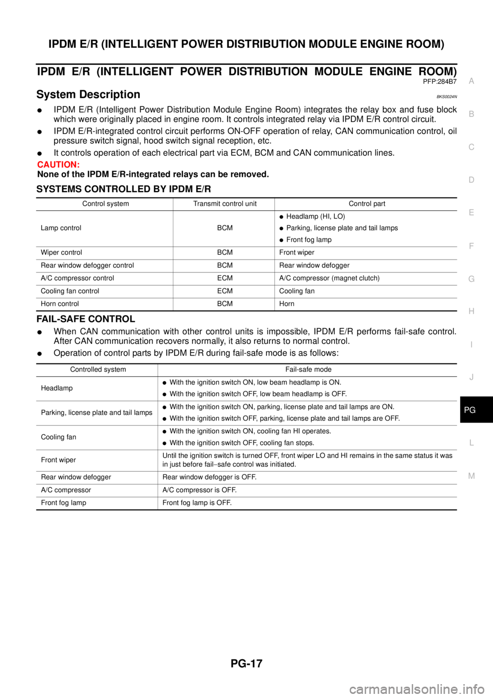
System DescriptionBKS0024N
�IPDM E/R (Intelligent Power Distribution Module Engine Room) integrates the relay box and fuse block
which were originally placed in engine room. It controls integrated relay via IPDM E/R control circuit.
�IPDM E/R-integrated control circuit performs ON-OFF operation of relay, CAN communication control, oil
pressure switch signal, hood switch signal reception, etc.
�It controls operation of each electrical part via ECM, BCM and CAN communication lines.
CAUTION:
None of the IPDM E/R-integrated relays can be removed.
SYSTEMS CONTROLLED BY IPDM E/R
FAIL-SAFE CONTROL
�When CAN communication with other control units is impossible, IPDM E/R performs fail-safe control.
After CAN communication recovers normally, it also returns to normal control.
�Operation of control parts by IPDM E/R during fail-safe mode is as follows:
Control system Transmit control unit Control part
Lamp control BCM
�Headlamp (HI, LO)
�Parking, license plate and tail lamps
�Front fog lamp
Wiper control BCM Front wiper
Rear window defogger control BCM Rear window defogger
A/C compressor control ECM A/C compressor (magnet clutch)
Cooling fan control ECM Cooling fan
Horn control BCM Horn
Controlled system Fail-safe mode
Headlamp
�With the ignition switch ON, low beam headlamp is ON.
�With the ignition switch OFF, low beam headlamp is OFF.
Parking, license plate and tail lamps
�With the ignition switch ON, parking, license plate and tail lamps are ON.
�With the ignition switch OFF, parking, license plate and tail lamps are OFF.
Cooling fan
�With the ignition switch ON, cooling fan HI operates.
�With the ignition switch OFF, cooling fan stops.
Front wiperUntil the ignition switch is turned OFF, front wiper LO and HI remains in the same status it was
in just before fail−safe control was initiated.
Rear window defogger Rear window defogger is OFF.
A/C compressor A/C compressor is OFF.
Front fog lamp Front fog lamp is OFF.
Page 3113 of 3502
FUSE BLOCK - JUNCTION BOX (J/B)
PG-79
C
D
E
F
G
H
I
J
L
MA
B
PG
FUSE BLOCK - JUNCTION BOX (J/B)PFP:24350
Terminal ArrangementBKS00256
CKIM0677E
Page 3114 of 3502
PG-80
FUSE, FUSIBLE LINK AND RELAY BOX
FUSE, FUSIBLE LINK AND RELAY BOXPFP:24382
Terminal ArrangementBKS00257
CKIM0678E
Page 3175 of 3502

SUNROOF
RF-11
C
D
E
F
G
H
J
K
L
MA
B
RF
System DescriptionBIS0010S
Power supplied at all time
�through 50A fusible link (letter M , located in the fuse and fusible link box)
�to BCM terminal 55
�through 15A fuse [No.17, located in the fuse block (J/B)]
�to BCM terminal 42
�through BCM terminal 54
�to sunroof motor assembly terminal 6.
With ignition switch ON or START position,
Power is supplied
�through 10A fuse [No.1, located in the fuse block (J/B)]
�to BCM terminal 38
�through BCM terminal 53
�to sunroof motor assembly terminal 3.
Ground is supplied
�to BCM terminal 52
�to sunroof motor assembly terminal 2
�through body grounds M71, M72.
TILT UP / SLIDE CLOSE OPERATION
When tilt up / slide close switch is pressed,
Ground is supplied
�to sunroof motor assembly terminal 5
�through sunroof switch terminal 3
�through sunroof switch terminal 2
�through body grounds M71, M72.
Then, the sunroof tilt up / slide close.
TILT DOWN / SLIDE OPEN OPERATION
When tilt down / slide open switch is pressed,
Ground is supplied
�to sunroof motor assembly terminal 1
�through sunroof switch terminal 1
�through sunroof switch terminal 2
�through body grounds M71, M72.
Then, the sunroof tilt down / slide open.
AUTO OPERATION
The power sunroof AUTO feature makes it possible to slide open and slide close or tilt up and tilt down the
sunroof without holding the sunroof switch in the slide open or slide close / tilt up or tilt down position.
TIMER FUNCTION
When the ignition switch is turned to OFF position from ON or START position, timer operates for 15 minutes.
Sunroof can be operated for 15 minutes.
Timer operation is canceled when one of the following conditions is satisfied.
�ignition switch : OFF→ ON
�front door switch (driver side) : ON (Open)→OFF (Closed)
ANTI-PINCH FUNCTION
The CPU of sunroof motor monitors the sunroof motor operation and the sunroof position (fully-closed or
other) by the signals from sunroof motor.
When sunroof motor detects an interruption during the following slide close and tilt down operation, sunroof
motor controls the sunroof motor for open and the sunroof will operate until full up position (during tilt down
operation) or 125 mm (4.92 in) or more in an open direction (during slide close operation)
Page 3179 of 3502

SUNROOF
RF-15
C
D
E
F
G
H
J
K
L
MA
B
RF
Work FlowBIS0010W
1. Check the symptom and customer's requests.
2. Understand the outline of system. Refer to RF-11, "
System Description" .
3. According to the trouble diagnosis chart, repair or replace the cause of the malfunction. Refer to RF-15,
"Trouble Diagnosis Chart by Symptom" .
4. Does sunroof system operate normally? If Yes, GO TO 5. If No, GO TO 3.
5. INSPECTION END.
Trouble Diagnosis Chart by SymptomBIS0010X
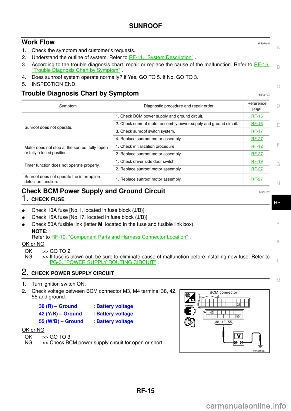
Check BCM Power Supply and Ground CircuitBIS0010Y
1. CHECK FUSE
�Check 10A fuse [No.1, located in fuse block (J/B)]
�Check 15A fuse [No.17, located in fuse block (J/B)]
�Check 50A fusible link (letter M located in the fuse and fusible link box).
NOTE:
Refer to RF-10, "
Component Parts and Harness Connector Location" .
OK or NG
OK >> GO TO 2.
NG >> If fuse is blown out, be sure to eliminate cause of malfunction before installing new fuse. Refer to
PG-3, "
POWER SUPPLY ROUTING CIRCUIT" .
2. CHECK POWER SUPPLY CIRCUIT
1. Turn ignition switch ON.
2. Check voltage between BCM connector M3, M4 terminal 38, 42,
55 and ground.
OK or NG
OK >> GO TO 3.
NG >> Check BCM power supply circuit for open or short.
Symptom Diagnostic procedure and repair orderReference
page
Sunroof does not operate.1. Check BCM power supply and ground circuit.RF-15
2. Check sunroof motor assembly power supply and ground circuit.RF-16
3. Check sunroof switch system.RF-17
4. Replace sunroof motor assembly.RF-27
Motor does not stop at the sunroof fully -open
or fully- closed position.1. Check initialization procedure.RF-12
2. Replace sunroof motor assembly.RF-27
Timer function does not operate properly.1. Check driver side door switch.RF-192. Replace sunroof motor assembly.RF-27
Sunroof does not operate the interruption
detection function.1. Replace sunroof motor assembly.RF-27
38 (R) – Ground : Battery voltage
42 (Y/R) – Ground : Battery voltage
55 (W/B) – Ground : Battery voltage
PIIA6160E
Page 3287 of 3502

AUTOMATIC DRIVE POSITIONER
SE-31
C
D
E
F
G
H
J
K
L
MA
B
SE
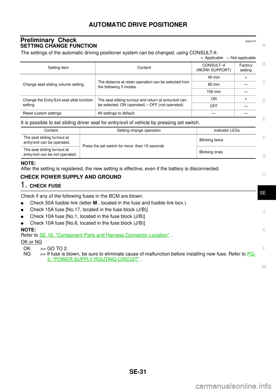
Preliminary CheckBIS0012P
SETTING CHANGE FUNCTION
The settings of the automatic driving positioner system can be changed, using CONSULT-II.
×: Applicable –: Not applicable
It is possible to set sliding driver seat for entry/exit of vehicle by pressing set switch.
NOTE:
After the setting is registered, the new setting is effective, even if the battery is disconnected.
CHECK POWER SUPPLY AND GROUND
1. CHECK FUSE
Check if any of the following fuses in the BCM are blown.
�Check 50A fusible link (letter M , located in the fuse and fusible link box.)
�Check 15A fuse [No.17, located in the fuse block (J/B)]
�Check 10A fuse [No.1, located in the fuse block (J/B)]
�Check 10A fuse [No.6, located in the fuse block (J/B)]
NOTE:
Refer to SE-16, "
Component Parts and Harness Connector Location" .
OK or NG
OK >> GO TO 2.
NG >> If fuse is blown, be sure to eliminate cause of malfunction before installing new fuse. Refer to PG-
3, "POWER SUPPLY ROUTING CIRCUIT" .
Setting item ContentCONSULT–II
(WORK SUPPORT)Factory
setting
Change seat sliding volume settingThe distance at retain operation can be selected from
the following 3 modes.40 mm×
80 mm —
150 mm —
Change the Entry/Exit seat slide function
settingThe seat sliding turnout and return at entry/exit can
be selected: ON (operated) – OFF (not operated)ON×
OFF —
Reset custom settings All settings to default. — —
Content Setting change operation Indicator LEDs
The seat sliding turnout at
entry/exit can be operated.
Press the set switch for more than 10 secondsBlinking twice
The seat sliding turnout at
entry/exit can be not operated.Blinking ones
Page:
< prev 1-8 9-16 17-24