Page 2291 of 3502
![NISSAN TEANA 2003 Service Manual TIMING CHAIN
EM-183
[VQ]
C
D
E
F
G
H
I
J
K
L
MA
EM
e. Tighten mounting bolts in numerical order as shown in the fig-
ure.
�There are two types of mounting bolt. Refer to the following
for locating b](/manual-img/5/57392/w960_57392-2290.png "NISSAN TEANA 2003 Service Manual TIMING CHAIN
EM-183
[VQ]
C
D
E
F
G
H
I
J
K
L
MA
EM
e. Tighten mounting bolts in numerical order as shown in the fig-
ure.
�There are two types of mounting bolt. Refer to the following
for locating b")
TIMING CHAIN
EM-183
[VQ]
C
D
E
F
G
H
I
J
K
L
MA
EM
e. Tighten mounting bolts in numerical order as shown in the fig-
ure.
�There are two types of mounting bolt. Refer to the following
for locating bolts.
f. After all bolts tightening, retighten them to the specified in
numerical order as shown in the figure.
�If liquid gasket protrudes, wipe it off immediately.
g. After installing rear timing chain case, check surface height dif-
ference between the following parts on the oil pan (upper)
mounting surface.
�If not within standard, repeat the installation procedure.
3. Install water pump with new O-rings. Refer to CO-46, "
WATER PUMP" .
4. Make sure that dowel pin hole, dowel pin and crankshaft key are
located as shown in the figure. (No. 1 cylinder at compression
TDC)
NOTE:
Though camshaft does not stop at the position as shown in the
figure, for the placement of cam nose, it is generally accepted
camshaft is placed for the same direction of the figure.
CAUTION:
Hole on small dia. side must be used for intake side dowel pin hole. Do not misidentify (ignore big
dia. side).
5. Install timing chain (secondary) and camshaft sprockets (INT and EXH) as follows:
CAUTION:
Mating marks between timing chain and sprockets slip easily. Confirm all mating mark positions
repeatedly during the installation process.Bolt length: Bolt position
20 mm (0.79 in) : 1, 2, 3, 6, 7, 8, 9, 10
16 mm (0.63 in) : Except the above
: 12.7 N·m (1.3 kg-m, 9 ft-lb)
SEM735G
Standard
Rear timing chain case to cylinder block:
−0.24 to 0.14 mm (−0.009 to 0.006 in)
SEM943G
Camshaft dowel pin hole (intake side)
: At cylinder head upper face side in each bank
Camshaft dowel pin (exhaust side)
: At cylinder head upper face side in each bank
Crankshaft key
: At cylinder head side of right bank
KBIA1073E
Page 2292 of 3502
![NISSAN TEANA 2003 Service Manual EM-184
[VQ]
TIMING CHAIN
a. Push plunger of chain tensioner (secondary) and keep it
pressed in with stopper pin.
b. Install timing chain (secondary) and camshaft sprockets (INT
and EXH).
�Align the](/manual-img/5/57392/w960_57392-2291.png "NISSAN TEANA 2003 Service Manual EM-184
[VQ]
TIMING CHAIN
a. Push plunger of chain tensioner (secondary) and keep it
pressed in with stopper pin.
b. Install timing chain (secondary) and camshaft sprockets (INT
and EXH).
�Align the")
EM-184
[VQ]
TIMING CHAIN
a. Push plunger of chain tensioner (secondary) and keep it
pressed in with stopper pin.
b. Install timing chain (secondary) and camshaft sprockets (INT
and EXH).
�Align the mating marks on timing chain (secondary) (gold link)
with the ones on camshaft sprockets (INT and EXH)
(punched), and install them.
NOTE:
�Mating marks for camshaft sprocket (INT) are on the back
side of camshaft sprocket (secondary).
�There are two types of mating mark, circle and oval types.
They should be used for the right and left banks, respec-
tively.
�Align dowel pin and pin hole on camshafts with the groove
and dowel pin on sprockets, and install them.
�On the intake side, align pin hole on the small diameter side of
the camshaft front end with dowel pin on the back side of
camshaft sprocket, and install them.
�On the exhaust side, align dowel pin on camshaft front end
with pin groove on camshaft sprocket, and install them.
�In case that positions of each mating mark and each dowel
pin are not fit on mating parts, make fine adjustment to the position holding the hexagonal portion on
camshaft with wrench or equivalent.
�Mounting bolts for camshaft sprockets must be tightened in the next step. Tightening them by hand is
enough to prevent the dislocation of dowel pins.
�It may be difficult to visually check the dislocation of mating
marks during and after installation. To make the matching
easier, make a mating mark on the top of sprocket teeth and
its extended line in advance with paint.
SEM430G
Right bank : Use circle type.
Left bank : Use oval type.
PBIC2981E
PBIC0891E
Page 2293 of 3502
TIMING CHAIN
EM-185
[VQ]
C
D
E
F
G
H
I
J
K
L
MA
EM
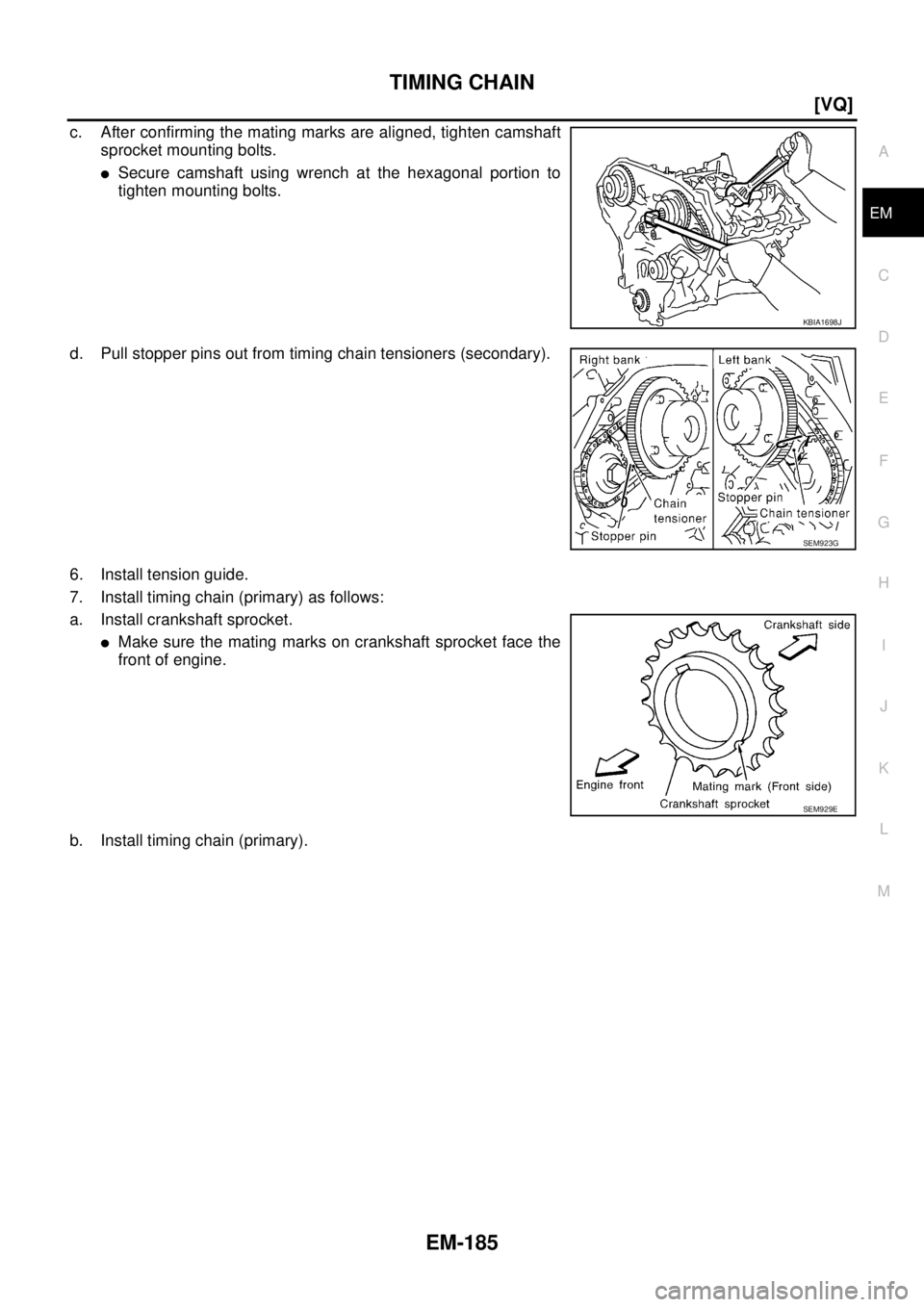
c. After confirming the mating marks are aligned, tighten camshaft
sprocket mounting bolts.
�Secure camshaft using wrench at the hexagonal portion to
tighten mounting bolts.
d. Pull stopper pins out from timing chain tensioners (secondary).
6. Install tension guide.
7. Install timing chain (primary) as follows:
a. Install crankshaft sprocket.
�Make sure the mating marks on crankshaft sprocket face the
front of engine.
b. Install timing chain (primary).
KBIA1698J
SEM923G
SEM929E
Page 2294 of 3502
EM-186
[VQ]
TIMING CHAIN
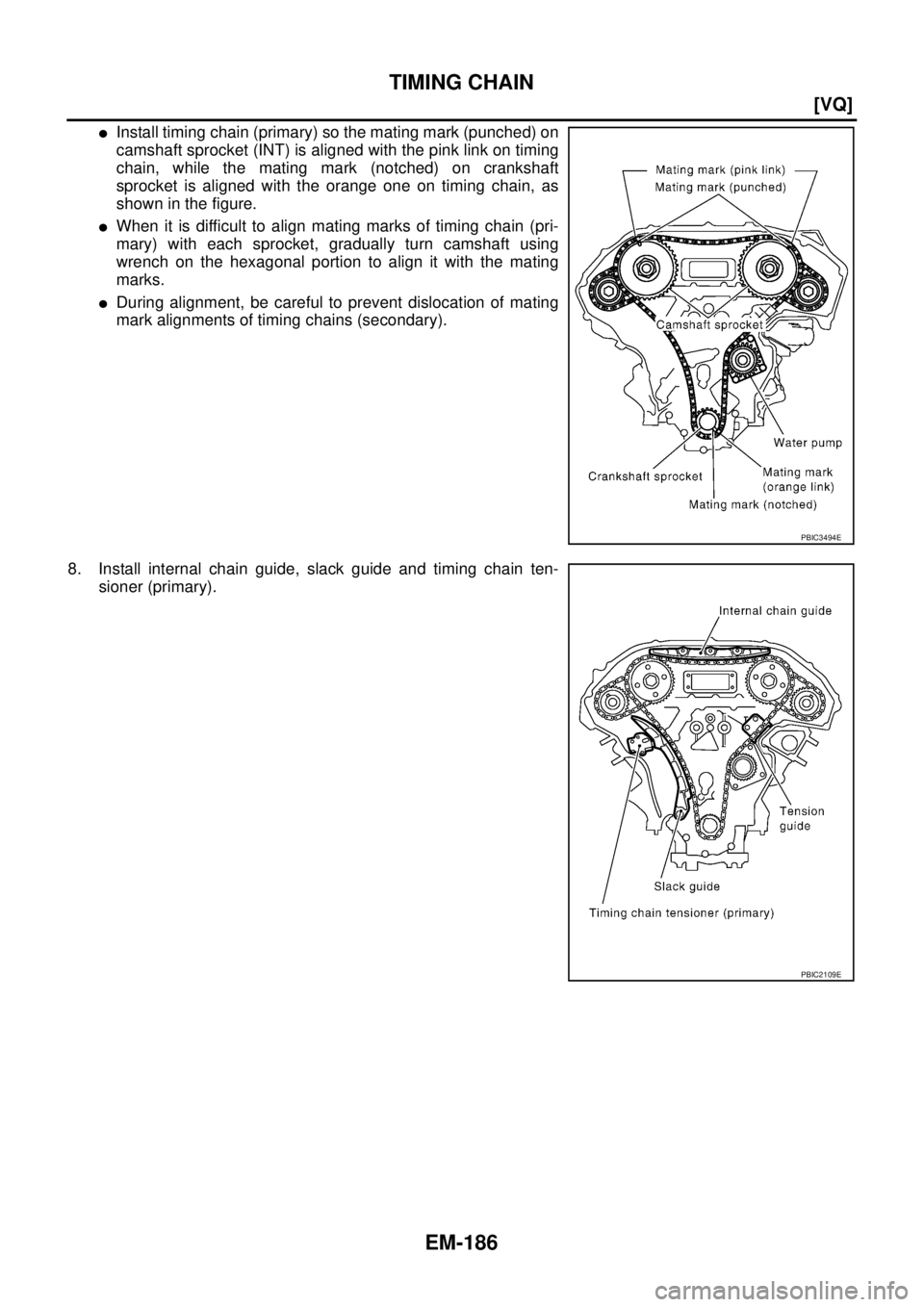
�Install timing chain (primary) so the mating mark (punched) on
camshaft sprocket (INT) is aligned with the pink link on timing
chain, while the mating mark (notched) on crankshaft
sprocket is aligned with the orange one on timing chain, as
shown in the figure.
�When it is difficult to align mating marks of timing chain (pri-
mary) with each sprocket, gradually turn camshaft using
wrench on the hexagonal portion to align it with the mating
marks.
�During alignment, be careful to prevent dislocation of mating
mark alignments of timing chains (secondary).
8. Install internal chain guide, slack guide and timing chain ten-
sioner (primary).
PBIC3494E
PBIC2109E
Page 2295 of 3502
![NISSAN TEANA 2003 Service Manual TIMING CHAIN
EM-187
[VQ]
C
D
E
F
G
H
I
J
K
L
MA
EM
CAUTION:
Do not overtighten slack guide mounting bolt. It is normal
for a gap to exist under the bolt seat when mounting bolt is
tightened to speci](/manual-img/5/57392/w960_57392-2294.png "NISSAN TEANA 2003 Service Manual TIMING CHAIN
EM-187
[VQ]
C
D
E
F
G
H
I
J
K
L
MA
EM
CAUTION:
Do not overtighten slack guide mounting bolt. It is normal
for a gap to exist under the bolt seat when mounting bolt is
tightened to speci")
TIMING CHAIN
EM-187
[VQ]
C
D
E
F
G
H
I
J
K
L
MA
EM
CAUTION:
Do not overtighten slack guide mounting bolt. It is normal
for a gap to exist under the bolt seat when mounting bolt is
tightened to specification.
9. Install the timing chain tensioner (primary) with the following procedure:
a. Pull plunger stopper tab up (or turn lever downward) so as to
remove plunger stopper tab from the ratchet of plunger.
NOTE:
Plunger stopper tab and lever are synchronized.
b. Push plunger into the inside of tensioner body.
c. Hold plunger in the fully compressed position by engaging
plunger stopper tab with the tip of ratchet.
d. To secure lever, insert stopper pin through hole of lever into ten-
sioner body hole.
�The lever parts and the tab are synchronized. Therefore, the
plunger will be secured under this condition.
NOTE:
Figure shows the example of 1.2 mm (0.047 in) diameter thin screwdriver being used as the stopper pin.
e. Install timing chain tensioner (primary).
�Remove any dirt and foreign materials completely from the
back and the mounting surfaces of timing chain tensioner (pri-
mary).
f. Pull out stopper pin after installing, and then release plunger.
10. Make sure again that the mating marks on each sprocket and each timing chain have not slipped out of
alignment.
11. Install new O-rings on rear timing chain case.
12. Install new front oil seal on front timing chain case.
�Apply new engine oil to both oil seal lip and dust seal lip.
PBIC2633E
PBIC3568E
PBIC3569E
PBIC2548E
Page 2298 of 3502
![NISSAN TEANA 2003 Service Manual EM-190
[VQ]
TIMING CHAIN
b. Apply a continuous bead of liquid gasket with tube presser [SST:
WS39930000] to intake valve timing control covers as shown in
the figure.
Use Genuine Liquid Gasket or eq](/manual-img/5/57392/w960_57392-2297.png "NISSAN TEANA 2003 Service Manual EM-190
[VQ]
TIMING CHAIN
b. Apply a continuous bead of liquid gasket with tube presser [SST:
WS39930000] to intake valve timing control covers as shown in
the figure.
Use Genuine Liquid Gasket or eq")
EM-190
[VQ]
TIMING CHAIN
b. Apply a continuous bead of liquid gasket with tube presser [SST:
WS39930000] to intake valve timing control covers as shown in
the figure.
Use Genuine Liquid Gasket or equivalent.
c. Install new collared O-ring in front timing chain case oil hole (left
and right sides).
d. Being careful not to move seal rings from the installation grooves, align dowel pins on front timing chain
case with the holes to install intake valve timing control covers.
e. Tighten mounting bolts in numerical order as shown in the fig-
ure.
16. Install crankshaft pulley as follows:
a. Install crankshaft pulley, taking care not to damage front oil seal.
�When press-fitting crankshaft pulley with plastic hammer, tap on its center portion (not circumference).
b. Fix crankshaft with pulley holder [SST: KV10109300].
c. Tighten crankshaft pulley bolt.
d. Place a matching mark (A) on crank pulley (1) aligning with the
matching (B) of crank pulley mounting bolt (2). Tighten the bolts
90 degrees (one marks).
SBIA0492E
PBIC2631E
PBIC0918E
: 44.1 N·m (4.5 kg-m, 33 ft-lb)
PBIC4627J
Page 2301 of 3502
![NISSAN TEANA 2003 Service Manual CAMSHAFT
EM-193
[VQ]
C
D
E
F
G
H
I
J
K
L
MA
EM
2. Install engine sub-attachment with engine stand shaft [SST: KV10117001 and KV10106500] to right side
of cylinder block, then lift engine, and mount](/manual-img/5/57392/w960_57392-2300.png "NISSAN TEANA 2003 Service Manual CAMSHAFT
EM-193
[VQ]
C
D
E
F
G
H
I
J
K
L
MA
EM
2. Install engine sub-attachment with engine stand shaft [SST: KV10117001 and KV10106500] to right side
of cylinder block, then lift engine, and mount")
CAMSHAFT
EM-193
[VQ]
C
D
E
F
G
H
I
J
K
L
MA
EM
2. Install engine sub-attachment with engine stand shaft [SST: KV10117001 and KV10106500] to right side
of cylinder block, then lift engine, and mount it onto engine stand [SST: ST0501S000]. Refer to EM-228,
"CYLINDER BLOCK" .
3. Remove front timing chain case, camshaft sprocket, timing chain and rear timing chain case. Refer to EM-
173, "TIMING CHAIN" .
4. Remove camshaft position sensors (PHASE) (right and left
banks) from cylinder head back side.
CAUTION:
�Handle carefully to avoid dropping and shocks.
�Do not disassemble.
�Do not allow metal powder to adhere to magnetic part at
sensor tip.
�Do not place sensors in a location where they are
exposed to magnetism.
5. Remove intake valve timing control solenoid valves.
�Discard intake valve timing control solenoid valve gaskets and
use new gaskets for installation.
6. Remove camshaft brackets.
�Mark camshafts, camshaft brackets and bolts so they are placed in the same position and direction for
installation.
�Equally loosen camshaft bracket bolts in several steps in the
reverse order as shown in the figure.
7. Remove camshafts.
8. Remove valve lifters.
KBIA1046E
SEM443GA
PBIC2050E
Page:
< prev 1-8 9-16 17-24