Page 3133 of 3502

POWER STEERING GEAR AND LINKAGE
PS-19
C
D
E
F
H
I
J
K
L
MA
B
PS
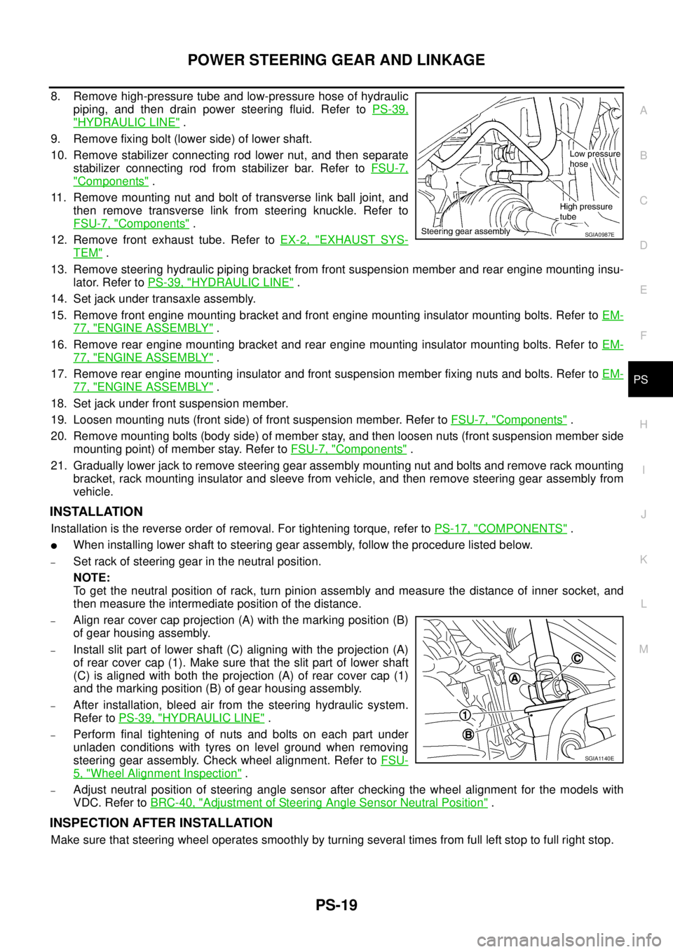
8. Remove high-pressure tube and low-pressure hose of hydraulic
piping, and then drain power steering fluid. Refer to PS-39,
"HYDRAULIC LINE" .
9. Remove fixing bolt (lower side) of lower shaft.
10. Remove stabilizer connecting rod lower nut, and then separate
stabilizer connecting rod from stabilizer bar. Refer to FSU-7,
"Components" .
11. Remove mounting nut and bolt of transverse link ball joint, and
then remove transverse link from steering knuckle. Refer to
FSU-7, "
Components" .
12. Remove front exhaust tube. Refer to EX-2, "
EXHAUST SYS-
TEM" .
13. Remove steering hydraulic piping bracket from front suspension member and rear engine mounting insu-
lator. Refer to PS-39, "
HYDRAULIC LINE" .
14. Set jack under transaxle assembly.
15. Remove front engine mounting bracket and front engine mounting insulator mounting bolts. Refer to EM-
77, "ENGINE ASSEMBLY" .
16. Remove rear engine mounting bracket and rear engine mounting insulator mounting bolts. Refer to EM-
77, "ENGINE ASSEMBLY" .
17. Remove rear engine mounting insulator and front suspension member fixing nuts and bolts. Refer to EM-
77, "ENGINE ASSEMBLY" .
18. Set jack under front suspension member.
19. Loosen mounting nuts (front side) of front suspension member. Refer to FSU-7, "
Components" .
20. Remove mounting bolts (body side) of member stay, and then loosen nuts (front suspension member side
mounting point) of member stay. Refer to FSU-7, "
Components" .
21. Gradually lower jack to remove steering gear assembly mounting nut and bolts and remove rack mounting
bracket, rack mounting insulator and sleeve from vehicle, and then remove steering gear assembly from
vehicle.
INSTALLATION
Installation is the reverse order of removal. For tightening torque, refer to PS-17, "COMPONENTS" .
�When installing lower shaft to steering gear assembly, follow the procedure listed below.
–Set rack of steering gear in the neutral position.
NOTE:
To get the neutral position of rack, turn pinion assembly and measure the distance of inner socket, and
then measure the intermediate position of the distance.
–Align rear cover cap projection (A) with the marking position (B)
of gear housing assembly.
–Install slit part of lower shaft (C) aligning with the projection (A)
of rear cover cap (1). Make sure that the slit part of lower shaft
(C) is aligned with both the projection (A) of rear cover cap (1)
and the marking position (B) of gear housing assembly.
–After installation, bleed air from the steering hydraulic system.
Refer to PS-39, "
HYDRAULIC LINE" .
–Perform final tightening of nuts and bolts on each part under
unladen conditions with tyres on level ground when removing
steering gear assembly. Check wheel alignment. Refer to FSU-
5, "Wheel Alignment Inspection" .
–Adjust neutral position of steering angle sensor after checking the wheel alignment for the models with
VDC. Refer to BRC-40, "
Adjustment of Steering Angle Sensor Neutral Position" .
INSPECTION AFTER INSTALLATION
Make sure that steering wheel operates smoothly by turning several times from full left stop to full right stop.
SGIA0987E
SGIA1140E
Page 3160 of 3502
RAX-2
NOISE, VIBRATION AND HARSHNESS (NVH) TROUBLESHOOTING
NOISE, VIBRATION AND HARSHNESS (NVH) TROUBLESHOOTINGPFP:00003
NVH Troubleshooting ChartBDS0007X
Use chart below to help you find the cause of the symptom. If necessary, repair or replace these parts.
×: ApplicableReference page
FSU-7—
NVH in RAX and RSU sections
NVH in WT section
NVH in WT section
NVH in BR section
Possible cause and Suspected parts
Improper installation, looseness
Parts interference
Rear AXLE AND Rear SUSPENSION
TIRES
ROAD WHEELS
BRAKES
Symptom Rear axleNoise××××××
Shake××××××
Vibration×××× ×
Shimmy××××××
Judder× ××××
Poor quality ride or handling××××××
Page 3196 of 3502
RSU-4
NOISE, VIBRATION AND HARSHNESS (NVH) TROUBLESHOOTING
NOISE, VIBRATION AND HARSHNESS (NVH) TROUBLESHOOTINGPFP:00003
NVH Troubleshooting ChartBES0003Z
Use chart below to help you find the cause of the symptom. If necessary, repair or replace these parts.
×: ApplicableReference page
RSU-7RSU-10
—
—
—
RSU-7RSU-5RSU-16
NVH in RAX and RSU sections
NVH in WT section
NVH in WT section
NVH in BR section
NVH in PS section
Possible cause and Suspected parts
Improper installation, looseness
Shock absorber deformation, damage or deflection
Bushing or mounting deterioration
Parts interference
Spring fatigue
Suspension looseness
Incorrect wheel alignment
Stabilizer bar fatigue
REAR AXLE AND REAR SUSPENSION
TIRES
ROAD WHEELS
BRAKES
STEERING
Symptom Rear suspensionNoise×××××× ×××××
Shake×××× × ×××××
Vibration××××× ×× ×
Shimmy×××× × ×××××
Judder ××× ×××××
Poor quality ride or
handling××××× ×××××
Page 3197 of 3502

REAR SUSPENSION ASSEMBLY
RSU-5
C
D
F
G
H
I
J
K
L
MA
B
RSU
REAR SUSPENSION ASSEMBLYPFP:55020
On-Vehicle Inspection BES00040
Make sure that the mounting conditions (looseness, back lash) of each components and component status
(wear, damage) are normal.
INSPECTION OF SUSPENSION ARM BALL JOINT END PLAY
Measure axial end play by placing an iron pry bar or a similar item between suspension arm and axle housing
prying up and down.
CAUTION:
Be careful not to damage ball joint boot. Do not damage installation position by applying excessive
force.
SHOCK ABSORBER INSPECTION
Check for oil leakage, damage, and breakage of installation positions.
Wheel Alignment InspectionBES00041
DESCRIPTION
Measure the wheel alignment under unladen conditions.
NOTE:
“Unladen conditions” mean that fuel, engine coolant, and lubricant are full. A spare tire, a jack, hand tools and
mats are in designated positions.
PRELIMINARY CHECK
1. Check tires for improper air pressure and wear.
2. Check road wheels for runout. Refer to WT-3, "
ROAD WHEEL" .
3. Check wheel bearing axial end play. Refer to RAX-3, "
WHEEL BEARING INSPECTION" .
4. Check suspension arm ball joint axial end play. Refer to RSU-11, "
Ball Joint Inspection" .
5. Check shock absorber operation.
6. Check each mounting point of axle housing and suspension for looseness and deformation.
7. Check each link, arm, and member for cracks, deformation, and other damage.
8. Check vehicle height (posture).
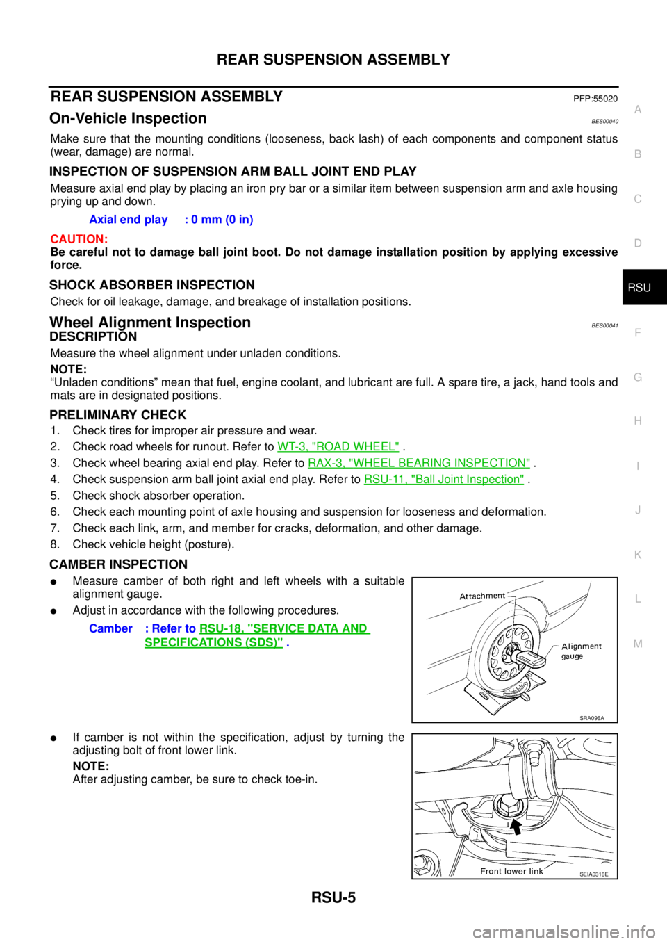
CAMBER INSPECTION
�Measure camber of both right and left wheels with a suitable
alignment gauge.
�Adjust in accordance with the following procedures.
�If camber is not within the specification, adjust by turning the
adjusting bolt of front lower link.
NOTE:
After adjusting camber, be sure to check toe-in.Axial end play : 0 mm (0 in)
Camber : Refer to RSU-18, "
SERVICE DATA AND
SPECIFICATIONS (SDS)" .
SRA096A
SEIA0318E
Page 3434 of 3502

WT-2
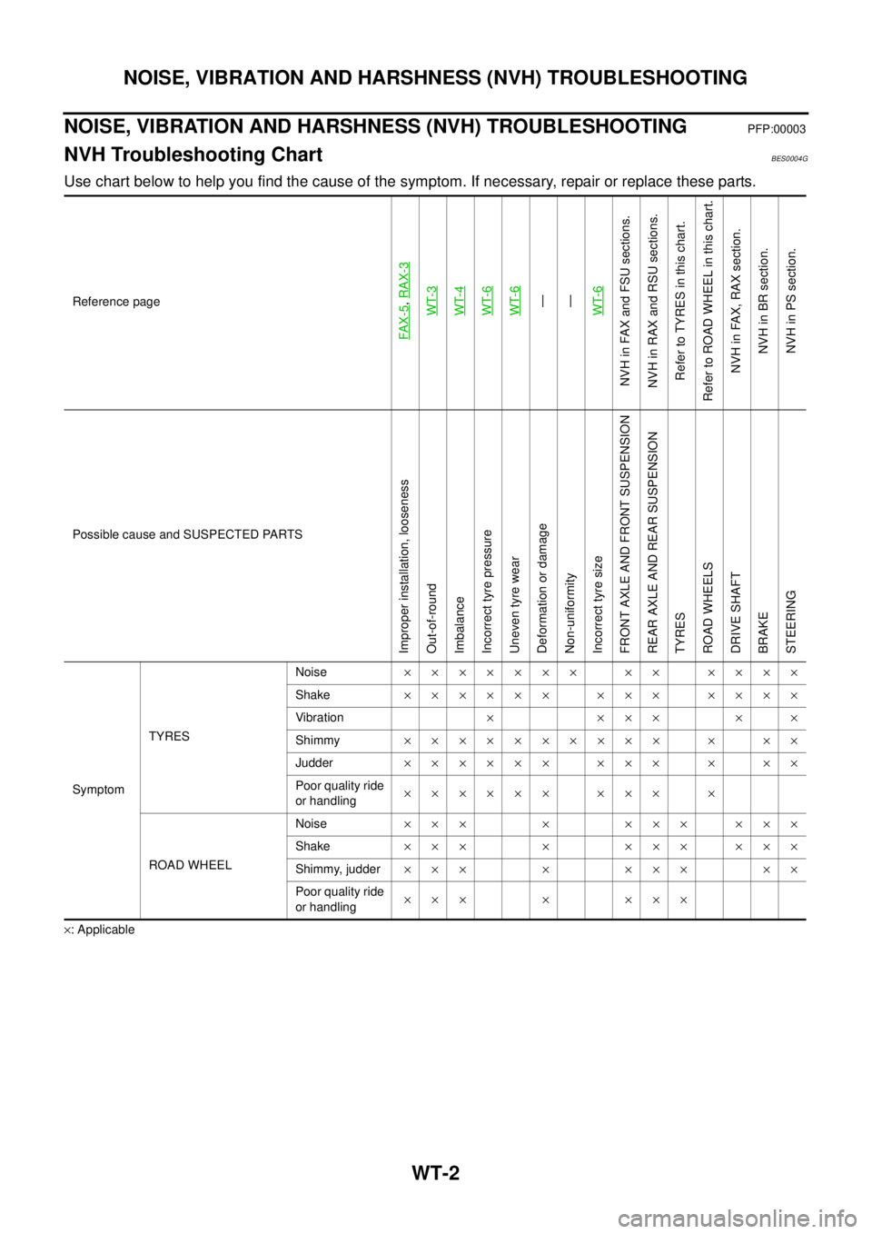
NOISE, VIBRATION AND HARSHNESS (NVH) TROUBLESHOOTING
NOISE, VIBRATION AND HARSHNESS (NVH) TROUBLESHOOTINGPFP:00003
NVH Troubleshooting ChartBES0004G
Use chart below to help you find the cause of the symptom. If necessary, repair or replace these parts.
×: ApplicableReference page
FAX-5
, RAX-3WT-3
WT-4
WT-6WT-6—
—
WT-6
NVH in FAX and FSU sections.
NVH in RAX and RSU sections.
Refer to TYRES in this chart.
Refer to ROAD WHEEL in this chart.
NVH in FAX, RAX section.
NVH in BR section.
NVH in PS section.
Possible cause and SUSPECTED PARTS
Improper installation, looseness
Out-of-round
Imbalance
Incorrect tyre pressure
Uneven tyre wear
Deformation or damage
Non-uniformity
Incorrect tyre size
FRONT AXLE AND FRONT SUSPENSION
REAR AXLE AND REAR SUSPENSION
TYRES
ROAD WHEELS
DRIVE SHAFT
BRAKE
STEERING
SymptomTYRESNoise××××××× ×× ××××
Shake×××××× ××× ××××
Vibration× ××× × ×
Shimmy×××××××××× × ××
Judder×××××× ××× × ××
Poor quality ride
or handling×××××× ××× ×
ROAD WHEELNoise××× × ××× ×××
Shake××× × ××× ×××
Shimmy, judder××× × ××× ××
Poor quality ride
or handling××× × ×××
Page:
< prev 1-8 9-16 17-24