Page 224 of 3502
AT-216
A/T SHIFT LOCK SYSTEM
A/T SHIFT LOCK SYSTEMPFP:34950
DescriptionBCS0014Z
�The electrical key interlock mechanism also operates as a shift lock:
With the ignition switch turned to ON, selector lever cannot be shifted from “P” to any other position unless
brake pedal is depressed.
With the key removed, selector lever cannot be shifted from “P” to any other position.
The key cannot be removed unless selector lever is placed in “P”.
�The shift lock and key interlock mechanisms are controlled by the ON-OFF operation of the shift lock sole-
noid and by the operation of the rotator and slider located inside key cylinder, respectively.
Shift Lock System Electrical Parts LocationBCS00150
NOTE:
This emergency lever insures that when battery is off ignition key cannot be removed.Inthe situation like this,
by operating this lever, ignition key can be removed.
SCIA5729E
Page 225 of 3502
A/T SHIFT LOCK SYSTEM
AT-217
D
E
F
G
H
I
J
K
L
MA
B
AT
Wiring Diagram — AT — SHIFTBCS00151
WITHOUT INTELLIGENT KEY
TCWM0523E
Page 226 of 3502
AT-218
A/T SHIFT LOCK SYSTEM
TCWM0524E
Page 227 of 3502
A/T SHIFT LOCK SYSTEM
AT-219
D
E
F
G
H
I
J
K
L
MA
B
AT
WITH INTELLIGENT KEY
TCWM0525E
Page 228 of 3502
AT-220
A/T SHIFT LOCK SYSTEM
TCWM0526E
Page 229 of 3502

A/T SHIFT LOCK SYSTEM
AT-221
D
E
F
G
H
I
J
K
L
MA
B
AT
Shift Lock Control Unit Reference ValuesBCS00152
SHIFT LOCK HARNESS CONNECTOR TERMINALS LAYOUT
SHIFT LOCK CONTROL UNIT INSPECTION TABLE
Data are reference values.
NOTE:
Make sure that the pointer swings only momentarily because the output time is so short. If the inspection is done with an oscilloscope, it
should be observed that the power source voltage lasts for 3.5 to 10 ms.
SCIA2004E
Terminal Wire color Item Condition Judgement standard
1 Y/R Power source Always Battery voltage
2LDetention switch (for
key)When selector lever is not in “P” position with
key inserted.Battery voltage
When selector lever is in “P” position with key
inserted.Approx. 0 V
3RDetention switch (for
shift)When selector lever is not “P” position. Battery voltage
When selector lever is “P” position. Approx. 0 V
4 R/G Stop lamp switchWhen brake pedal is depressed Battery voltage
When brake pedal is released Approx. 0 V
5V/WVehicle speed signal
(8pulse signal)Speed meter is operatedRefer to DI-12, "
Terminals and Ref-
erence Value for Combination
Meter" .
6 G Ignition switch signalIgnition switch: OFF Approx. 0 V
Ignition switch: ON Battery voltage
7 R/W Shift lock solenoid
�When selector lever is in “P” position, brake
pedal is depressed, and ignition switch is ON.
�When selector lever is not in “P” position,
ignition switch is ON, and vehicle speed is
10km/h or less.
�For 3minutes after selector lever is not in “P”
position, vehicle speed is 10 km/h or less,
and ignition switch is ON → OFF.Approx. 0 V
Except the above Battery voltage
8 B Ground Always Approx. 0 V
9 G/B Key lock solenoidWhen selector lever is not “P” position.Battery voltage for approx. 0.1 sec.
(Note)
When selector lever is “P” position. Approx. 0 V
10 G/WKey unlock solenoidWhen selector lever is “P” position with ignition
switch is OFF.Battery voltage for approx. 0.1 sec.
(Note)
When selector lever is not “P” position with igni-
tion switch is OFF.Approx. 0 V
Page 230 of 3502

AT-222
A/T SHIFT LOCK SYSTEM
Component InspectionBCS00153
SHIFT LOCK SOLENOID
Check operation by applying battery voltage to A/T device harness
connector terminal.
CAUTION:
Be sure to apply the voltage of the correct polarity to the
respective terminals. Otherwise, the part may be damaged.
DETENTION SWITCH (FOR KEY)
Check continuity between terminals of A/T device harness connector
terminals.
DETENTION SWITCH (FOR SHIFT)
Check continuity between terminals of A/T device harness connector
terminals.
KEY LOCK SOLENOID
Key Lock (With Intelligent Key)
Check operation by applying battery voltage to ignition knob switch,
key switch and key lock solenoid harness connector terminal.
CAUTION:
Be careful not to cause burnout of harness.
Connector Terminal
M62 9 (Battery voltage) - 10 (Ground)
SCIA6641E
Condition Connector Terminal Continuity
When selector lever is “P”
position.
M62 5 - 6No
When selector lever is not “P”
position.Ye s
SCIA6642E
Condition Connector Terminal Continuity
When selector lever is “P”
position.
M62 13 - 14No
When selector lever is not “P”
position.Ye s
SCIA6643E
Connector Terminal
M20 6 (Battery voltage) - 5 (Ground)
SCIA6645E
Page 231 of 3502

A/T SHIFT LOCK SYSTEM
AT-223
D
E
F
G
H
I
J
K
L
MA
B
AT
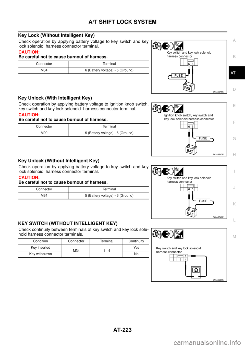
Key Lock (Without Intelligent Key)
Check operation by applying battery voltage to key switch and key
lock solenoid harness connector terminal.
CAUTION:
Be careful not to cause burnout of harness.
Key Unlock (With Intelligent Key)
Check operation by applying battery voltage to ignition knob switch,
key switch and key lock solenoid harness connector terminal.
CAUTION:
Be careful not to cause burnout of harness.
Key Unlock (Without Intelligent Key)
Check operation by applying battery voltage to key switch and key
lock solenoid harness connector terminal.
CAUTION:
Be careful not to cause burnout of harness.
KEY SWITCH (WITHOUT INTELLIGENT KEY)
Check continuity between terminals of key switch and key lock sole-
noid harness connector terminals.
Connector Terminal
M34 6 (Battery voltage) - 5 (Ground)
SCIA6646E
Connector Terminal
M20 5 (Battery voltage) - 6 (Ground)
SCIA6647E
Connector Terminal
M34 5 (Battery voltage) - 6 (Ground)
SCIA6648E
Condition Connector Terminal Continuity
Key inserted
M34 1 - 4Ye s
Key withdrawn No
SCIA6650E