Page 402 of 3502

ATC-24
AIR CONDITIONER CONTROL
AIR CONDITIONER CONTROLPFP:27500
Description of Air Conditioner LAN Control SystemBJS000FJ
The LAN (Local Area Network) system consists of unified meter and A/C amp., mode door motor, air mix door
motors and intake door motor.
A configuration of these components is shown in the figure below.
System ConstructionBJS000FK
A small network is constructed between the unified meter and A/C amp., air mix door motors, mode door
motor and intake door motor. The unified meter and A/C amp. and motors are connected by data transmission
lines and motor power supply lines. The LAN network is built through the ground circuits of each door motor.
Addresses, motor opening angle signals, motor stop signals and error checking messages are all transmitted
through the data transmission lines connecting the unified meter and A/C amp. and each door motor.
The following functions are contained in LCUs built into the air mix door motors, the mode door motor and the
intake door motor.
�Address
�Motor opening angle signals
�Data transmission
�Motor stop and drive decision
�Opening angle sensor (PBR function)
�Comparison
�Decision (Unified meter and A/C amp. indicated value and motor opening angle comparison)
OPERATION
The unified meter and A/C amp. receives data from each of the sensors. The unified meter and A/C amp.
sends mode door, air mix door and intake door opening angle data to the mode door motor LCU, air mix door
motor LCU and intake door motor LCU.
The mode door motor, air mix door motors and intake door motor read their respective signals according to the
address signal. Opening angle indication signals received from the unified meter and A/C amp. and each of
the motor position sensors is compared by the LCUs in each door motor with the existing decision and open-
ing angles. Subsequently, HOT/COLD, DEF/VENT and FRE/REC operation is selected. The new selection
data is returned to the unified meter and A/C amp.
SJIA1609E
RJIA1747E
Page 428 of 3502

ATC-50
TROUBLE DIAGNOSIS
12. CHECK CAN COMMUNICATION ERROR
1. Press intake switch.
2. CAN communication error between the unified meter and A/C
amp. and the display unit or display control unit can be detected
as self-diagnosis results. (If plural errors occur, the display of
each error will blink twice for 0-5 second intervals.) .
OK or NG
OK >> 1. Turn ignition switch OFF or AUTO switch ON.
2. INSPECTION END
NG >> Go to CAN communication. Refer to LAN-49, "
CAN Sys-
tem Specification Chart" .
�Unified meter and A/C amp. - Display unit or Display
control unit.
13. CHECK MALFUNCTIONING SENSOR
Refer to the following chart for malfunctioning code No.
(If two or more sensors malfunction, corresponding code Nos. blink respectively twice.)
*1: Perform self-diagnosis STEP-2 under sunshine.
When performing indoors, aim a light (more than 60 W) at sunload sensor, otherwise code No. 25 will indicate
despite that sunload sensor is functioning properly.
*2: AT C - 9 6 , "
DIAGNOSIS PROCEDURE FOR AMBIENT SENSOR" .
*3: ATC-100, "
DIAGNOSIS PROCEDURE FOR IN-VEHICLE SENSOR" .
*4: ATC-105, "
DIAGNOSIS PROCEDURE FOR INTAKE SENSOR" .
*5: ATC-102, "
DIAGNOSIS PROCEDURE FOR SUNLOAD SENSOR" .
*6: AT C - 6 8 , "
DIAGNOSIS PROCEDURE FOR AIR MIX DOOR MOTOR PBR" .
>> INSPECTION END
RJIA1762E
Code No. Malfunctioning sensor (Including circuits) Reference page
21 / −21 Ambient sensor *2
22 / −22 In-vehicle sensor *3
24 / −24 Intake sensor *4
25 / −25
Sunload sensor
*1*5
26 / −26 Air mix door motor PBR (Driver side)
*6
27 / −27 Air mix door motor PBR (Passenger side)
PJIA0022E
Page 429 of 3502

TROUBLE DIAGNOSIS
ATC-51
C
D
E
F
G
H
I
K
L
MA
B
AT C
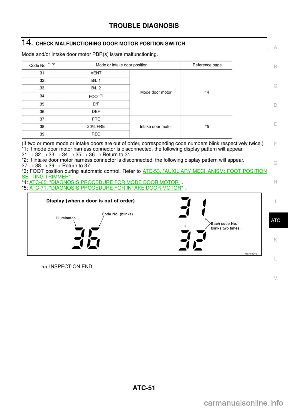
14. CHECK MALFUNCTIONING DOOR MOTOR POSITION SWITCH
Mode and/or intake door motor PBR(s) is/are malfunctioning.
(If two or more mode or intake doors are out of order, corresponding code numbers blink respectively twice.)
*1: If mode door motor harness connector is disconnected, the following display pattern will appear.
31 → 32 → 33 → 34 → 35 → 36 → Return to 31
*2: If intake door motor harness connector is disconnected, the following display pattern will appear.
37 → 38 → 39 → Return to 37
*3: FOOT position during automatic control. Refer to AT C - 5 3 , "
AUXILIARY MECHANISM: FOOT POSITION
SETTING TRIMMER" .
*4: AT C - 6 5 , "
DIAGNOSIS PROCEDURE FOR MODE DOOR MOTOR" .
*5: AT C - 7 1 , "
DIAGNOSIS PROCEDURE FOR INTAKE DOOR MOTOR" .
>> INSPECTION END
Code No. *1 *2Mode or intake door position Reference page
31 VENT
Mode door motor *4 32 B/L 1
33 B/L 2
34
FOOT
*3
35 D/F
36 DEF
37 FRE
Intake door motor *5 38 20% FRE
39 REC
RJIA0494E
Page 442 of 3502

ATC-64
TROUBLE DIAGNOSIS
SYSTEM DESCRIPTION
Component Parts
Mode door control system components are:
�Unified meter and A/C amp.
�Mode door motor (LCU)
�A/C LAN system (PBR built-in mode door motor, air mix door motor and intake door motor)
�In-vehicle sensor
�Ambient sensor
�Sunload sensor
�Intake sensor
System Operation
The unified meter and A/C amp. receives data from each of the sensors. The unified meter and A/C amp.
sends air mix door, mode door and intake door opening angle data to the air mix door motor LCU, mode door
motor LCU and intake door motor LCU.
The air mix door motor, mode door motor and intake door motor read their respective signals according to the
address signal. Opening angle indication signals received from the unified meter and A/C amp. and each of
the motor position sensors are compared by the LCUs in each door motor with the existing decision and open-
ing angles. Subsequently, HOT/COLD, DEF/VENT and FRE/REC operation is selected. The new selection
data is returned to the unified meter and A/C amp.
RJIA1777E
Page 445 of 3502

TROUBLE DIAGNOSIS
ATC-67
C
D
E
F
G
H
I
K
L
MA
B
AT C
SYSTEM DESCRIPTION
Component Parts
Air mix door control system components are:
�Unified meter and A/C amp.
�Air mix door motor (LCU)
�A/C LAN system (PBR built-in mode door motor, air mix door motor and intake door motor)
�In-vehicle sensor
�Ambient sensor
�Sunload sensor
�Intake sensor
System Operation
The unified meter and A/C amp. receives data from each of the sensors. The unified meter and A/C amp.
sends air mix door, mode door and intake door motor opening angle data to the air mix door motor LCUs,
mode door motor LCU and intake door motor LCU.
The air mix door motors, mode door motor and intake door motor read their respective signals according to the
address signal. Opening angle indication signals received from the unified meter and A/C amp. and each of
the motor position sensors are compared by the LCUs in each door motor with the existing decision and open-
ing angles. Subsequently, HOT/COLD, DEF/VENT and FRE/REC operation is selected. The new selection
data are returned to the unified meter and A/C amp.
Air Mix Door Control Specification
RJIA1781E
RJIA1782E
Page 504 of 3502
ATC-126
DUCTS AND GRILLES
DUCTS AND GRILLESPFP:27860
Removal and InstallationBJS000HM
REMOVAL
Removal of Center Ventilator Grilles
1. Remove cluster lid D. Refer to IP-10, "INSTRUMENT PANEL ASSEMBLY" .
2. Remove mounting clips, and then remove center ventilator
grilles.
1. Defroster nozzle 2. Duct assembly 3. Instrument panel
4. Side defroster grille (left) 5. Side ventilator grille (left) 6. Center ventilator grille (left)
7. Center ventilator grille (right) 8. Side ventilator grille (right) 9. Side defroster grille (right)
SJIA1653E
RJIA2209E
Page 509 of 3502
REFRIGERANT LINES
ATC-131
C
D
E
F
G
H
I
K
L
MA
B
AT C
REFRIGERANT LINESPFP:92600
HFC-134a (R-134a) Service ProcedureBJS000HN
SETTING OF SERVICE TOOLS AND EQUIPMENT
Discharging Refrigerant
WARNING:
Avoid breathing A/C refrigerant and lubricant vapor or mist. Exposure may irritate eyes, nose and
throat. Use only approved recovery/recycling equipment to discharge HFC-134a (R-134a) refrigerant. If
accidental system discharge occurs, ventilate work area before resuming service. Additional health
and safety information may be obtained from refrigerant and lubricant manufacturers.
Evacuating System and Charging Refrigerant
SHA539DE
SHA540DC
Page 589 of 3502

INTEGRATED COLOR DISPLAY SYSTEM
AV-61
C
D
E
F
G
H
I
J
L
MA
B
AV
INTEGRATED COLOR DISPLAY SYSTEMPFP:28090
System DescriptionBKS0027J
For system operation information, refer to Owner's Manual.
INTEGRATED COLOR DISPLAY SYSTEM
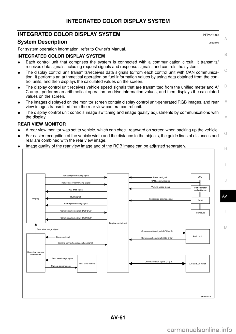
�Each control unit that comprises the system is connected with a communication circuit. It transmits/
receives data signals including request signals and response signals, and controls the system.
�The display control unit transmits/receives data signals to/from each control unit with CAN communica-
tion. It performs an arithmetical operation on fuel information values by using data obtained from the con-
trol units, and then displays the calculated values on the screen.
�The display control unit receives vehicle speed signals that are transmitted from the unified meter and A/
C amp., performs an arithmetical operation on drive information values, and then displays the calculated
values on the screen.
�The images displayed on the monitor screen contain display control unit-generated RGB images, and rear
view images transmitted from the rear view camera control unit.
�The display control unit controls image switching and image quality adjustments by communications with
the display.
REAR VIEW MONITOR
�A rear view monitor was set to vehicle, which can check rearward on screen when backing up the vehicle.
�For easier recognition of the vehicle width and the distance to the objects, the guide lines of distances and
rear are combined with the rear view image.
�Image quality of the rear view image and of the RGB image can be adjusted separately.
SKIB8807E