2003 NISSAN TEANA accelerator
[x] Cancel search: acceleratorPage 2576 of 3502

IDX-2
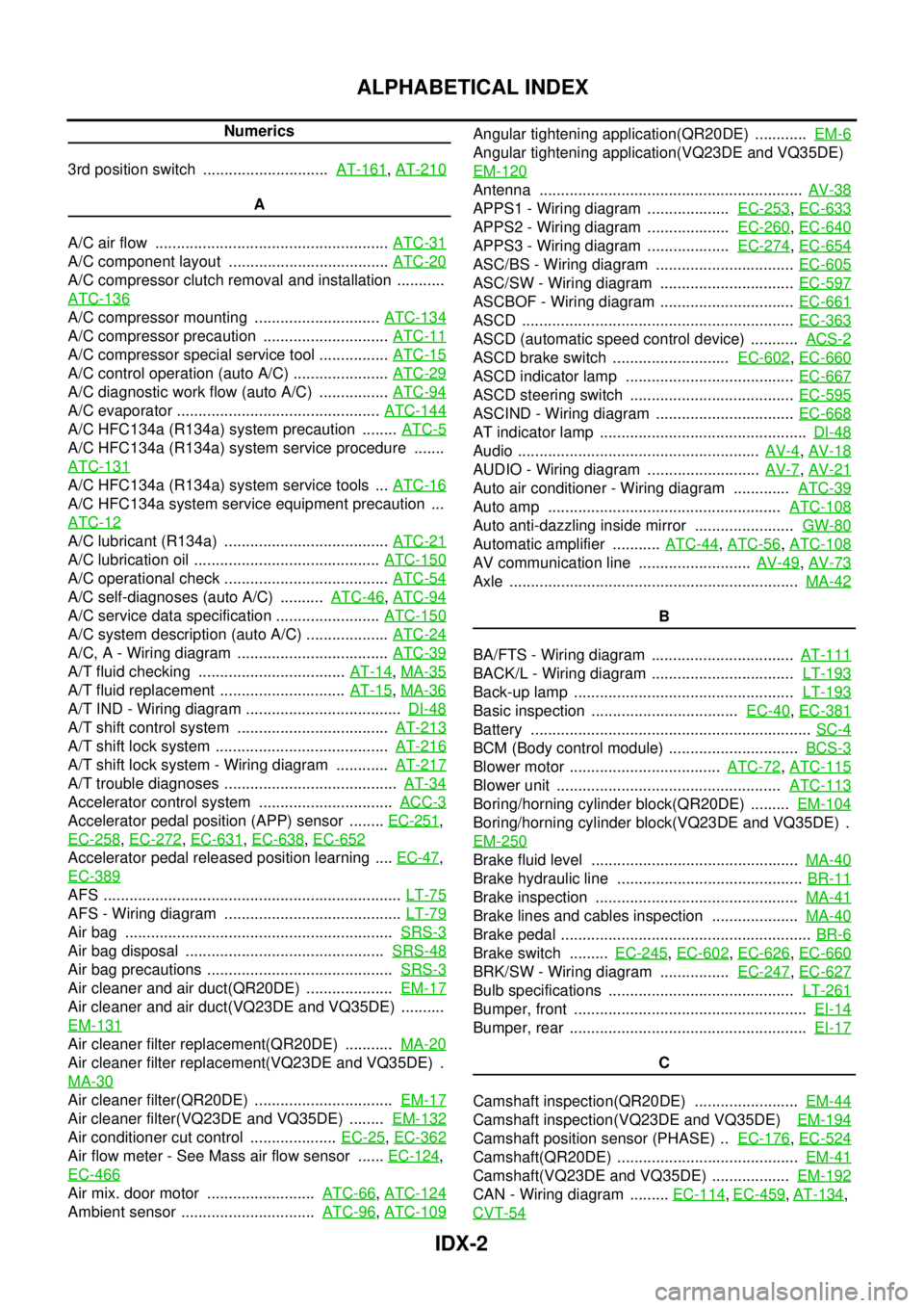
ALPHABETICAL INDEX
Numerics
3rd position switch ............................. AT-161
, AT-210
A
A/C air flow ...................................................... ATC-31
A/C component layout ..................................... ATC-20
A/C compressor clutch removal and installation ...........
ATC-136
A/C compressor mounting ............................. ATC-134
A/C compressor precaution ............................. ATC-11
A/C compressor special service tool ................ ATC-15
A/C control operation (auto A/C) ...................... ATC-29
A/C diagnostic work flow (auto A/C) ................ ATC-94
A/C evaporator ............................................... ATC-144
A/C HFC134a (R134a) system precaution ........ ATC-5
A/C HFC134a (R134a) system service procedure .......
ATC-131
A/C HFC134a (R134a) system service tools ... ATC-16
A/C HFC134a system service equipment precaution ...
ATC-12
A/C lubricant (R134a) ...................................... ATC-21
A/C lubrication oil ........................................... ATC-150
A/C operational check ...................................... ATC-54
A/C self-diagnoses (auto A/C) .......... ATC-46, ATC-94
A/C service data specification ........................ ATC-150
A/C system description (auto A/C) ................... ATC-24
A/C, A - Wiring diagram ................................... ATC-39
A/T fluid checking .................................. AT-14, MA-35
A/T fluid replacement ............................. AT-15, MA-36
A/T IND - Wiring diagram .................................... DI-48
A/T shift control system ................................... AT-213
A/T shift lock system ........................................ AT-216
A/T shift lock system - Wiring diagram ............ AT-217
A/T trouble diagnoses ........................................ AT-34
Accelerator control system ............................... ACC-3
Accelerator pedal position (APP) sensor ........ EC-251,
EC-258
, EC-272, EC-631, EC-638, EC-652
Accelerator pedal released position learning .... EC-47,
EC-389
AFS ..................................................................... LT-75
AFS - Wiring diagram ......................................... LT-79
Air bag .............................................................. SRS-3
Air bag disposal .............................................. SRS-48
Air bag precautions ........................................... SRS-3
Air cleaner and air duct(QR20DE) .................... EM-17
Air cleaner and air duct(VQ23DE and VQ35DE) ..........
EM-131
Air cleaner filter replacement(QR20DE) ........... MA-20
Air cleaner filter replacement(VQ23DE and VQ35DE) .
MA-30
Air cleaner filter(QR20DE) ................................ EM-17
Air cleaner filter(VQ23DE and VQ35DE) ........ EM-132
Air conditioner cut control .................... EC-25, EC-362
Air flow meter - See Mass air flow sensor ...... EC-124,
EC-466
Air mix. door motor ......................... ATC-66, ATC-124
Ambient sensor ............................... ATC-96, ATC-109
Angular tightening application(QR20DE) ............ EM-6
Angular tightening application(VQ23DE and VQ35DE)
EM-120
Antenna ............................................................. AV-38
APPS1 - Wiring diagram ................... EC-253, EC-633
APPS2 - Wiring diagram ................... EC-260, EC-640
APPS3 - Wiring diagram ................... EC-274, EC-654
ASC/BS - Wiring diagram ................................ EC-605
ASC/SW - Wiring diagram ............................... EC-597
ASCBOF - Wiring diagram ............................... EC-661
ASCD ............................................................... EC-363
ASCD (automatic speed control device) ........... ACS-2
ASCD brake switch ........................... EC-602, EC-660
ASCD indicator lamp ....................................... EC-667
ASCD steering switch ...................................... EC-595
ASCIND - Wiring diagram ................................ EC-668
AT indicator lamp ................................................ DI-48
Audio ........................................................ AV-4, AV-18
AUDIO - Wiring diagram .......................... AV-7, AV-21
Auto air conditioner - Wiring diagram ............. ATC-39
Auto amp ...................................................... ATC-108
Auto anti-dazzling inside mirror ....................... GW-80
Automatic amplifier ........... ATC-44, ATC-56, ATC-108
AV communication line .......................... AV-49, AV-73
Axle ................................................................... MA-42
B
BA/FTS - Wiring diagram ................................. AT-111
BACK/L - Wiring diagram ................................. LT-193
Back-up lamp ................................................... LT-193
Basic inspection .................................. EC-40, EC-381
Battery ................................................................. SC-4
BCM (Body control module) .............................. BCS-3
Blower motor ................................... ATC-72, ATC-115
Blower unit .................................................... ATC-113
Boring/horning cylinder block(QR20DE) ......... EM-104
Boring/horning cylinder block(VQ23DE and VQ35DE) .
EM-250
Brake fluid level ................................................ MA-40
Brake hydraulic line ........................................... BR-11
Brake inspection ............................................... MA-41
Brake lines and cables inspection .................... MA-40
Brake pedal .......................................................... BR-6
Brake switch ......... EC-245, EC-602, EC-626, EC-660
BRK/SW - Wiring diagram ................ EC-247, EC-627
Bulb specifications ........................................... LT-261
Bumper, front ...................................................... EI-14
Bumper, rear ....................................................... EI-17
C
Camshaft inspection(QR20DE) ........................ EM-44
Camshaft inspection(VQ23DE and VQ35DE) EM-194
Camshaft position sensor (PHASE) .. EC-176, EC-524
Camshaft(QR20DE) .......................................... EM-41
Camshaft(VQ23DE and VQ35DE) .................. EM-192
CAN - Wiring diagram ......... EC-114, EC-459, AT-134,
CVT-54
Page 2655 of 3502
![NISSAN TEANA 2003 Service Manual TROUBLE DIAGNOSIS
LAN-51
[CAN]
C
D
E
F
G
H
I
J
L
MA
B
LAN
CAN Communication Signal ChartBKS002DP
Refer to LAN-15, "How to Use CAN Communication Signal Chart" for how to use CAN communication signal NISSAN TEANA 2003 Service Manual TROUBLE DIAGNOSIS
LAN-51
[CAN]
C
D
E
F
G
H
I
J
L
MA
B
LAN
CAN Communication Signal ChartBKS002DP
Refer to LAN-15, "How to Use CAN Communication Signal Chart" for how to use CAN communication signal](/manual-img/5/57392/w960_57392-2654.png)
TROUBLE DIAGNOSIS
LAN-51
[CAN]
C
D
E
F
G
H
I
J
L
MA
B
LAN
CAN Communication Signal ChartBKS002DP
Refer to LAN-15, "How to Use CAN Communication Signal Chart" for how to use CAN communication signal
chart.
TYPE 1/TYPE 2
NOTE:
Refer to LAN-41, "
Abbreviation List" for the abbreviations of the connecting units.
T: Transmit R: Receive
Signals
ECM
ADP
BCM
M&A
DISP
TCM
ABS
IPDM-E
A/C compressor request signal T R
Accelerator pedal position signal T R
Closed throttle position signal T R
Cooling fan speed request signal T R
Engine and A/T integrated control signalTR
RT
Engine coolant temperature signal T R
Engine speed signal T R
Fuel consumption monitor signalTR
TR
Malfunction indicator signal T R
Wide open throttle position signal T R
A/C switch signal R T
Blower fan motor switch signal R T
Buzzer output signal T R
Door switch signal R T R R
Front fog light request signal T R R
Front wiper request signal T R
High beam request signal T R R
Ignition switch signal R T R
Key fob door unlock signal R T
Key fob ID signal R T
Key switch signal R T
Low beam request signal T R
Oil pressure switch signalRT
TR
Position light request signal T R R
Rear fog status signal T R
Rear window defogger switch signal T R
Sleep wake up signal T R R
Turn indicator signal T R
3rd position switch signal T R
A/C switch/indicator signalRT
TR
Distance to empty signal T R
Fuel level low warning signal T R
Stop lamp switch signal T R
Page 2656 of 3502
![NISSAN TEANA 2003 Service Manual LAN-52
[CAN]
TROUBLE DIAGNOSIS
*: P range only
TYPE 3
NOTE:
Refer to LAN-41, "
Abbreviation List" for the abbreviations of the connecting units.
T: Transmit R: Receive Vehicle speed signalRT
RRR NISSAN TEANA 2003 Service Manual LAN-52
[CAN]
TROUBLE DIAGNOSIS
*: P range only
TYPE 3
NOTE:
Refer to LAN-41, "
Abbreviation List" for the abbreviations of the connecting units.
T: Transmit R: Receive Vehicle speed signalRT
RRR](/manual-img/5/57392/w960_57392-2655.png)
LAN-52
[CAN]
TROUBLE DIAGNOSIS
*: P range only
TYPE 3
NOTE:
Refer to LAN-41, "
Abbreviation List" for the abbreviations of the connecting units.
T: Transmit R: Receive Vehicle speed signalRT
RRR T R
A/T CHECK indicator lamp signal R T
A/T position indicator lamp signal
R
*RT
Output shaft revolution signal R T
ABS warning lamp signal R T
Brake warning lamp signal R T
Front wiper stop position signal R T
High beam status signal R T
Low beam status signal R T
Rear window defogger control signal R R R TSignals
ECM
ADP
BCM
M&A
DISP
TCM
ABS
IPDM-E
SignalsECM
ADP
AFS
BCM
I-KEY
M&A
STRG
DISP
TCM
ABS
IPDM-E
A/C compressor request signal TR
Accelerator pedal position signal T R R
Closed throttle position signal T R
Cooling fan speed request signal TR
Engine and A/T integrated control signalTR
RT
Engine coolant temperature signal T R
Engine speed signal T R R
Fuel consumption monitor signalTR
TR
Malfunction indicator signal T R
Wide open throttle position signal T R
A/C switch signal R T
Blower fan motor switch signal R T
Buzzer output signalTR
TR
Door lock/unlock status signal T R
Door switch signal R T R R R
Front fog light request signal T R R
Front wiper request signal T R
High beam request signal T R R
Ignition switch signal R T R
Key fob door unlock signal R T
Key fob ID signal R T
Key switch signal R T
Page 2658 of 3502
![NISSAN TEANA 2003 Service Manual LAN-54
[CAN]
TROUBLE DIAGNOSIS
TYPE 4
NOTE:
Refer to LAN-41, "
Abbreviation List" for the abbreviations of the connecting units.
T: Transmit R: Receive
Signals
ECM
ADP
AFS
BCM
I-KEY
M&A
STRG
DIS NISSAN TEANA 2003 Service Manual LAN-54
[CAN]
TROUBLE DIAGNOSIS
TYPE 4
NOTE:
Refer to LAN-41, "
Abbreviation List" for the abbreviations of the connecting units.
T: Transmit R: Receive
Signals
ECM
ADP
AFS
BCM
I-KEY
M&A
STRG
DIS](/manual-img/5/57392/w960_57392-2657.png)
LAN-54
[CAN]
TROUBLE DIAGNOSIS
TYPE 4
NOTE:
Refer to LAN-41, "
Abbreviation List" for the abbreviations of the connecting units.
T: Transmit R: Receive
Signals
ECM
ADP
AFS
BCM
I-KEY
M&A
STRG
DISP
TCM
ABS
IPDM-E
A/C compressor request signal TR
Accelerator pedal position signal T R R
ASCD CRUISE lamp signal T R
ASCD SET lamp signal T R
Closed throttle position signal T R
Cooling fan speed request signal TR
Engine and CVT integrated control signalTR
RT
Engine coolant temperature signal T R
Engine speed signal T R R R
Fuel consumption monitor signalTR
TR
Malfunction indicator signal T R
Wide open throttle position signal T R
A/C switch signal R T
Blower fan motor switch signal R T
Buzzer output signalTR
TR
Door lock/unlock status signal T R
Door switch signal R T R R R
Front fog light request signal T R R
Front wiper request signal T R
High beam request signal T R R
Ignition switch signal R T R
Key fob door unlock signal R T
Key fob ID signal R T
Key switch signal R T
Low beam request signal T R
Oil pressure switch signalRT
TR
Position light request signal T R R
Rear fog status signal T R
Rear window defogger switch signal T R
Sleep wake up signalTRR R
RT
Turn indicator signal T R
Door lock/unlock/trunk open request signal R T
Hazard warning lamp request signal R T
Ignition knob switch signal R T
Key warning signal T R
Page 2984 of 3502

MA-6
GENERAL MAINTENANCE
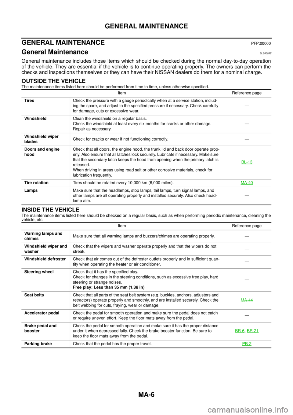
GENERAL MAINTENANCEPFP:00000
General MaintenanceBLS0005E
General maintenance includes those items which should be checked during the normal day-to-day operation
of the vehicle. They are essential if the vehicle is to continue operating properly. The owners can perform the
checks and inspections themselves or they can have their NISSAN dealers do them for a nominal charge.
OUTSIDE THE VEHICLE
The maintenance items listed here should be performed from time to time, unless otherwise specified.
INSIDE THE VEHICLE
The maintenance items listed here should be checked on a regular basis, such as when performing periodic maintenance, cleaning the
vehicle, etc.Item Reference page
TiresCheck the pressure with a gauge periodically when at a service station, includ-
ing the spare, and adjust to the specified pressure if necessary. Check carefully
for damage, cuts or excessive wear.—
WindshieldClean the windshield on a regular basis.
Check the windshield at least every six months for cracks or other damage.
Repair as necessary.—
Windshield wiper
bladesCheck for cracks or wear if not functioning correctly. —
Doors and engine
hoodCheck that all doors, the engine hood, the trunk lid and back door operate prop-
erly. Also ensure that all latches lock securely. Lubricate if necessary. Make sure
that the secondary latch keeps the hood from opening when the primary latch is
released.
When driving in areas using road salt or other corrosive materials, check for
lubrication frequently.BL-13
Tire rotationTires should be rotated every 10,000 km (6,000 miles).MA-40
LampsMake sure that the headlamps, stop lamps, tail lamps, turn signal lamps, and
other lamps are all operating properly and installed securely. Also check head-
lamp aim.—
Item Reference page
Warning lamps and
chimesMake sure that all warning lamps and buzzers/chimes are operating properly. —
Windshield wiper and
washerCheck that the wipers and washer operate properly and that the wipers do not
streak.—
Windshield defrosterCheck that air comes out of the defroster outlets properly and in sufficient quan-
tity when operating the heater or air conditioner.—
Steering wheelCheck that it has the specified play.
Check for changes in the steering conditions, such as excessive free play, hard
steering or strange noises.
Free play: Less than 35 mm (1.38 in)—
Seat beltsCheck that all parts of the seat belt system (e.g. buckles, anchors, adjusters and
retractors) operate properly and smoothly, and are installed securely. Check the
belt webbing for cuts, fraying, wear or damage.MA-44
Accelerator pedalCheck the pedal for smooth operation and make sure the pedal does not catch
or require uneven effort. Keep the floor mats away from the pedal.—
Brake pedal and
boosterCheck the pedal for smooth operation and make sure it has the proper distance
under it when depressed fully. Check the brake booster function. Be sure to
keep the floor mats away from the pedal.BR-6
, BR-21
Parking brakeCheck that the pedal has the proper travel.PB-2
Page 3097 of 3502

HARNESS
PG-63
C
D
E
F
G
H
I
J
L
MA
B
PG
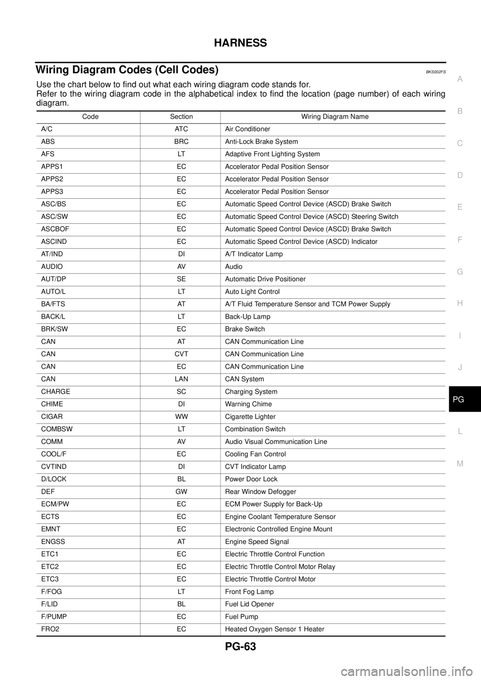
Wiring Diagram Codes (Cell Codes) BKS002FS
Use the chart below to find out what each wiring diagram code stands for.
Refer to the wiring diagram code in the alphabetical index to find the location (page number) of each wiring
diagram.
Code Section Wiring Diagram Name
A/C ATC Air Conditioner
ABS BRC Anti-Lock Brake System
AFS LT Adaptive Front Lighting System
APPS1 EC Accelerator Pedal Position Sensor
APPS2 EC Accelerator Pedal Position Sensor
APPS3 EC Accelerator Pedal Position Sensor
ASC/BS EC Automatic Speed Control Device (ASCD) Brake Switch
ASC/SW EC Automatic Speed Control Device (ASCD) Steering Switch
ASCBOF EC Automatic Speed Control Device (ASCD) Brake Switch
ASCIND EC Automatic Speed Control Device (ASCD) Indicator
AT/IND DI A/T Indicator Lamp
AUDIO AV Audio
AUT/DP SE Automatic Drive Positioner
AUTO/L LT Auto Light Control
BA/FTS AT A/T Fluid Temperature Sensor and TCM Power Supply
BACK/L LT Back-Up Lamp
BRK/SW EC Brake Switch
CAN AT CAN Communication Line
CAN CVT CAN Communication Line
CAN EC CAN Communication Line
CAN LAN CAN System
CHARGE SC Charging System
CHIME DI Warning Chime
CIGAR WW Cigarette Lighter
COMBSW LT Combination Switch
COMM AV Audio Visual Communication Line
COOL/F EC Cooling Fan Control
CVTIND DI CVT Indicator Lamp
D/LOCK BL Power Door Lock
DEF GW Rear Window Defogger
ECM/PW EC ECM Power Supply for Back-Up
ECTS EC Engine Coolant Temperature Sensor
EMNT EC Electronic Controlled Engine Mount
ENGSS AT Engine Speed Signal
ETC1 EC Electric Throttle Control Function
ETC2 EC Electric Throttle Control Motor Relay
ETC3 EC Electric Throttle Control Motor
F/FOG LT Front Fog Lamp
F/LID BL Fuel Lid Opener
F/PUMP EC Fuel Pump
FRO2 EC Heated Oxygen Sensor 1 Heater