Page 1340 of 3502
![NISSAN TEANA 2003 Service Manual EC-58
[QR]
TROUBLE DIAGNOSIS
DTC Inspection Priority ChartBBS005C0
If some DTCs are displayed at the same time, perform inspections one by one based on the following priority
chart.
NOTE:
If DTC U10](/manual-img/5/57392/w960_57392-1339.png "NISSAN TEANA 2003 Service Manual EC-58
[QR]
TROUBLE DIAGNOSIS
DTC Inspection Priority ChartBBS005C0
If some DTCs are displayed at the same time, perform inspections one by one based on the following priority
chart.
NOTE:
If DTC U10")
EC-58
[QR]
TROUBLE DIAGNOSIS
DTC Inspection Priority ChartBBS005C0
If some DTCs are displayed at the same time, perform inspections one by one based on the following priority
chart.
NOTE:
If DTC U1000 and/or U1001 is displayed with other DTC, first perform the trouble diagnosis for DTC
U1000 and U1001. Refer to EC-113, "
DTC U1000, U1001 CAN COMMUNICATION LINE" .
Priority Detected items (DTC)
1
�U1000 U1001 CAN communication line
�P0102 P0103 Mass air flow sensor
�P0117 P0118 Engine coolant temperature sensor
�P0122 P0123 P0222 P0223 P1225 P1226 P2135 Throttle position sensor
�P0327 P0328 Knock sensor
�P0335 Crankshaft position sensor (POS)
�P0340 Camshaft position sensor (PHASE)
�P0500 Vehicle speed sensor
�P0605 ECM
�P1229 Sensor power supply
�P1610-P1615 NATS
�P1706 Park/Neutral position (PNP) switch
�P2122 P2123 P2127 P2128 P2138 Accelerator pedal position sensor
2
�P0132 P0134 Heated oxygen sensor 1
�P0550 Power steering pressure sensor
�P1065 ECM power supply
�P1122 Electric throttle control function
�P1124 P1126 Throttle control motor relay
�P1128 Throttle control motor
�P1720 Vehicle speed sensor
�P1805 Brake switch
3
�P0011 Intake valve timing control
�P1121 Electric throttle control actuator
�P1217 Engine over temperature (OVERHEAT)
Page 1341 of 3502
![NISSAN TEANA 2003 Service Manual TROUBLE DIAGNOSIS
EC-59
[QR]
C
D
E
F
G
H
I
J
K
L
MA
EC
Fail-Safe ChartBBS005C1
When the DTC listed bellow is detected, the ECM enters fail-safe mode and the MI lights up.
When there is an open circu](/manual-img/5/57392/w960_57392-1340.png "NISSAN TEANA 2003 Service Manual TROUBLE DIAGNOSIS
EC-59
[QR]
C
D
E
F
G
H
I
J
K
L
MA
EC
Fail-Safe ChartBBS005C1
When the DTC listed bellow is detected, the ECM enters fail-safe mode and the MI lights up.
When there is an open circu")
TROUBLE DIAGNOSIS
EC-59
[QR]
C
D
E
F
G
H
I
J
K
L
MA
EC
Fail-Safe ChartBBS005C1
When the DTC listed bellow is detected, the ECM enters fail-safe mode and the MI lights up.
When there is an open circuit on MI circuit, the ECM can not warn the driver by lighting up MI when there is
trouble on engine control system. Therefore, when Electrical controlled throttle and part of the ECM related
diagnoses are continuously detected as NG for 5-trips, ECM warns the driver that engine control system has
trouble and MI circuit is open by means of operating fail-safe function.
The fail-safe function also operates when above diagnoses except MI circuit are detected and demands the
driver to repair the trouble.
DTC No. Detected items Engine operating condition in fail-safe mode
P0102
P0103Mass air flow sensor circuit Engine speed will not rise more than 2,400 rpm due to the fuel cut.
P0122
P0123
P0221
P0222
P2135Throttle position sensor The ECM controls the electric throttle control actuator in regulating the throttle opening in
order for the idle position to be within +10 degrees.
The ECM regulates the opening speed of the throttle valve to be slower than the normal
condition.
So, the acceleration will be poor.
P1121 Electric throttle control
actuator(When electric throttle control actuator does not function properly due to the return spring
malfunction:)
ECM controls the electric throttle actuator by regulating the throttle opening around the
idle position. The engine speed will not rise more than 2,000 rpm.
(When throttle valve opening angle in fail-safe mode is not in specified range:)
ECM controls the electric throttle control actuator by regulating the throttle opening to 20
degrees or less.
(ECM detect the throttle valve is stuck open:)
While the vehicle is driving, it slows down gradually by fuel cut. After the vehicle stops, the
engine stalls.
The engine can restart in N or P position, and engine speed will not exceed 1,000 rpm or
more.
P1122 Electric throttle control
functionECM stops the electric throttle control actuator control, throttle valve is maintained at a
fixed opening (approx. 5 degrees) by the return spring.
P1124
P1126Throttle control motor relay ECM stops the electric throttle control actuator control, throttle valve is maintained at a
fixed opening (approx. 5 degrees) by the return spring.
P1128 Throttle control motor ECM stops the electric throttle control actuator control, throttle valve is maintained at a
fixed opening (approx. 5 degrees) by the return spring.
P1229 Sensor power supply ECM stops the electric throttle control actuator control, throttle valve is maintained at a
fixed opening (approx. 5 degrees) by the return spring.
P1805 Brake switchECM controls the electric throttle control actuator by regulating the throttle opening to a
small range.
Vehicle condition Driving condition
When engine is idling Normal
When accelerating Poor acceleration
P2122
P2123
P2127
P2128
P2138Accelerator pedal position
sensorThe ECM controls the electric throttle control actuator in regulating the throttle opening in
order for the idle position to be within +10 degrees.
The ECM regulates the opening speed of the throttle valve to be slower than the normal
condition.
So, the acceleration will be poor.
Engine operating condition in fail-safe mode Engine speed will not rise more than 2,500 rpm due to the fuel cut
Page 1342 of 3502
![NISSAN TEANA 2003 Service Manual EC-60
[QR]
TROUBLE DIAGNOSIS
Symptom Matrix ChartBBS005C2
SYSTEM — BASIC ENGINE CONTROL SYSTEM
SYMPTOM
Reference
page
HARD/NO START/RESTART (EXCP. HA)
ENGINE STALL
HESITATION/SURGING/FLAT SPOT
SP](/manual-img/5/57392/w960_57392-1341.png "NISSAN TEANA 2003 Service Manual EC-60
[QR]
TROUBLE DIAGNOSIS
Symptom Matrix ChartBBS005C2
SYSTEM — BASIC ENGINE CONTROL SYSTEM
SYMPTOM
Reference
page
HARD/NO START/RESTART (EXCP. HA)
ENGINE STALL
HESITATION/SURGING/FLAT SPOT
SP")
EC-60
[QR]
TROUBLE DIAGNOSIS
Symptom Matrix ChartBBS005C2
SYSTEM — BASIC ENGINE CONTROL SYSTEM
SYMPTOM
Reference
page
HARD/NO START/RESTART (EXCP. HA)
ENGINE STALL
HESITATION/SURGING/FLAT SPOT
SPARK KNOCK/DETONATION
LACK OF POWER/POOR ACCELERATION
HIGH IDLE/LOW IDLE
ROUGH IDLE/HUNTING
IDLING VIBRATION
SLOW/NO RETURN TO IDLE
OVERHEATS/WATER TEMPERATURE HIGH
EXCESSIVE FUEL CONSUMPTION
EXCESSIVE OIL CONSUMPTION
BATTERY DEAD (UNDER CHARGE)
Warranty symptom code AA AB AC AD AE AF AG AH AJ AK AL AM HA
Fuel Fuel pump circuit 11232 22 3 2EC-295
Fuel pressure regulator system334444444 4EC-49
Fuel injector circuit 11232 22 2EC-289
Evaporative emission system 334444444 4EC-27
Air Positive crankcase ventilation sys-
tem334444444 41EC-30
Incorrect idle speed adjustment 33 1111 1EC-40
Electric throttle control actuator 112332222 2 2EC-197
,
EC-200
,
EC-207
,
EC-213
IgnitionIncorrect ignition timing adjustment33111 11 1EC-40
Ignition circuit 11222 22 2EC-329
Main power supply and ground circuit 22333 33 23EC-106
Mass air flow sensor circuit 11222 22 2EC-124
Engine coolant temperature sensor circuit 11222322312EC-131
Throttle position sensor circuit 12 22222 2EC-136
,
EC-157
,
EC-229
,
EC-231
,
EC-265
Accelerator pedal position sensor circuit3212 2EC-233
,
EC-251
,
EC-258
,
EC-272
Heated oxygen sensor 1 circuit 1232 22 2EC-143
,
EC-150
,
EC-301
Knock sensor circuit 2 2 3EC-164
Crankshaft position sensor (POS) circuit 2 2EC-169
Camshaft position sensor (PHASE) circuit 2 2EC-176
Vehicle speed signal circuit 2 3 3 3EC-183
Power steering pressure sensor circuit 2 3333EC-185
Page 1343 of 3502
TROUBLE DIAGNOSIS
EC-61
[QR]
C
D
E
F
G
H
I
J
K
L
MA
EC
1 - 6: The numbers refer to the order of inspection.
(continued on next page)ECM 22333333333EC-190
,
EC-193
Intake valve timing control solenoid valve cir-
cuit332 13223 3EC-116
PNP switch circuit 3 33333 3EC-238
Refrigerant pressure sensor circuit 2 3 3 3 3 4EC-339
Electrical load signal circuit 3 3 3 3EC-280
Air conditioner circuit223333333 3 2AT C - 3 4
ABS actuator and electric unit (control unit) 4BRC-8
SYMPTOM
Reference
page
HARD/NO START/RESTART (EXCP. HA)
ENGINE STALL
HESITATION/SURGING/FLAT SPOT
SPARK KNOCK/DETONATION
LACK OF POWER/POOR ACCELERATION
HIGH IDLE/LOW IDLE
ROUGH IDLE/HUNTING
IDLING VIBRATION
SLOW/NO RETURN TO IDLE
OVERHEATS/WATER TEMPERATURE HIGH
EXCESSIVE FUEL CONSUMPTION
EXCESSIVE OIL CONSUMPTION
BATTERY DEAD (UNDER CHARGE)
Warranty symptom code AA AB AC AD AE AF AG AH AJ AK AL AM HA
Page 1344 of 3502
![NISSAN TEANA 2003 Service Manual EC-62
[QR]
TROUBLE DIAGNOSIS
SYSTEM — ENGINE MECHANICAL & OTHER
SYMPTOM
Reference
page
HARD/NO START/RESTART (EXCP. HA)
ENGINE STALL
HESITATION/SURGING/FLAT SPOT
SPARK KNOCK/DETONATION
LACK OF PO](/manual-img/5/57392/w960_57392-1343.png "NISSAN TEANA 2003 Service Manual EC-62
[QR]
TROUBLE DIAGNOSIS
SYSTEM — ENGINE MECHANICAL & OTHER
SYMPTOM
Reference
page
HARD/NO START/RESTART (EXCP. HA)
ENGINE STALL
HESITATION/SURGING/FLAT SPOT
SPARK KNOCK/DETONATION
LACK OF PO")
EC-62
[QR]
TROUBLE DIAGNOSIS
SYSTEM — ENGINE MECHANICAL & OTHER
SYMPTOM
Reference
page
HARD/NO START/RESTART (EXCP. HA)
ENGINE STALL
HESITATION/SURGING/FLAT SPOT
SPARK KNOCK/DETONATION
LACK OF POWER/POOR ACCELERATION
HIGH IDLE/LOW IDLE
ROUGH IDLE/HUNTING
IDLING VIBRATION
SLOW/NO RETURN TO IDLE
OVERHEATS/WATER TEMPERATURE HIGH
EXCESSIVE FUEL CONSUMPTION
EXCESSIVE OIL CONSUMPTION
BATTERY DEAD (UNDER CHARGE)
Warranty symptom code AA AB AC AD AE AF AG AH AJ AK AL AM HA
Fuel Fuel tank
5
5FL-8
Fuel piping 5 5 5 5 5 5EM-34
Vapor lock—
Valve deposit
5 555 55 5—
Poor fuel (Heavy weight gaso-
line, Low octane)—
Air Air duct
55555 5EM-17
Air cleaner
Air leakage from air duct
(Mass air flow sensor —electric
throttle control actuator)
5555
Electric throttle control actuator
EM-19
Air leakage from intake manifold/
Collector/Gasket
Cranking Battery
111111 11SC-4
Alternator circuitSC-27
Starter circuit 3SC-14
Signal plate/Flywheel/Drive plate 6EM-81
PNP switch 4AT- 1 6 1
Engine Cylinder head
55555 55 5EM-65
Cylinder head gasket 4 3
Cylinder block
66666 66 64
EM-81
Piston
Piston ring
Connecting rod
Bearing
Crankshaft
Va l v e
mecha-
nismTiming chain
55555 55 5EM-53
CamshaftEM-41
Intake valve timing controlEM-53
Intake valve
3EM-65
Exhaust valve
Page 1346 of 3502
EC-64
[QR]
TROUBLE DIAGNOSIS
Engine Control Component Parts LocationBBS005C3
PBIB3283E
Page 1355 of 3502
![NISSAN TEANA 2003 Service Manual TROUBLE DIAGNOSIS
EC-73
[QR]
C
D
E
F
G
H
I
J
K
L
MA
EC
2R/LHeated oxygen sensor 2
heater[Engine is running]
�Engine speed: Below 3,800 rpm after the
following conditions are met
–Engine: After w](/manual-img/5/57392/w960_57392-1354.png "NISSAN TEANA 2003 Service Manual TROUBLE DIAGNOSIS
EC-73
[QR]
C
D
E
F
G
H
I
J
K
L
MA
EC
2R/LHeated oxygen sensor 2
heater[Engine is running]
�Engine speed: Below 3,800 rpm after the
following conditions are met
–Engine: After w")
TROUBLE DIAGNOSIS
EC-73
[QR]
C
D
E
F
G
H
I
J
K
L
MA
EC
2R/LHeated oxygen sensor 2
heater[Engine is running]
�Engine speed: Below 3,800 rpm after the
following conditions are met
–Engine: After warming up
–Keeping the engine speed between 3,500
and 4,000 rpm for 1 minute and at idle for
1 minute under no load0 - 1.0V
[Ignition switch: ON]
�Engine stopped
[Engine is running]
�Engine speed: Above 3,800 rpmBATTERY VOLTAGE
(11 - 14V)
3 G/WThrottle control motor relay
power supply[Ignition switch: ON]BATTERY VOLTAGE
(11 - 14V)
4LThrottle control motor
(Close)[Ignition switch: ON]
�Engine stopped
�Shift lever: D
�Accelerator pedal: Fully released0 - 14V
5YThrottle control motor
(Open)[Ignition switch: ON]
�Engine stopped
�Shift lever: D
�Accelerator pedal: Fully depressed0 - 14V
12 WPower steering pressure
sensor[Engine is running]
�Steering wheel: Being turned0.5 - 4.0V
[Engine is running]
�Steering wheel: Not being turned0.4 - 0.8V
13 WCrankshaft position
sensor (POS)[Engine is running]
�Warm-up condition
�Idle speed
NOTE:
The pulse cycle changes depending on
rpm at idleApproximately 3.0V
[Engine is running]
�Engine speed: 2,000 rpmApproximately 3.0V TERMI-
NAL
NO.WIRE
COLORITEM CONDITION DATA (DC Voltage)
PBIB1104E
PBIB1105E
PBIB0527E
PBIB0528E
Page 1356 of 3502
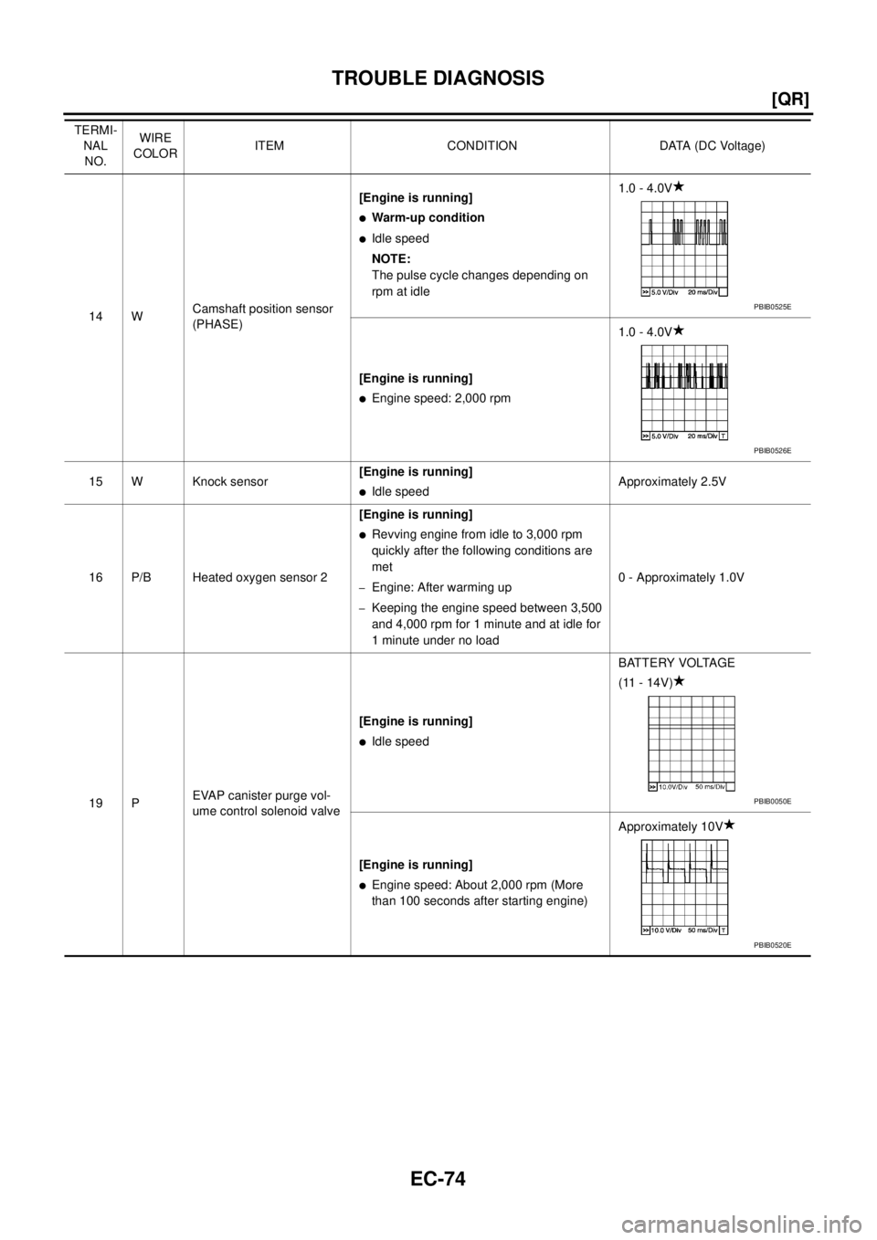
EC-74
[QR]
TROUBLE DIAGNOSIS
14 WCamshaft position sensor
(PHASE)[Engine is running]
�Warm-up condition
�Idle speed
NOTE:
The pulse cycle changes depending on
rpm at idle1.0 - 4.0V
[Engine is running]
�Engine speed: 2,000 rpm1.0 - 4.0V
15 W Knock sensor[Engine is running]
�Idle speedApproximately 2.5V
16 P/B Heated oxygen sensor 2[Engine is running]
�Revving engine from idle to 3,000 rpm
quickly after the following conditions are
met
–Engine: After warming up
–Keeping the engine speed between 3,500
and 4,000 rpm for 1 minute and at idle for
1 minute under no load0 - Approximately 1.0V
19 PEVAP canister purge vol-
ume control solenoid valve[Engine is running]
�Idle speedBATTERY VOLTAGE
(11 - 14V)
[Engine is running]
�Engine speed: About 2,000 rpm (More
than 100 seconds after starting engine)Approximately 10V TERMI-
NAL
NO.WIRE
COLORITEM CONDITION DATA (DC Voltage)
PBIB0525E
PBIB0526E
PBIB0050E
PBIB0520E
![NISSAN TEANA 2003 Service Manual TROUBLE DIAGNOSIS
EC-61
[QR]
C
D
E
F
G
H
I
J
K
L
MA
EC
1 - 6: The numbers refer to the order of inspection.
(continued on next page)ECM 22333333333EC-190
,
EC-193
Intake valve timing control soleno](/manual-img/5/57392/w960_57392-1342.png "NISSAN TEANA 2003 Service Manual TROUBLE DIAGNOSIS
EC-61
[QR]
C
D
E
F
G
H
I
J
K
L
MA
EC
1 - 6: The numbers refer to the order of inspection.
(continued on next page)ECM 22333333333EC-190
,
EC-193
Intake valve timing control soleno")
![NISSAN TEANA 2003 Service Manual EC-64
[QR]
TROUBLE DIAGNOSIS
Engine Control Component Parts LocationBBS005C3
PBIB3283E](/manual-img/5/57392/w960_57392-1345.png "NISSAN TEANA 2003 Service Manual EC-64
[QR]
TROUBLE DIAGNOSIS
Engine Control Component Parts LocationBBS005C3
PBIB3283E")