Page 2335 of 3502
ENGINE ASSEMBLY
EM-227
[VQ]
C
D
E
F
G
H
I
J
K
L
MA
EM
Summary of the inspection items:
* Transmission/transaxle/CVT fluid. power steering fluid, brake fluid, etc.Item Before starting engine Engine running After engine stopped
Engine coolant Level Leakage Level
Engine oil Level Leakage Level
Other oils and fluid* Level Leakage Level
Fuel Leakage Leakage Leakage
Exhaust gases — Leakage —
Page 2338 of 3502
![NISSAN TEANA 2003 Service Manual EM-230
[VQ]
CYLINDER BLOCK
�A widely use engine stand can be used.
CAUTION:
Use engine stand that has a load capacity [approximately
220 kg (441 lb) or more] large enough for supporting the
engine w](/manual-img/5/57392/w960_57392-2337.png "NISSAN TEANA 2003 Service Manual EM-230
[VQ]
CYLINDER BLOCK
�A widely use engine stand can be used.
CAUTION:
Use engine stand that has a load capacity [approximately
220 kg (441 lb) or more] large enough for supporting the
engine w")
EM-230
[VQ]
CYLINDER BLOCK
�A widely use engine stand can be used.
CAUTION:
Use engine stand that has a load capacity [approximately
220 kg (441 lb) or more] large enough for supporting the
engine weight.
NOTE:
This example is engine stand for holding at transaxle mount-
ing side with drive plate removed.
5. Drain engine oil. Refer to LU-21, "
Changing Engine Oil" .
6. Drain engine coolant by removing water drain plugs from cylin-
der block both sides at “A” and “D” and cylinder block front side
at “B” as shown in the figure.
NOTE:
Water drain plug at the right bank side for VQ35DE is also used
as a connector of water pipe for oil cooler. Refer to LU-23, "
OIL
COOLER (VQ35DE)" .
7. Remove drive plate. Fix crankshaft pulley with pulley holder [SST: KV10109300], and remove mounting
bolts.
�Loosen mounting bolts in diagonal order.
CAUTION:
�Do not disassemble drive plate.
�Do not place drive plate with signal plate facing down.
�When handling signal plate, take care not to damage or
scratch it.
�Handle signal plate in a manner that prevents it from
becoming magnetized.
8. Remove cylinder head. Refer to EM-210, "
CYLINDER HEAD" .
9. Remove knock sensor.
CAUTION:
Carefully handle sensor avoiding shocks.
PBIC0085E
PBIC2487E
SEM760G
Page 2341 of 3502
CYLINDER BLOCK
EM-233
[VQ]
C
D
E
F
G
H
I
J
K
L
MA
EM
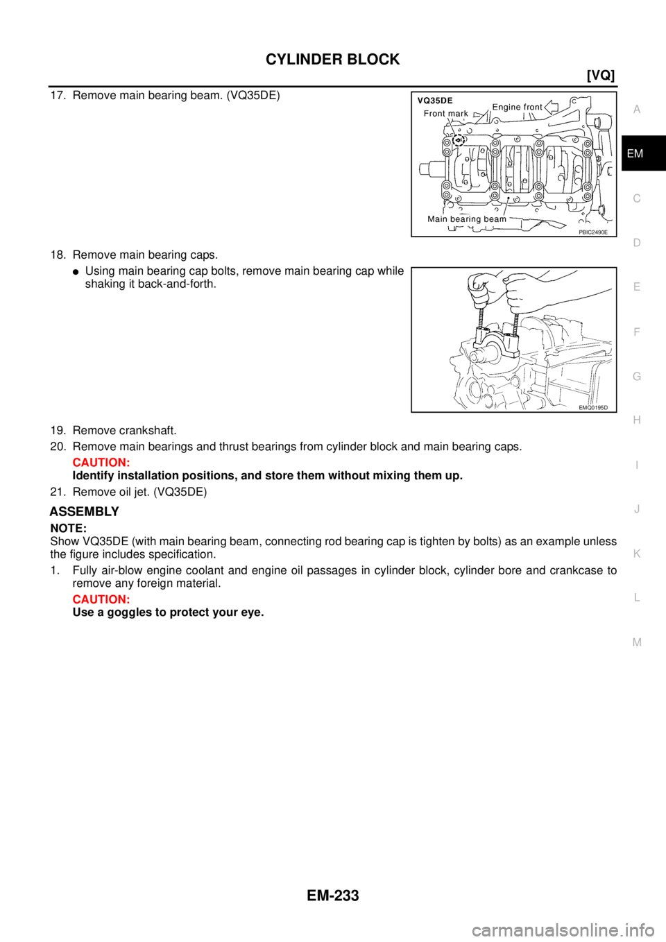
17. Remove main bearing beam. (VQ35DE)
18. Remove main bearing caps.
�Using main bearing cap bolts, remove main bearing cap while
shaking it back-and-forth.
19. Remove crankshaft.
20. Remove main bearings and thrust bearings from cylinder block and main bearing caps.
CAUTION:
Identify installation positions, and store them without mixing them up.
21. Remove oil jet. (VQ35DE)
ASSEMBLY
NOTE:
Show VQ35DE (with main bearing beam, connecting rod bearing cap is tighten by bolts) as an example unless
the figure includes specification.
1. Fully air-blow engine coolant and engine oil passages in cylinder block, cylinder bore and crankcase to
remove any foreign material.
CAUTION:
Use a goggles to protect your eye.
PBIC2490E
EMQ0195D
Page 2356 of 3502
![NISSAN TEANA 2003 Service Manual EM-248
[VQ]
CYLINDER BLOCK
Piston Pin Outer Diameter
Measure the outer diameter of piston pin with micrometer.
Connecting Rod Bushing Oil Clearance
(Connecting rod bushing oil clearance) = (Connecti](/manual-img/5/57392/w960_57392-2355.png "NISSAN TEANA 2003 Service Manual EM-248
[VQ]
CYLINDER BLOCK
Piston Pin Outer Diameter
Measure the outer diameter of piston pin with micrometer.
Connecting Rod Bushing Oil Clearance
(Connecting rod bushing oil clearance) = (Connecti")
EM-248
[VQ]
CYLINDER BLOCK
Piston Pin Outer Diameter
Measure the outer diameter of piston pin with micrometer.
Connecting Rod Bushing Oil Clearance
(Connecting rod bushing oil clearance) = (Connecting rod bushing inner diameter) – (Piston pin outer diame-
ter)
�If the calculated value exceeds the limit, replace connecting rod assembly and/or piston and piston pin
assembly.
�If replacing piston and piston pin assembly, refer to EM-240, "HOW TO SELECT PISTON" .
�If replacing connecting rod assembly, refer to EM-251, "CON-
NECTING ROD BEARING OIL CLEARANCE" to select the
connecting rod bearing.
Factory installed parts grading:
�Service parts apply only to grade “0”.
Unit: mm (in)
*: After installing in connecting rod
CYLINDER BLOCK DISTORTION
�Using scraper, remove gasket on the cylinder block surface, and also remove engine oil, scale, carbon, or
other contamination.
CAUTION:
Be careful not to allow gasket flakes to enter engine oil or engine coolant passages.Standard : 21.989 - 22.001 mm (0.8657 - 0.8662 in)
PBIC0117E
Standard : 0.005 - 0.017 mm (0.0002 - 0.0007 in)
Limit : 0.030 mm (0.0012 in)
PBIC0809E
Grade 0 1
Connecting rod bushing
inner diameter * 22.000 - 22 .0 06
(0.8661 - 0.8664) 22.006 - 22.012
(0.8664 - 0.8666)
Piston pin hole diameter 21.993 - 21.999
(0.8659 - 0.8661) 21.999 - 22. 005
(0.8661 - 0.8663)
Piston pin outer diameter 21.989 - 21.995
(0.8657- 0.8659) 21.995 - 22.001
(0.8659 - 0.8662)
PBIC0812E
Page 2430 of 3502
FSU-2
PRECAUTIONS
PRECAUTIONSPFP:00001
CautionBES0003G
�When installing rubber bushings, final tightening must be performed under unladen conditions with tires
on ground. Oil will shorten the life of rubber bushings. Be sure to wipe off any spilled oil.
–Unladen conditions mean that fuel, engine coolant and lubricant are full. A spare tire, a jack, hand tools
and mats are in designated positions.
�After servicing suspension parts, be sure to check wheel alignment.
�Self-lock nut are not reusable. Always use new ones when installing. Since new self-lock nuts are pre-
oiled, tighten as they are.
Page 2433 of 3502
 of each com")
FRONT SUSPENSION ASSEMBLY
FSU-5
C
D
F
G
H
I
J
K
L
MA
B
FSU
FRONT SUSPENSION ASSEMBLYPFP:54010
On-Vehicle Inspection BES0003K
Make sure that the mounting conditions (looseness, back lash) of each component and component status
(wear, damage) are normal.
INSPECTION OF TRANSVERSE LINK BALL JOINT END PLAY
1. Set front wheels in a straight-ahead position. Do not depress brake pedal.
2. Measure axial end play by placing an iron pry bar or a similar item between suspension arm and strut
assembly and prying up and down.
CAUTION:
Be careful not to damage ball joint boot. Do not damage the installation position by applying
excessive force.
STRUT INSPECTION
Check for oil leakage, damage, and breakage of installation positions.
Wheel Alignment InspectionBES0003L
DESCRIPTION
Measure wheel alignment under unladen conditions.
NOTE:
“Unladen” conditions mean that fuel, engine coolant, and lubricant are full. A spare tire, a jack, hand tools and
mats are in designated positions.
PRELIMINARY CHECK
1. Check Tires for improper air pressure and wear.
2. Check Road wheels for runout. Refer to WT-3, "
ROAD WHEEL" .
3. Check Wheel bearing axial end play. Refer to FAX-5, "
WHEEL BEARING INSPECTION" .
4. Check Transverse link ball joint axial end play. Refer to FSU-14, "
INSPECTION AFTER REMOVAL" .
5. Check Strut operation.
6. Check Each mounting point of axle and suspension for looseness and deformation.
7. Check Each link, rod, and member for cracks, deformation and other damage.
8. Check Vehicle height (posture).
INSPECTION OF CAMBER, CASTER AND KINGPIN INCLINATION ANGLES.
�Camber, caster, kingpin inclination angles cannot be adjusted.
�Before inspection, mount wheels onto turning radius gauge. Mount rear wheels onto a stand that has
same height so vehicle will remain horizontal.
Using a CCK Gauge
Install CCK gauge attachment [SST:KV991040S0] with the following procedure on wheel, then measure wheel
alignment.
1. Remove three wheel nuts, and install the guide bolts to hub
bolts.
2. Screw adapter into the plate until it contacts the plate tightly.
3. Screw center plate into the plate.
4. Insert plate on guide bolt. Put spring in, and then evenly screw
both guide bolt nuts. When fastening guide bolt nuts, do not
completely compress the spring.Axial end play : 0 mm (0 in)
SEIA0240E
Page 2446 of 3502

SERVICE DATA AND SPECIFICATIONS (SDS)PFP:00030
Wheel Alignment (Unladen*)BES0003T
*: Fuel, engine coolant and engine oil full. Spare tire, jack, hand t")
FSU-18
SERVICE DATA AND SPECIFICATIONS (SDS)
SERVICE DATA AND SPECIFICATIONS (SDS)PFP:00030
Wheel Alignment (Unladen*)BES0003T
*: Fuel, engine coolant and engine oil full. Spare tire, jack, hand tools and mats are in designated positions.
Ball JointBES0003U
Wheelarch Height (Unladen*)BES0003V
*: Fuel, engine coolant and engine oil full. Spare tire, jack, hand tools and mats are in designated positions.Camber
Degree minute (Decimal degree)Minimum –1° 00′ (–1.00°)
Nominal –0° 15′ (–0.25°)
Maximum 0° 30′ (0.50°)
Left and right difference 45′ (0.75°) or less
Caster
Degree minute (Decimal degree)Minimum 2° 05′ (2.08°)
Nominal 2° 50′ (2.83°)
Maximum 3° 35′ (3.58°)
Left and right difference 45′ (0.75°) or less
Kingpin inclination
Degree minute (Decimal degree)Minimum 13° 50′ (13.83°)
Nominal 14° 35′ (14.58°)
Maximum 15° 20′ (15.33°)
Total toe-inDistanceMinimum –0.3 mm (–0.01 in)
Nominal 0.7 mm (0.03 in)
Maximum 1.7 mm (0.07 in)
Angle (left plus right)
Degree minute (Degree)Minimum 0′ (0°)
Nominal 2′ (0.03°)
Maximum 4′ (0.07°)
Swing torque 0.5 - 3.4 N·m (0.06 - 0.34 kg-m, 5 - 30 in-lb)
Measurement on spring balance 13.5 - 91.9 N (1.4 - 9.3 kg, 3.08 - 20.5 lb)
Rotating torque 0.5 - 3.4 N·m (0.06 - 0.34 kg-m, 5 - 30 in-lb)
Axial end play0 mm (0 in)
Tire size 205/65R16 215/55R17
Front (Hf)721 mm
(28.39 in)718 mm
(28.27 in)
Rear (Hr)702 mm
(27.64 in)698 mm
(27.48 in)
SFA818A
Page 2491 of 3502

TERMINOLOGY
GI-45
C
D
E
F
G
H
I
J
K
L
MB
GI
TERMINOLOGYPFP:00011
SAE J1930 Terminology List BAS00081
All emission related terms used in this publication in accordance with SAE J1930 are listed. Accordingly, new
terms, new acronyms/abbreviations and old terms are listed in the following chart.
NEW TERMNEW ACRONYM /
ABBREVIATIONOLD TERM
Air cleaner ACL Air cleaner
Barometric pressure BARO ***
Barometric pressure sensor-BCDD BAROS-BCDD BCDD
Camshaft position CMP ***
Camshaft position sensor CMPS Crank angle sensor
Canister *** Canister
Carburetor CARB Carburetor
Charge air cooler CAC Intercooler
Closed loop CL Closed loop
Closed throttle position switch CTP switch Idle switch
Clutch pedal position switch CPP switch Clutch switch
Continuous fuel injection system CFI system ***
Continuous trap oxidizer system CTOX system ***
Crankshaft position CKP ***
Crankshaft position sensor CKPS ***
Data link connector DLC ***
Data link connector for CONSULT-II DLC for CONSULT-II Diagnostic connector for CONSULT-II
Diagnostic test mode DTM Diagnostic mode
Diagnostic test mode selector DTM selector Diagnostic mode selector
Diagnostic test mode I DTM I Mode I
Diagnostic test mode II DTM II Mode II
Diagnostic trouble code DTC Malfunction code
Direct fuel injection system DFI system ***
Distributor ignition system DI system Ignition timing control
Early fuel evaporation-mixture heater EFE-mixture heater Mixture heater
Early fuel evaporation system EFE system Mixture heater control
Electrically erasable programmable read
only memoryEEPROM ***
Electronic ignition system EI system Ignition timing control
Engine control EC ***
Engine control module ECM ECCS control unit
Engine coolant temperature ECT Engine temperature
Engine coolant temperature sensor ECTS Engine temperature sensor
Engine modification EM ***
Engine speed RPM Engine speed
Erasable programmable read only memory EPROM ***
Evaporative emission canister EVAP canister Canister
Evaporative emission system EVAP system Canister control solenoid valve
Exhaust gas recirculation valve EGR valve EGR valve
![NISSAN TEANA 2003 Service Manual ENGINE ASSEMBLY
EM-227
[VQ]
C
D
E
F
G
H
I
J
K
L
MA
EM
Summary of the inspection items:
* Transmission/transaxle/CVT fluid. power steering fluid, brake fluid, etc.Item Before starting engine Engine r](/manual-img/5/57392/w960_57392-2334.png "NISSAN TEANA 2003 Service Manual ENGINE ASSEMBLY
EM-227
[VQ]
C
D
E
F
G
H
I
J
K
L
MA
EM
Summary of the inspection items:
* Transmission/transaxle/CVT fluid. power steering fluid, brake fluid, etc.Item Before starting engine Engine r")