Page 824 of 3502

BR-6
BRAKE PEDAL
BRAKE PEDALPFP:46501
Inspection and AdjustmentBFS000BG
Play and clearance inspection between brake pedal and floor panel with pedal depressed.
�Check brake pedal height from dash lower panel (1).
�Adjust height referring to the following specifications.
ADJUSTMENT
1. Loosen stop lamp switch, brake switch and/or ASCD cancel
switch by turning it counterclockwise by 45°.
2. Loosen lock nut “A” on input rod, then rotate input rod to set,
brake pedal to the specified height, and tighten lock nut “A”.
Refer to BR-22, "
COMPONENTS" .
CAUTION:
Make sure the threaded end of input rod stays inside clevis.
3. With pedal pulled and held by hand, press stop lamp switch,
brake switch and/or ASCD cancel switch until its threaded end
contacts bracket.
4. With threaded end of stop lamp switch, brake switch and/or
ASCD cancel switch contacting bracket, rotate switch clockwise
by 45° to secure.
CAUTION:
�Make sure that the clearance “C” between bracket and
end of stop lamp switch, brake switch and/or ASCD can-
cel switch is within the standard.
�When locking stop lamp switch and ASCD cancel switch,
pull brake pedal to avoid moving toward the direction
where switches are being pressed.
5. Check the pedal play.
CAUTION:
Make sure that stop lamps goes off when pedal is released.
6. Start engine to check brake pedal depressed height.
H1Brake pedal free height (from dash lower panel
(1) top surface)195.8 - 205.8 mm
(7.71 - 8.10 in)
H
2
Depressed brake pedal height
[under a force of 490 N (50 kg, 110 lb) with
engine running]More than 115 mm
(4.53 in)
CClearance between the threaded end of stop
lamp switch, brake switch and/or ASCD cancel
switch (2) and bracket (3)0.74 - 1.96 mm
(0.0291 - 0.0772 in)
A Pedal play3-11 mm
(0.12 - 0.43 in)
SFIA2743J
PFIA0824E
Page 831 of 3502
BRAKE TUBE AND HOSE
BR-13
C
D
E
G
H
I
J
K
L
MA
B
BR
Inspection After InstallationBFS000BO
CAUTION:
If leakage occurs around brake tube and hose connections, retighten or, if damaged part is detected,
replace the damage part.
1. Check brake hoses, brake tubes, and connections for fluid leakage, damage, twists, deformation, contact
with other parts, and loose connections.
2. While depressing brake pedal under a force of 785 N (80 kg, 177 lb) with engine running for approximately
5 seconds, check for fluid leak each part.
Page 839 of 3502

BRAKE BOOSTER
BR-21
C
D
E
G
H
I
J
K
L
MA
B
BR
BRAKE BOOSTERPFP:47200
On-Board Inspection and ServiceBFS000BS
OPERATION CHECK
With engine stopped, change the vacuum to the atmospheric pres-
sure by depressing brake pedal several times. Then with brake
pedal fully depressed, start engine and when the vacuum pressure
reaches the standard, make sure that clearance between brake
pedal and floor panel decreases.
CAUTION:
Depressing pedal interval is approximately 5 seconds.
AIR TIGHT CHECK
�Run engine at idle for approximately 1 minute, and stop it after
applying vacuum to booster. Depress brake pedal normally to
change the vacuum to the atmospheric pressure. Make sure
distance between brake pedal and floor panel gradually
increases.
�Depress brake pedal while engine is running, and stop engine
with brake pedal is depressed. Brake pedal stroke should not
change after holding brake pedal down for 30 seconds.
CAUTION:
Depressing brake pedal interval is approximately at intervals 5
seconds.
BRA0037D
SBR365AA
Page 840 of 3502

BR-22
BRAKE BOOSTER
Removal and InstallationBFS000BT
COMPONENTS
CAUTION:
�Be careful not to splash brake fluid on painted areas; it may cause paint damage. If brake fluid is
splashed on painted surfaces of body, immediately wipe it off and them wash it away with water
immediately.
�Be careful not to deform or bend brake tube while removing and installing brake booster.
�Replace clevis pin if it is damaged.
�Be careful not to damage brake booster stud bolt threads. If brake booster is tilted or inclined dur-
ing installation, dash panel may damage the threads.
�Install check valve in the correct direction.
REMOVAL
1. Remove vacuum hose from brake booster. Refer to BR-24, "VACUUM LINES" .
2. Remove brake master cylinder. Refer to BR-14, "
Removal and Installation" .
3. Remove snap pin and clevis pin from brake pedal.
4. Remove nuts on brake booster and brake pedal assembly.
5. Remove brake booster from dash panel in engine room side.
1. Reservoir tank 2. Master cylinder 3. Brake booster
4. Gasket 5. Lock nut
SFIA2633E
SFIA2044E
Page 842 of 3502
BR-24
VACUUM LINES
VACUUM LINESPFP:41920
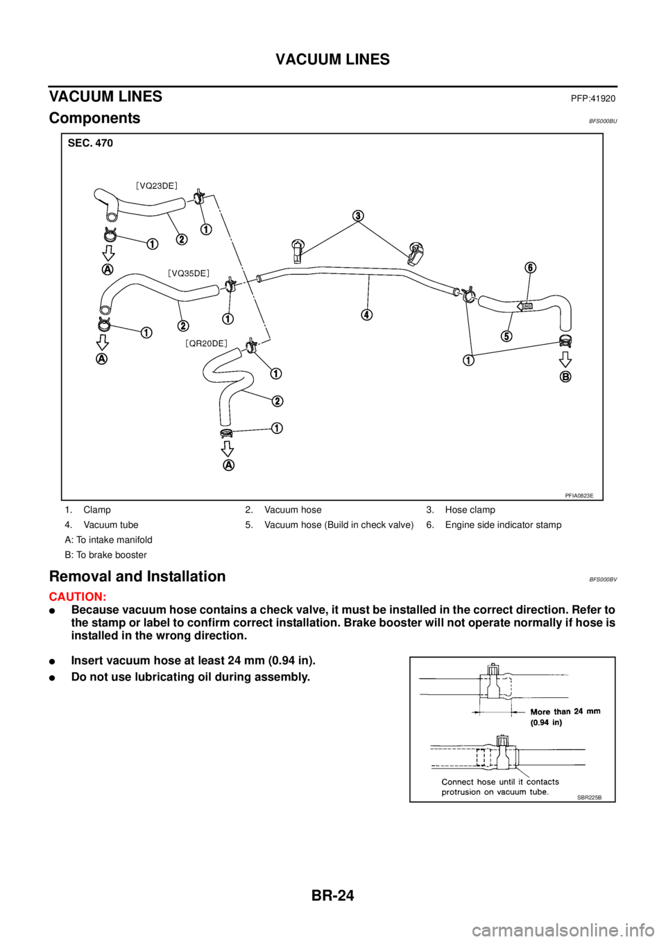
ComponentsBFS000BU
Removal and InstallationBFS000BV
CAUTION:
�Because vacuum hose contains a check valve, it must be installed in the correct direction. Refer to
the stamp or label to confirm correct installation. Brake booster will not operate normally if hose is
installed in the wrong direction.
�Insert vacuum hose at least 24 mm (0.94 in).
�Do not use lubricating oil during assembly.
1. Clamp 2. Vacuum hose 3. Hose clamp
4. Vacuum tube 5. Vacuum hose (Build in check valve) 6. Engine side indicator stamp
A: To intake manifold
B: To brake booster
PFIA0823E
SBR225B
Page 843 of 3502
VACUUM LINES
BR-25
C
D
E
G
H
I
J
K
L
MA
B
BR
InspectionBFS000BW
VISUAL INSPECTION
Check for improper assembly, damage and deterioration.
CHECK VALVE INSPECTION
Airtightness Inspection
Use a handy vacuum pump to check.
�Replace vacuum hose assembly if vacuum hose and check
valve are malfunctioning.When connected to booster side (1):
Vacuum decrease should decrease within 1.3 kPa
(10 mmHg, 0.39 inHg) for 15 seconds under a vac-
uum of −66.7 kPa (−500 mmHg, −19.69 inHg).
When connected to engine side (2):
No vacuum will be applied.
SFIA1306E
Page 858 of 3502

SERVICE DATA AND SPECIFICATIONS (SDS)PFP:00030
General SpecificationsBFS000C7
Unit: mm (in)
Brake PedalBFS000C8
Unit: mm (in)
Brake BoosterBFS000C9
Vacuum")
BR-40
SERVICE DATA AND SPECIFICATIONS (SDS)
SERVICE DATA AND SPECIFICATIONS (SDS)PFP:00030
General SpecificationsBFS000C7
Unit: mm (in)
Brake PedalBFS000C8
Unit: mm (in)
Brake BoosterBFS000C9
Vacuum type
Check ValveBFS000CA
Front Disc BrakeBFS000CB
Unit: mm (in) Front brakeCylinder bore diameter 57.2 (2.252)
Pad length × width × thickness 125.6 × 46.0 × 11.0 (4.94 × 1.81 × 0.433)
Rotor outer diameter × thickness 296 × 24 (11.65 × 0.945)
Rear brake Cylinder bore diameter 34.93 (1.375)
Pad length × width × thickness 83.0 × 33.0 × 8.5 (3.268 × 1.299 × 0.335)
Rotor outer diameter × thickness 292 × 9 (11.50 × 0.354)
Master cylinder Cylinder bore diameter 23.8 (0.94)
Control valve Valve model Electric brake force distribution
Brake booster Booster model M215T
Diaphragm diameterPrimary 228.5 (9.0)
Secondary 203 (8.0)
Recommended brake fluid DOT 3 or DOT 4
Brake pedal height (from dash lower panel top surface) 195.8 - 205.8 (7.71 - 8.10)
Depressed brake pedal height
[under a force of 490 N (50 kg, 110 lb) with engine running]More than 115 (4.53)
Clearance between threaded end of stop lamp switch, brake
switch and/or ASCD cancel switch and bracket 0.74 - 1.96 (0.0291 - 0.0772)
Pedal play3 - 11 (0.12 - 0.43)
Input rod installation standard dimension 125 mm (4.92 in)
Vacuum leakage
[at vacuum of –66.7 kPa (–500 mmHg, –19.69 inHg)]Within 1.3 kPa (10 mmHg, 0.39 inHg) of vacuum for 15 seconds
Brake padStandard thickness 11.0 (0.433)
Repair limit thickness 2.0 (0.079)
Disc rotorStandard thickness 24.0 (0.945)
Wear limit 22.0 (0.866)
Maximum uneven wear (measured at 8 positions) 0.010 (0.0004) or less
Runout limit (with it attached to vehicle) 0.040 (0.0016) or less
Page 863 of 3502
![NISSAN TEANA 2003 Service Manual PRECAUTIONS
BRC-3
[ABS]
C
D
E
G
H
I
J
K
L
MA
B
BRC
[ABS]PRECAUTIONSPFP:00001
Precautions for Supplemental Restraint System (SRS) “AIR BAG” and “SEAT
BELT PRE-TENSIONER”
BFS000CK
The Supplem](/manual-img/5/57392/w960_57392-862.png "NISSAN TEANA 2003 Service Manual PRECAUTIONS
BRC-3
[ABS]
C
D
E
G
H
I
J
K
L
MA
B
BRC
[ABS]PRECAUTIONSPFP:00001
Precautions for Supplemental Restraint System (SRS) “AIR BAG” and “SEAT
BELT PRE-TENSIONER”
BFS000CK
The Supplem")
PRECAUTIONS
BRC-3
[ABS]
C
D
E
G
H
I
J
K
L
MA
B
BRC
[ABS]PRECAUTIONSPFP:00001
Precautions for Supplemental Restraint System (SRS) “AIR BAG” and “SEAT
BELT PRE-TENSIONER”
BFS000CK
The Supplemental Restraint System such as “AIR BAG” and “SEAT BELT PRE-TENSIONER”, used along
with a front seat belt, helps to reduce the risk or severity of injury to the driver and front passenger for certain
types of collision. Information necessary to service the system safely is included in the SRS and SB section of
this Service Manual.
WARNING:
�To avoid rendering the SRS inoperative, which could increase the risk of personal injury or death
in the event of a collision which would result in air bag inflation, all maintenance must be per-
formed by an authorized NISSAN/INFINITI dealer.
�Improper maintenance, including incorrect removal and installation of the SRS, can lead to per-
sonal injury caused by unintentional activation of the system. For removal of Spiral Cable and Air
Bag Module, see the SRS section.
�Do not use electrical test equipment on any circuit related to the SRS unless instructed to in this
Service Manual. SRS wiring harnesses can be identified by yellow and/or orange harnesses or
harness connectors.
Precautions for Brake SystemBFS000CL
�Recommended fluid is brake fluid “DOT 3” or “DOT 4”. Refer to MA-14, "RECOMMENDED FLUIDS AND
LUBRICANTS" .
�Never reuse drained brake fluid.
�Be careful not to splash brake fluid on painted areas.
�To clean or wash all parts of master cylinder and disc brake caliper, use clean brake fluid.
�Never use mineral oils such as gasoline or kerosene. They will
ruin rubber parts of the hydraulic system.
�Using a flare nut wrench when removing flare nuts, and use a
flare nut torque wrench when tighten brake tube flare nuts.
�When installing brake tubes, be sure to check torque.
�Before working, turn ignition switch OFF and disconnect electri-
cal connector of ABS actuator and electric unit (control unit) or
battery negative terminal.
WARNING:
Clean brake pads and shoes with a waste cloth, then wipe with
a dust collector.
Precautions for Brake ControlBFS000CM
�During ABS operation, brake pedal lightly vibrates and a mechanical noise may be heard. This is normal.
�Just after starting vehicle after ignition switch ON, brake pedal may vibrate or motor operating noise may
be heard from engine room. This is a normal condition of operation check.
�Stopping distance may be longer than that of vehicles without ABS when vehicle drives on rough, gravel,
or snow-covered (fresh, deep snow) roads.
�When an error is indicated by ABS or another warning lamp, collect all necessary information from cus-
tomer (what symptoms are present under what conditions) and check for simple causes before starting
diagnostic servicing. Besides electrical system inspection, check brake booster operation, brake fluid
level, and fluid leaks.
�If tire size and type are used in an improper combination, or brake pads are not Genuine NISSAN parts,
stopping distance or steering stability may deteriorate.
�If there is a radio, antenna, or antenna lead-in wire (including wiring) near control module, ABS function
may have a malfunction or error.
�If aftermarket parts (car stereo, CD player, etc.) have been installed, check for incidents such as harness
pinches, open circuits, and improper wiring.
SBR820BA