Page 822 of 3502
BR-4
PREPARATION
PREPARATIONPFP:00002
Special Service ToolsBFS000BD
Commercial Service ToolsBFS000BE
Tool number
Tool nameDescription
GG94310000
Flare nut torque wrench
a:10 mm (0.39 in) / 12 mm (0.47 in)Installing each brake tube
NT406
Tool nameDescription
Pin punch
Tip diameter: 4 mm (0.16 in) dia.Removing and installing reservoir tank
pin
ZZA0515D
Page 828 of 3502

BR-10
BRAKE FLUID
Bleeding Brake SystemBFS000BK
CAUTION:
�Carefully monitor brake fluid level in reservoir tank during
bleeding operation.
�Refill with new brake fluid “DOT 3 or DOT 4”. Make sure it is
at least half way at all times while bleeding air out of sys-
tem.
�Place a container under master cylinder not to spill brake
fluid.
�Turn ignition switch to the OFF and disconnect connector
for ABS actuator and electric unit (control unit) or battery
cable from negative terminal before working.
1. Connect a vinyl tube to rear right brake caliper bleed valve.
2. Fully depress brake pedal 4 or 5 times.
3. With brake pedal depressed, loosen bleed valve to bleed air in
brake line, and then tighten it immediately.
4. Repeat steps 2 and 3 until all of the air is out of the brake line.
5. Tighten bleed valve to the specified torque. Refer to front disc
brake: BR-26, "
Components" , rear disc brake: BR-33, "Compo-
nents" .
6. From step 1 to 5 above, with master cylinder reservoir tank filled
at least half way, bleed air from brake hydraulic line bleed valves
in the following order:
Rear right brake→Front left brake→Rear left brake→Front right brake
PFIA0403J
BRA0007D
Page 830 of 3502

BR-12
BRAKE TUBE AND HOSE
Removal and Installation of Front Brake Tube and HoseBFS000BM
REMOVAL
1. Drain brake fluid. Refer to BR-9, "Drain and Refill" .
2. Using a flare nut wrench, remove brake tube from brake hose.
3. Remove union bolt and remove brake hose from brake caliper
assembly.
4. Remove lock plate and remove brake hose from vehicle.
INSTALLATION
1. Install brake hose by aligning with the protrusion on brake caliper assembly, and tighten union bolt to the
specified torque. Refer to BR-11, "
Hydraulic Circuit" .
CAUTION:
Do not reuse copper washer.
2. Install brake hose to brake tube. Temporarily tighten flare nut by hand as much as possible. Secure them
to bracket with lock plate.
3. Using a flare nut torque wrench, tighten flare nut to the specified torque. Refer to BR-11, "
Hydraulic Cir-
cuit" .
4. Refill with new brake fluid and bleed air. Refer to BR-10, "
Bleeding Brake System" .
Removal and Installation of Rear Brake Tube and HoseBFS000BN
REMOVAL
1. Drain brake fluid. Refer to BR-9, "Drain and Refill" .
2. Using a flare nut wrench, remove brake tube from brake hose.
3. Remove union bolt and remove brake hose from brake caliper
assembly.
4. Remove lock plate and remove brake hose from vehicle.
INSTALLATION
1. Install the L-shape metal fitting of brake hose to brake caliper
assembly positioning hole, and then tighten union bolt to the
specified torque. Refer to BR-11, "
Hydraulic Circuit" .
CAUTION:
Do not reuse copper washer.
2. Install brake hose to brake tube. Temporarily tighten flare nut by
hand as much as possible. Secure them to bracket with lock
plate.
3. Using a flare nut torque wrench, tighten flare nut to the specified
torque. Refer to BR-11, "
Hydraulic Circuit" .
4. Refill with new brake fluid and bleed air. Refer to BR-10, "
Bleed-
ing Brake System" .
SFIA2057E
SFIA2048E
SFIA2049E
Page 832 of 3502

BR-14
BRAKE MASTER CYLINDER
BRAKE MASTER CYLINDERPFP:46010
On-Board InspectionBFS000BP
LEAK INSPECTION
�Check for leaking in a master cylinder installation surface, a reservoir tank installation surface, and brake
tube connections.
Removal and InstallationBFS000BQ
CAUTION:
Be careful not to splash brake fluid on painted areas; it way cause paint damage. If brake fluid is
splashed on painted surfaces of body, immediately wipe it off and them wash it away with water imme-
diately.
REMOVAL
1. Drain brake fluid. Refer to BR-9, "Drain and Refill" .
2. Remove brake fluid level switch harness connector.
3. Using a flare nut wrench, remove brake tubes from master cylinder assembly.
4. Remove master cylinder mounting nuts, remove master cylinder assembly from vehicle.
INSTALLATION
CAUTION:
�Refill with new brake fluid “DOT 3 or DOT 4”.
�Do not reuse drained brake fluid.
1. Install in the reverse order of removal and tighten nuts to the specified torque. Refer to BR-22, "
COMPO-
NENTS" .
Models with VDC
�Apply silicon grease in inner kit to O-ring and it's surrounding
areas and to booster side inner wall.
CAUTION:
�Do not damage the sliding surface of primary piston rod
and do not allow foreign materials on it's surface.
�Do not reuse the O-ring.
2. Install brake tube to master cylinder assembly and temporarily
tighten flare nut by hand.
3. Tighten brake tube flare nut to the specified torque using a flare
nut torque wrench. Refer to BR-11, "
Hydraulic Circuit" .
4. Install brake fluid level switch harness connector.
5. Refill with new brake fluid and bleed air. Refer to BR-10, "
Bleeding Brake System" .
SFIA1302E
Page 841 of 3502
 to brake")
BRAKE BOOSTER
BR-23
C
D
E
G
H
I
J
K
L
MA
B
BR
INSPECTION AFTER REMOVAL
Output Rod Length Inspection
1. Using a handy vacuum pump, apply a vacuum of −66.7 kPa (−
500 mmHg, −19.69 inHg) to brake booster.
2. Check output rod length.
INSTALLATION
1. Loosen lock nut to adjust input rod length so that the length “B”
(shown in the figure) satisfies the specified value.
2. Temporarily tighten lock nut after adjusting the length “B” to the
specified value, and then install brake booster on dash panel.
CAUTION:
Always install gasket between brake booster and dash-
board panel.
3. Install brake booster and brake pedal assembly nuts and bolt,
and then tighten to the specified torque. Refer to BR-7,
"Removal and Installation" .
4. Connect brake pedal with clevis of input rod.
5. Install brake master cylinder. Refer to BR-14, "
Removal and Installation" .
6. Install vacuum hose. Refer to BR-24, "
VACUUM LINES" .
7. Adjust brake pedal free height and the play of brake pedal. Refer to BR-6, "
Inspection and Adjustment" .
8. Tighten input rod lock nut to the specified torque. Refer to BR-22, "
COMPONENTS" .
9. Refill with new brake fluid and bleed air. Refer to BR-11, "
Hydraulic Circuit" . Standard dimension when applying vacuum of −66.7
kPa (−500 mmHg, −19.69 inHg) (Reference value)
Models without VDC : 10.4 mm (0.409 in)
Models with VDC : −6.2 mm (−0.244 in)
SBR208E
Length “B” : 125 mm (4.92 in)
SGIA0060E
Page 844 of 3502

BR-26
FRONT DISC BRAKE
FRONT DISC BRAKEPFP:41000
On-Board InspectionBFS000BX
PAD WEAR INSPECTION
�Check pad thickness from the inspection hole on cylinder body.
Check use a scale for inspection necessary.
ComponentsBFS000BY
WARNING:
Clean dust on caliper and brake pads with a vacuum dust collector to minimize the hazard of airborne
particles or other materials.
CAUTION:
�While removing cylinder body, never depress brake pedal because piston will pop out. Standard thickness : 11.0 mm (0.433 in)
Repair limit thickness : 2.0 mm (0.079 in)
BRA0010D
1. Union bolt 2. Brake hose 3. Copper washer
4. Cap 5. Bleed valve 6. Sliding pin bolt
7. Cylinder body 8. Piston seal 9. Piston
10. Piston boot 11. Inner shim cover 12. Inner shim
13. Pad wear sensor
(Only for inner pad RH)14. Inner pad 15. Pad retainer
16. Outer pad 17. Outer shim 18. Sliding pin
19. Sliding pin boot 20. Bushing 21. Torque member
22. Torque member mounting bolt
Refer to GI-10, "
Components" and the followings for the symbols in the figure.
1: Apply rubber grease.
2: Apply PBC (Poly Butyl Cuprysil) grease or silicone-based grease.
3: Apply polyglycol ether based lubricant.
: Apply brake fluid.
PFIA0837E
Page 845 of 3502

FRONT DISC BRAKE
BR-27
C
D
E
G
H
I
J
K
L
MA
B
BR
�It is not necessary to remove bolts on torque member and brake hose except for disassembly or
replacement of caliper assembly. In this case, suspend cylinder body with wire so as not to stretch
brake hose.
�Do not damage piston boot.
�If any shim is subject to serious corrosion, replace it with a new one.
�Always replace shim and inner shim cover as a set when replacing brake pads.
�Keep rotor clean from brake fluid.
�Burnish brake contact surface after refinishing or replacing rotors, after replacing pads, or it a soft
pedal occurs at very low mileage. Refer toBR-32, "
BRAKE BURNISHING PROCEDURE" .
Removal and Installation of Brake PadBFS000BZ
REMOVAL
1. Remove tyres from vehicle.
2. Remove lower sliding pin bolt.
3. Suspend cylinder body with wire, and remove pads, pad retain-
ers, shims, and shim cover from torque member.
CAUTION:
When removing pad retainers from torque member, lift pad
retainers in the direction by the arrow (shown in the figure)
so as not to damage it.
INSTALLATION
1. Apply PBC (Poly Butyl Cuprysil) grease or silicone-based
grease to the both sides of inner shim and outer shim, install
inner shim and inner shim cover to inner pad and outer shim to
outer pad.
CAUTION:
Securely install shim cover according to shim mounting
direction.
2. Install pad retainers and pads to torque member.
CAUTION:
Securely assemble pad retainers so that they are not being
lifted up from torque member.
3. Press in piston until pads can be installed, and then install cylin-
der body to torque member.
NOTE:
Using a disc brake piston tool (commercial service tool) to easily
press piston in.
CAUTION:
When replacing pads with new ones, press in piston until
pads can be installed. In this case, carefully monitor brake fluid level in reservoir tank because
brake fluid will return to master cylinder reservoir tank.
4. Install lower sliding pin bolt, and tighten it to the specified torque. Refer to BR-26, "
Components" .
5. Secure disc rotor with wheel nut. Depress brake pedal a few times until it gets a responsive touch.
6. Check front disc brake for drag.
7. Install tyres to vehicle.
SBR556E
PFIA0267E
PFIA0273E
Page 846 of 3502
BR-28
FRONT DISC BRAKE
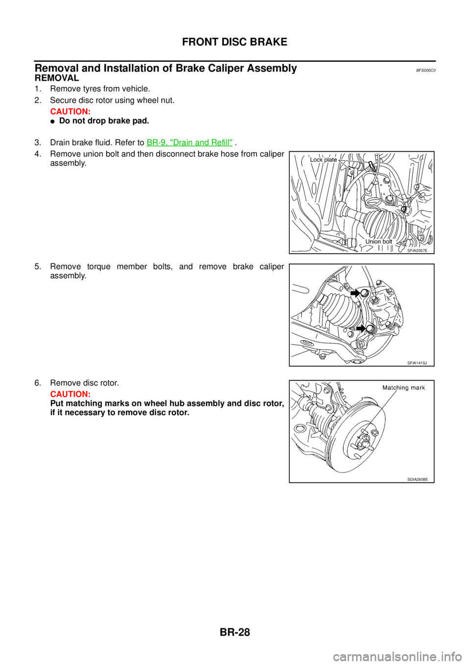
Removal and Installation of Brake Caliper AssemblyBFS000C0
REMOVAL
1. Remove tyres from vehicle.
2. Secure disc rotor using wheel nut.
CAUTION:
�Do not drop brake pad.
3. Drain brake fluid. Refer to BR-9, "
Drain and Refill" .
4. Remove union bolt and then disconnect brake hose from caliper
assembly.
5. Remove torque member bolts, and remove brake caliper
assembly.
6. Remove disc rotor.
CAUTION:
Put matching marks on wheel hub assembly and disc rotor,
if it necessary to remove disc rotor.
SFIA2057E
SFIA1410J
SDIA2608E
 / 12 mm (0")