Page 2063 of 3189
TROUBLE DIAGNOSIS
ATC-83
C
D
E
F
G
H
I
K
L
MA
B
AT C
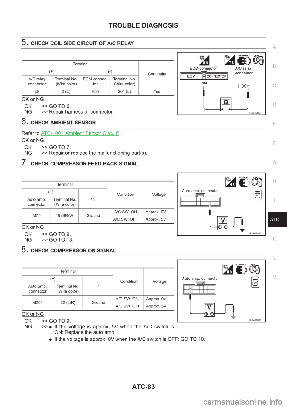
5.CHECK COIL SIDE CIRCUIT OF A/C RELAY
OK or NG
OK >> GO TO 6.
NG >> Repair harness or connector.
6.CHECK AMBIENT SENSOR
Refer to ATC-100, "
Ambient Sensor Circuit" .
OK or NG
OK >> GO TO 7.
NG >> Repair or replace the malfunctioning part(s).
7.CHECK COMPRESSOR FEED BACK SIGNAL
OK or NG
OK >> GO TO 9.
NG >> GO TO 13.
8.CHECK COMPRESSOR ON SIGNAL
OK or NG
OK >> GO TO 9.
NG >>
●If the voltage is approx. 5V when the A/C switch is
ON: Replace the auto amp.
●If the voltage is approx. 0V when the A/C switch is OFF: GO TO 10.
Terminal
Continuity (+) (-)
A/C relay
connectorTerminal No.
(Wire color)ECM connec-
torTerminal No.
(Wire color)
E9 2 (L) F58 204 (L) Yes
RJIA1705E
Terminal
Condition Voltage (+)
(-)
Auto amp.
connectorTe r m i n a l N o .
(Wire color)
M75 18 (BR/W) GroundA/C SW: ON Approx. 0V
A/C SW: OFF Approx. 5V
RJIA0796E
Terminal
Condition Voltage (+)
(-)
Auto amp.
connectorTerminal No.
(Wire color)
M205 22 (L/R) GroundA/C SW: ON Approx. 0V
A/C SW: OFF Approx. 5V
RJIA0798E
Page 2064 of 3189
ATC-84
TROUBLE DIAGNOSIS
9. CHECK MULTIPLEX COMMUNICATION CIRCUIT
Refer to ATC-109, "
Multiplex Communication Circuit" .
OK or NG
OK >> INSPECTION END
NG >> Repair harness or connector.
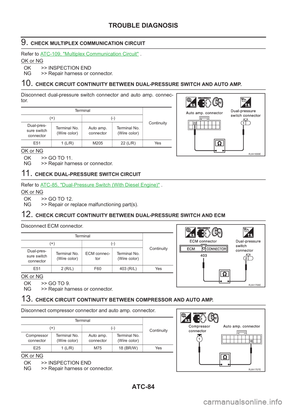
10. CHECK CIRCUIT CONTINUITY BETWEEN DUAL-PRESSURE SWITCH AND AUTO AMP.
Disconnect dual-pressure switch connector and auto amp. connec-
tor.
OK or NG
OK >> GO TO 11.
NG >> Repair harness or connector.
11 . CHECK DUAL-PRESSURE SWITCH CIRCUIT
Refer to AT C - 8 5 , "
Dual-Pressure Switch (With Diesel Engine)" .
OK or NG
OK >> GO TO 12.
NG >> Repair or replace malfunctioning part(s).
12. CHECK CIRCUIT CONTINUITY BETWEEN DUAL-PRESSURE SWITCH AND ECM
Disconnect ECM connector.
OK or NG
OK >> GO TO 9.
NG >> Repair harness or connector.
13. CHECK CIRCUIT CONTINUITY BETWEEN COMPRESSOR AND AUTO AMP.
Disconnect compressor connector and auto amp. connector.
OK or NG
OK >> INSPECTION END
NG >> Repair harness or connector.
Terminal
Continuity (+) (-)
Dual-pres-
sure switch
connectorTe r m i n a l N o .
(Wire color)Auto amp.
connectorTerminal No.
(Wire color)
E51 1 (L/R) M205 22 (L/R) Yes
RJIA1699E
Terminal
Continuity (+) (-)
Dual-pres-
sure switch
connectorTe r m i n a l N o .
(Wire color)ECM connec-
torTerminal No.
(Wire color)
E51 2 (R/L) F60 403 (R/L) Yes
RJIA1706E
Terminal
Continuity (+) (-)
Compressor
connectorTe r m i n a l N o .
(Wire color)Auto amp.
connectorTerminal No.
(Wire color)
E25 1 (L/R) M75 18 (BR/W) Yes
RJIA1707E
Page 2099 of 3189
BLOWER UNIT
ATC-119
C
D
E
F
G
H
I
K
L
MA
B
AT C
BLOWER UNITPFP:27200
Removal and InstallationEJS00206
REMOVAL
1. Remove the glove box assembly.
2. Remove the glove box cover and instrument lower assist panel.
3. Remove the ECM with ECM bracket.
4. Remove the blower unit fixing bolt and screw.
5. Disconnect the blower motor connector, intake door motor con-
nector and auto amp. connector.
6. Remove the harness fixing clip.
7. Move the blower unit downwards.
CAUTION:
Slide the blower unit toward the passenger side, remove loca-
tion pins (2 pieces), then move it downwards.
8. Remove the blower unit.
INSTALLATION
CAUTION:
●Make sure the location pins (2 pieces) are securely installed.
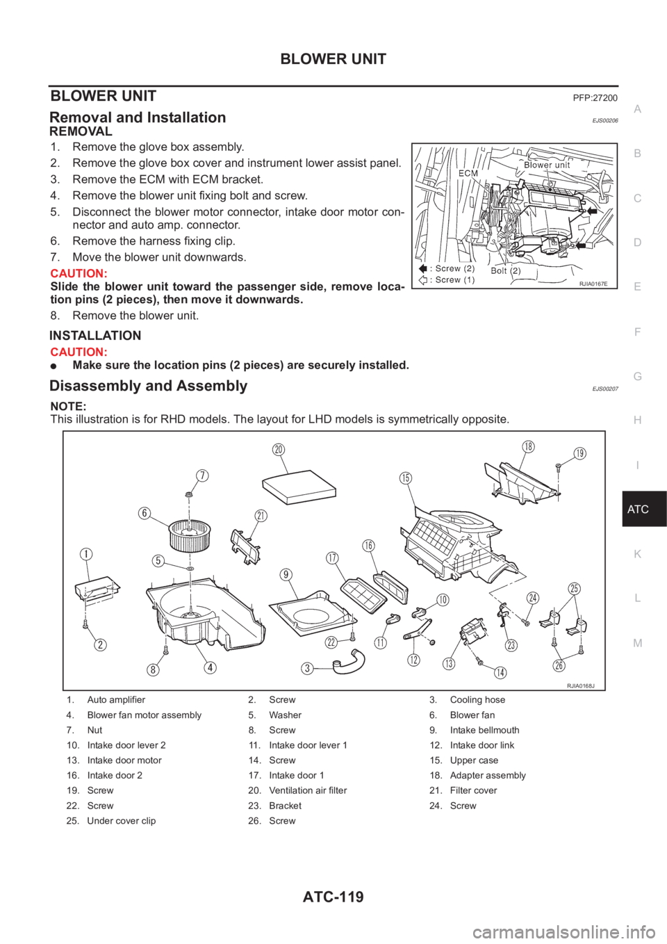
Disassembly and AssemblyEJS00207
NOTE:
This illustration is for RHD models. The layout for LHD models is symmetrically opposite.
RJIA0167E
1. Auto amplifier 2. Screw 3. Cooling hose
4. Blower fan motor assembly 5. Washer 6. Blower fan
7. Nut 8. Screw 9. Intake bellmouth
10. Intake door lever 2 11. Intake door lever 1 12. Intake door link
13. Intake door motor 14. Screw 15. Upper case
16. Intake door 2 17. Intake door 1 18. Adapter assembly
19. Screw 20. Ventilation air filter 21. Filter cover
22. Screw 23. Bracket 24. Screw
25. Under cover clip 26. Screw
RJIA0168J
Page 2447 of 3189
WATER TEMPERATURE GAUGE (QG AND YD ENGINE MODELS WITH COMMON RAIL)NJEL0442S09The water temperature gauge indicates the engine coolant temperature.
ECM provides a engine coolant temperature signal to combination meter forwater temperature gauge with
CAN communication line.
WATER TEMPERATURE GAUGE (YD ENGINE MODELS WITHOUT COMMON RAIL)NJEL0442S04The water temperature gauge indicates the engine coolant temperature. The reading on the gauge is based
on the resistance of the thermal transmitter.
As the temperature of the coolant increases, the resistance of the thermaltransmitter decreases. A variable
ground is supplied to terminal 35 of the combination meter for the water temperature gauge. The needle on
the gauge moves from “C” to “H”.
TACHOMETER (QG AND YD ENGINE MODELS WITH COMMON RAIL)NJEL0442S10The tachometer indicates engine speed in revolution per minutes (rpm). ECM provides an engine speed sig-
nal to combination meter for tachometer with CAN communication line.
TACHOMETER (YD ENGINE MODELS WITHOUT COMMON RAIL)NJEL0442S05The tachometer indicates engine speed in revolutions per minute (rpm).
The tachometer is regulated by a signal
from terminal 32 (Gasoline engine models) or 439 (Diesel engine models) ofthe ECM
to combination meter terminal 53 for the tachometer.
FUEL GAUGENJEL0442S06The fuel gauge indicates the approximate fuel level in the fuel tank.
The fuel gauge is regulated by a variable ground signal supplied
from body grounds F118 (QG engine models), M28 and M67
through terminals 33 and 32 of combination meter,
through terminal 1 of the fuel level sensor unit and
through terminal 4 of the fuel level sensor unit
to combination meter terminal 34 for the fuel gauge.
SPEEDOMETER (MODELS WITH ABS)NJEL0442S11The combination meter receives a signal from the ABS actuator and electricunit. The speedometer converts
the signal into the vehicle speed displayed.
SPEEDOMETER (MODELS WITHOUT ABS)NJEL0442S07The combination meter provides a voltage signal to the vehicle speed sensor for the speedometer.
The voltage is supplied
from combination meter terminal 13 for the speedometer
to terminal 1 of the vehicle speed sensor.
Ground is supplied
from body grounds F118 (QG engine models), M28 and M67
through terminals 32 and 14 of combination meter
to teminal 2 of the vehicle speed sensor.
The speedometer converts the voltage into the vehicle speed displayed.
GI
MA
EM
LC
EC
FE
CL
MT
AT
AX
SU
BR
ST
RS
BT
HA
SC
IDX
METERS AND GAUGES
System Description (Cont’d)
EL-111
Page 2460 of 3189
Models with ABS=NJEL0448S0402
1 ABS ACTUATOR AND ELECTRIC UNIT SYSTEM INSPECTION
Perform ABS actuator and electric unit self-diagnosis.
Refer to BR-55, “CONSULT-II Functions”.
OK or NG
OK GO TO 2.
NG Check ABS control system. Refer to BR-62, “TROUBLE DIAGNOSIS — BASIC INSPEC-
TION”.
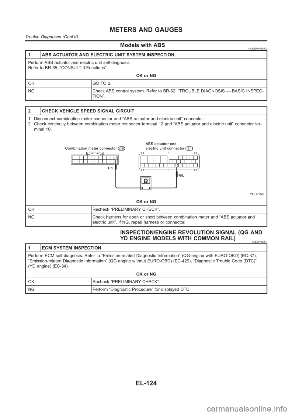
2 CHECK VEHICLE SPEED SIGNAL CIRCUIT
1. Disconnect combination meter connector and “ABS actuator and electricunit” connector.
2. Check continuity between combination meter connector terminal 12 and “ABS actuator and electric unit” connector ter-
minal 10.
YEL815D
OK or NG
OK Recheck “PRELIMINARY CHECK”.
NG Check harness for open or short between combination meter and “ABS actuator and
electric unit”. If NG, repair harness or connector.
INSPECTION/ENGINE REVOLUTION SIGNAL (QG AND
YD ENGINE MODELS WITH COMMON RAIL)
NJEL0448S11
1 ECM SYSTEM INSPECTION
Perform ECM self-diagnosis. Refer to “Emission-related Diagnostic Information” (QG engine with EURO-OBD) (EC-37),
“Emission-related Diagnostic Information” (QG engine without EURO-OBD) (EC-429), “Diagnostic Trouble Code (DTC)”
(YD engine) (EC-34).
OK or NG
OK Recheck “PRELIMINARY CHECK”.
NG Perform “Diagnostic Procedure” for displayed DTC.
METERS AND GAUGES
Trouble Diagnoses (Cont’d)
EL-124
Page 2461 of 3189
INSPECTION/ENGINE REVOLUTION SIGNAL (YD
ENGINE MODELS WITHOUT COMMON RAIL)
=NJEL0448S05
1 CHECK ECM OUTPUT
1. Start engine.
2. Check voltage between combination meter terminals 53 and ground at idleand 2,000 rpm.
YEL816D
OK or NG
OK Engine revolution signal is OK.
NG Harness for open or short between ECM and combination meter
GI
MA
EM
LC
EC
FE
CL
MT
AT
AX
SU
BR
ST
RS
BT
HA
SC
IDX
METERS AND GAUGES
Trouble Diagnoses (Cont’d)
EL-125
Page 2463 of 3189
INSPECTION/THERMAL TRANSMITTER (YD ENGINE
MODELS WITHOUT COMMON RAIL)
=NJEL0448S07
1 CHECK THERMAL TRANSMITTER
Refer to “THERMAL TRANSMITTER CHECK” (EL-128).
OK or NG
OK GO TO 2.
NG Replace.
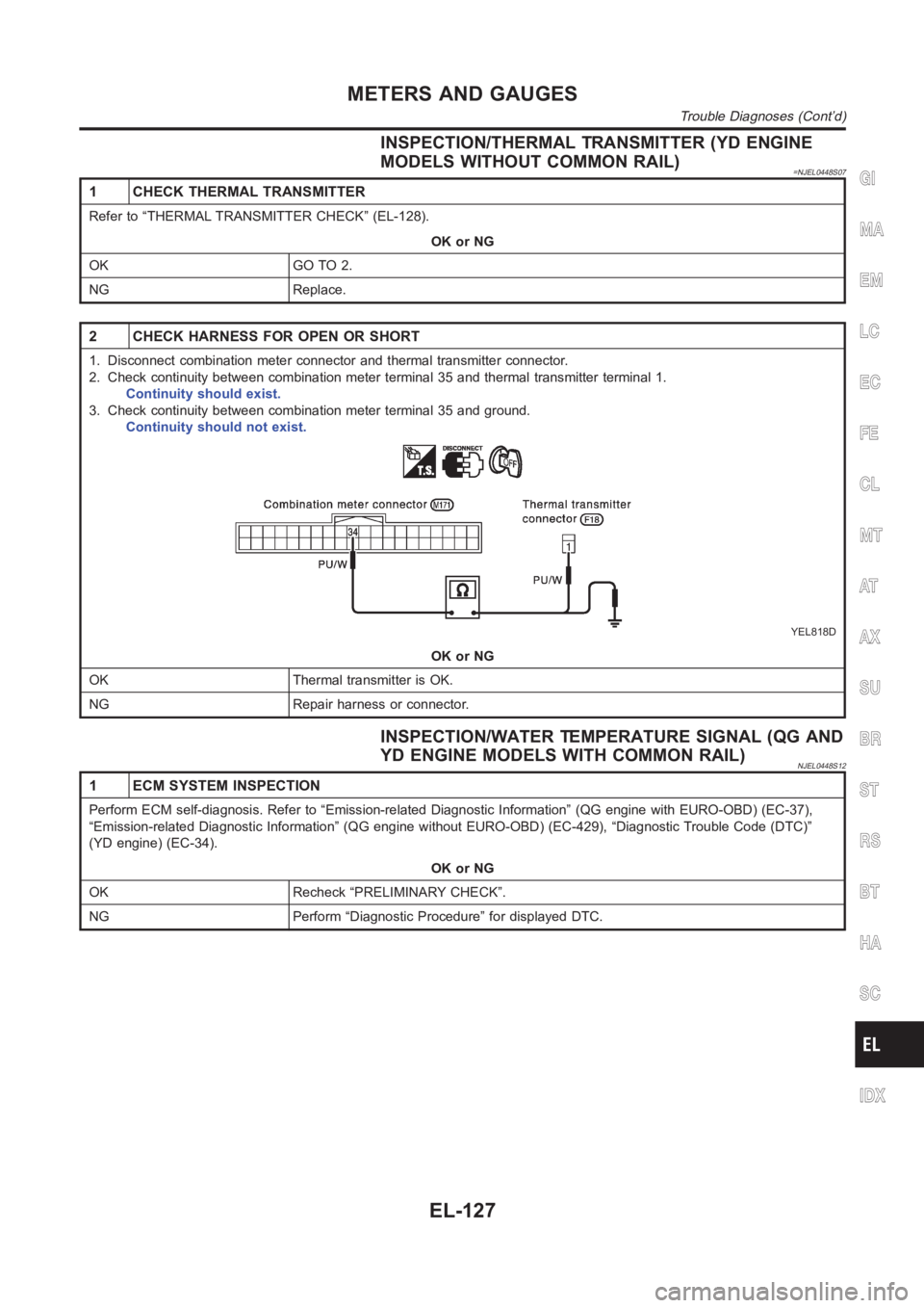
2 CHECK HARNESS FOR OPEN OR SHORT
1. Disconnect combination meter connector and thermal transmitter connector.
2. Check continuity between combination meter terminal 35 and thermal transmitter terminal 1.
Continuity should exist.
3. Check continuity between combination meter terminal 35 and ground.
Continuity should not exist.
YEL818D
OK or NG
OK Thermal transmitter is OK.
NG Repair harness or connector.
INSPECTION/WATER TEMPERATURE SIGNAL (QG AND
YD ENGINE MODELS WITH COMMON RAIL)
NJEL0448S12
1 ECM SYSTEM INSPECTION
Perform ECM self-diagnosis. Refer to “Emission-related Diagnostic Information” (QG engine with EURO-OBD) (EC-37),
“Emission-related Diagnostic Information” (QG engine without EURO-OBD) (EC-429), “Diagnostic Trouble Code (DTC)”
(YD engine) (EC-34).
OK or NG
OK Recheck “PRELIMINARY CHECK”.
NG Perform “Diagnostic Procedure” for displayed DTC.
GI
MA
EM
LC
EC
FE
CL
MT
AT
AX
SU
BR
ST
RS
BT
HA
SC
IDX
METERS AND GAUGES
Trouble Diagnoses (Cont’d)
EL-127
Page 2471 of 3189
NEL796
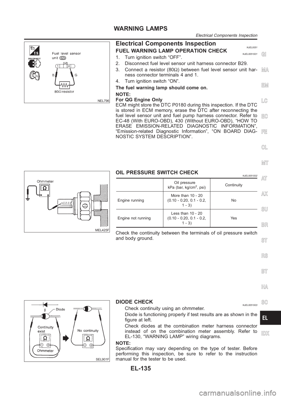
Electrical Components InspectionNJEL0051FUEL WARNING LAMP OPERATION CHECKNJEL0051S011. Turn ignition switch “OFF”.
2. Disconnect fuel level sensor unit harness connector B29.
3. Connect a resistor (80Ω) between fuel level sensor unit har-
ness connector terminals 4 and 1.
4. Turn ignition switch “ON”.
The fuel warning lamp should come on.
NOTE:
For QG Engine Only
ECM might store the DTC P0180 during this inspection. If the DTC
is stored in ECM memory, erase the DTC after reconnecting the
fuel level sensor unit and fuel pump harness connector. Refer to
EC-48 (With EURO-OBD), 430 (Without EURO-OBD), “HOW TO
ERASE EMISSION-RELATED DIAGNOSTIC INFORMATION”,
“Emission-related Diagnostic Information”, “ON BOARD DIAG-
NOSTIC SYSTEM DESCRIPTION”.
MEL425F
OIL PRESSURE SWITCH CHECKNJEL0051S02
Oil pressure
kPa (bar, kg/cm2, psi)Continuity
Engine runningMore than 10 - 20
(0.10 - 0.20, 0.1 - 0.2,
1-3)No
Engine not runningLess than 10 - 20
(0.10 - 0.20, 0.1 - 0.2,
1-3)Ye s
Check the continuity between the terminals of oil pressure switch
and body ground.
SEL901F
DIODE CHECKNJEL0051S03Check continuity using an ohmmeter.
Diode is functioning properly if test results are as shown in the
figure at left.
Check diodes at the combination meter harness connector
instead of on the combination meter assembly. Refer to
EL-130, “WARNING LAMP” wiring diagrams.
NOTE:
Specification may vary depending on the type of tester. Before
performing this inspection, be sure to refer to the instruction
manual for the tester to be used.
GI
MA
EM
LC
EC
FE
CL
MT
AT
AX
SU
BR
ST
RS
BT
HA
SC
IDX
WARNING LAMPS
Electrical Components Inspection
EL-135