Page 1225 of 3189
2) Start engine and run it for at least 2 seconds at idle speed.
(If engine does not run, turn ignition switch to “START” for at
least 2 seconds.)
3) Turn ignition switch “OFF”, wait at least 5 seconds and then
turn “ON”.
4) Perform “Diagnostic Test Mode II (Self-diagnostic results)” with
ECM.
5) If DTC is detected, go to “Diagnostic Procedure”, EC-173.
GI
MA
EM
LC
FE
CL
MT
AT
AX
SU
BR
ST
RS
BT
HA
SC
EL
IDX
DTC P1600 P3·PUMP COMM LINEYD
DTC Confirmation Procedure (Cont’d)
EC-171
Page 1227 of 3189

Diagnostic ProcedureNJEC0713
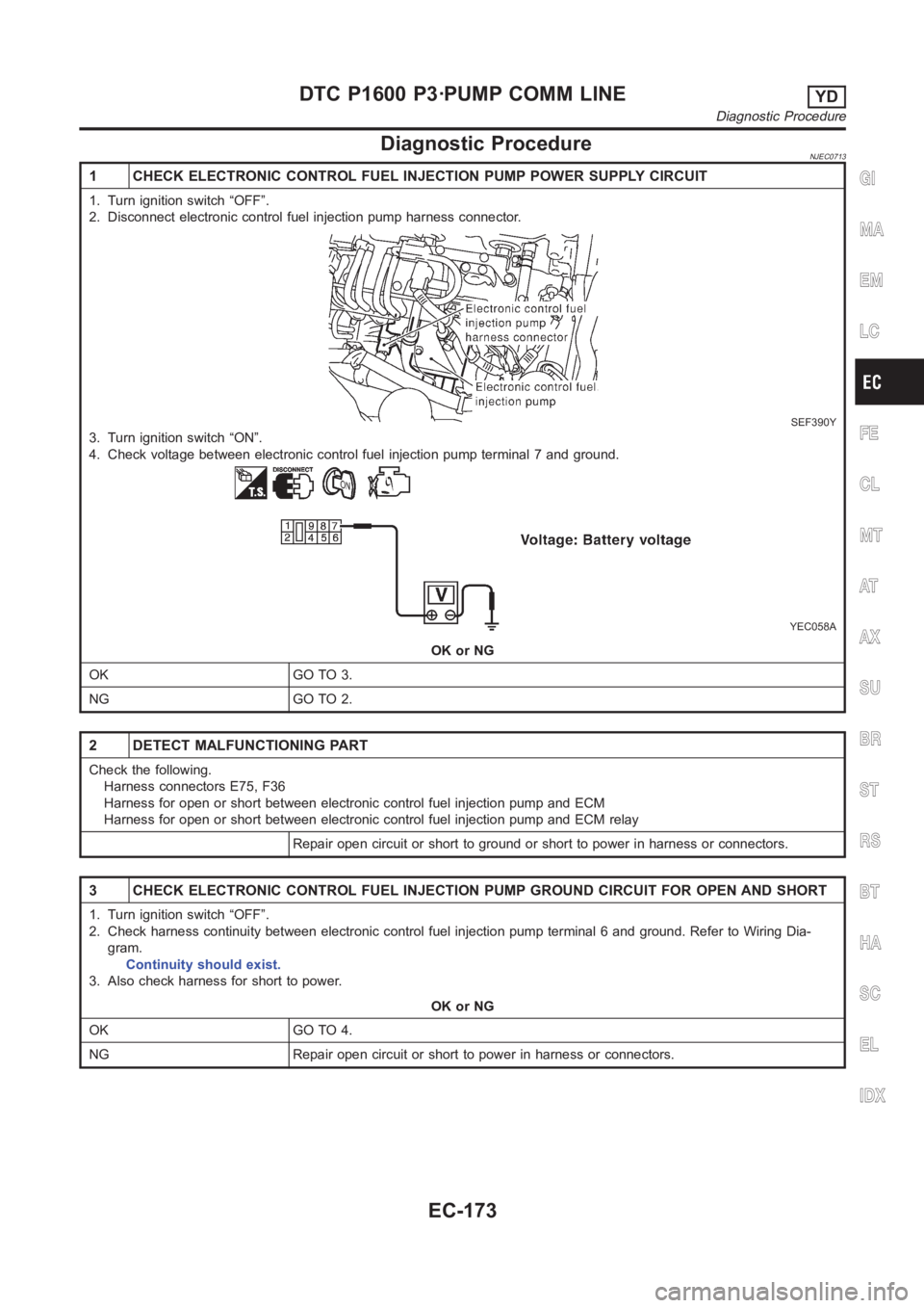
1 CHECK ELECTRONIC CONTROL FUEL INJECTION PUMP POWER SUPPLY CIRCUIT
1. Turn ignition switch “OFF”.
2. Disconnect electronic control fuel injection pump harness connector.
SEF390Y
3. Turn ignition switch “ON”.
4. Check voltage between electronic control fuel injection pump terminal7 and ground.
YEC058A
OK or NG
OK GO TO 3.
NG GO TO 2.
2 DETECT MALFUNCTIONING PART
Check the following.
Harness connectors E75, F36
Harness for open or short between electronic control fuel injection pump and ECM
Harness for open or short between electronic control fuel injection pump and ECM relay
Repair open circuit or short to ground or short to power in harness or connectors.
3 CHECK ELECTRONIC CONTROL FUEL INJECTION PUMP GROUND CIRCUIT FOR OPEN ANDSHORT
1. Turn ignition switch “OFF”.
2. Check harness continuity between electronic control fuel injection pump terminal 6 and ground. Refer to Wiring Dia-
gram.
Continuity should exist.
3. Also check harness for short to power.
OK or NG
OK GO TO 4.
NG Repair open circuit or short to power in harness or connectors.
GI
MA
EM
LC
FE
CL
MT
AT
AX
SU
BR
ST
RS
BT
HA
SC
EL
IDX
DTC P1600 P3·PUMP COMM LINEYD
Diagnostic Procedure
EC-173
Page 1229 of 3189

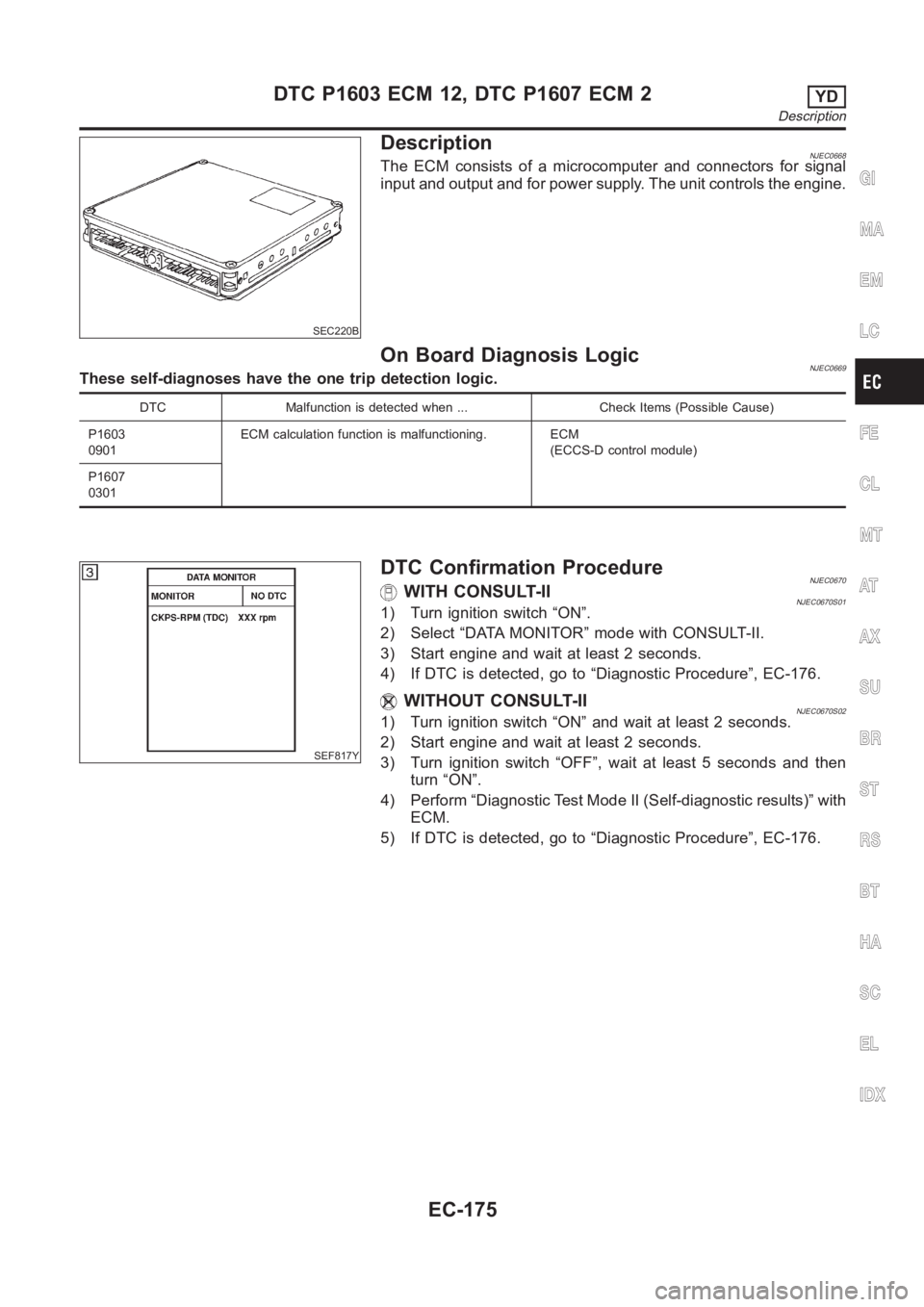
SEC220B
DescriptionNJEC0668The ECM consists of a microcomputer and connectors for signal
input and output and for power supply. The unit controls the engine.
On Board Diagnosis LogicNJEC0669These self-diagnoses have the one trip detection logic.
DTC Malfunction is detected when ... Check Items (Possible Cause)
P1603
0901ECM calculation function is malfunctioning. ECM
(ECCS-D control module)
P1607
0301
SEF817Y
DTC Confirmation ProcedureNJEC0670WITH CONSULT-IINJEC0670S011) Turn ignition switch “ON”.
2) Select “DATA MONITOR” mode with CONSULT-II.
3) Start engine and wait at least 2 seconds.
4) If DTC is detected, go to “Diagnostic Procedure”, EC-176.
WITHOUT CONSULT-IINJEC0670S021) Turn ignition switch “ON” and wait at least 2 seconds.
2) Start engine and wait at least 2 seconds.
3) Turn ignition switch “OFF”, wait at least 5 seconds and then
turn “ON”.
4) Perform “Diagnostic Test Mode II (Self-diagnostic results)” with
ECM.
5) If DTC is detected, go to “Diagnostic Procedure”, EC-176.
GI
MA
EM
LC
FE
CL
MT
AT
AX
SU
BR
ST
RS
BT
HA
SC
EL
IDX
DTC P1603 ECM 12, DTC P1607 ECM 2YD
Description
EC-175
Page 1230 of 3189
Diagnostic ProcedureNJEC0671
1 INSPECTION START
With CONSULT-II
1. Turn ignition switch “ON”.
2. Select “SELF DIAG RESULTS” mode with CONSULT-II.
3. Touch “ERASE”.
4. Perform “DTC Confirmation Procedure”, EC-175, again.
5. Is the DTC P1603 or P1607 displayed again?
Without CONSULT-II
1. Turn ignition switch “ON”.
2. Erase the Diagnostic Test Mode II (Self-diagnostic results) memory.
3. Perform “DTC Confirmation Procedure”, EC-175, again.
4. Perform “Diagnostic Test Mode II (Self-diagnostic results)”.
5. Is the DTC 0301 or 0901 displayed again?
YesorNo
Yes Replace ECM.
NoINSPECTION END
DTC P1603 ECM 12, DTC P1607 ECM 2YD
Diagnostic Procedure
EC-176
Page 1231 of 3189

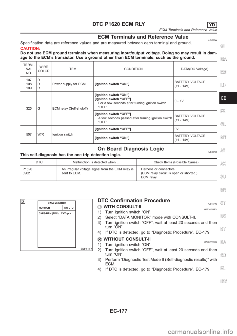
ECM Terminals and Reference ValueNJEC0744Specification data are reference values and are measured between each terminal and ground.
CAUTION:
Do not use ECM ground terminals when measuring input/output voltage. Doing so may result in dam-
age to the ECM’s transistor. Use a ground other than ECM terminals, such as the ground.
TERMI-
NAL
NO.WIRE
COLORITEM CONDITION DATA(DC Voltage)
107
108
109R
R
RPower supply for ECM[Ignition switch “ON”]BATTERY VOLTAGE
(11 - 14V)
325 G ECM relay (Self-shutoff)[Ignition switch “ON”]
[Ignition switch “OFF”]
For a few seconds after turning ignition switch
“OFF”0-1V
[Ignition switch “OFF”]
A few seconds passed after turning ignition switch
“OFF”BATTERY VOLTAGE
(11 - 14V)
507 W/R Ignition switch[Ignition switch “OFF”]0V
[Ignition switch “ON”]BATTERY VOLTAGE
(11 - 14V)
On Board Diagnosis LogicNJEC0745This self-diagnosis has the one trip detection logic.
DTC Malfunction is detected when .... Check Items (Possible Cause)
P1620
0902An irregular voltage signal from the ECM relay is
sent to ECM.Harness or connectors
(ECM relay circuit is open or shorted.)
ECM relay
SEF817Y
DTC Confirmation ProcedureNJEC0746WITH CONSULT-IINJEC0746S011) Turn ignition switch “ON”.
2) Select “DATA MONITOR” mode with CONSULT-II.
3) Turn ignition switch “OFF”, wait at least 20 seconds and then
turn “ON”.
4) If DTC is detected, go to “Diagnostic Procedure”, EC-179.
WITHOUT CONSULT-IINJEC0746S021) Turn ignition switch “ON”.
2) Turn ignition switch “OFF”, wait at least 20 seconds and then
turn “ON”.
3) Perform “Diagnostic Test Mode II (Self-diagnostic results)” with
ECM.
4) If DTC is detected, go to “Diagnostic Procedure”, EC-179.
GI
MA
EM
LC
FE
CL
MT
AT
AX
SU
BR
ST
RS
BT
HA
SC
EL
IDX
DTC P1620 ECM RLYYD
ECM Terminals and Reference Value
EC-177
Page 1232 of 3189
Wiring DiagramNJEC0747
YEC327A
DTC P1620 ECM RLYYD
Wiring Diagram
EC-178
Page 1233 of 3189

Diagnostic ProcedureNJEC0748
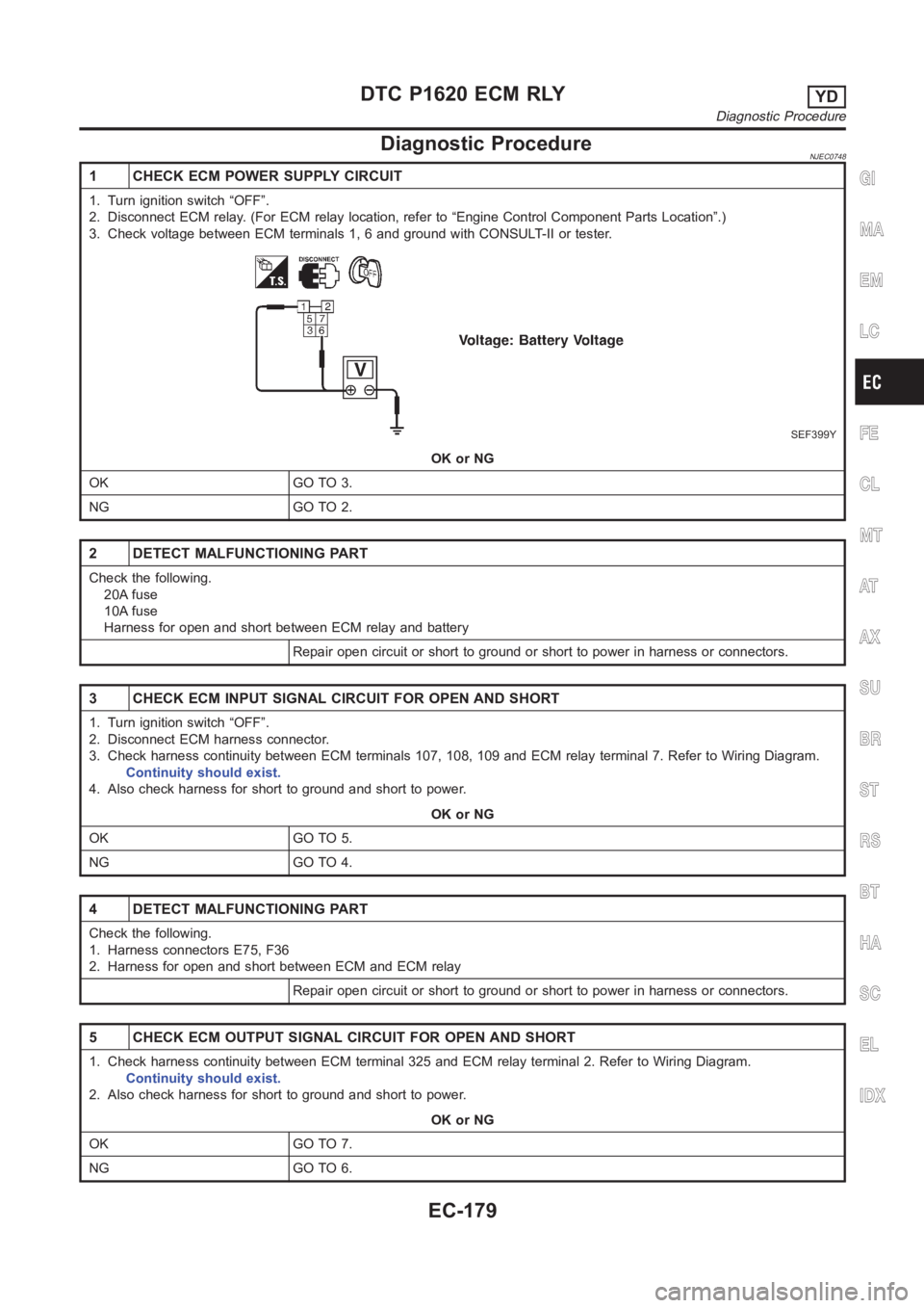
1 CHECK ECM POWER SUPPLY CIRCUIT
1. Turn ignition switch “OFF”.
2. Disconnect ECM relay. (For ECM relay location, refer to “Engine ControlComponent Parts Location”.)
3. Check voltage between ECM terminals 1, 6 and ground with CONSULT-II or tester.
SEF399Y
OK or NG
OK GO TO 3.
NG GO TO 2.
2 DETECT MALFUNCTIONING PART
Check the following.
20A fuse
10A fuse
Harness for open and short between ECM relay and battery
Repair open circuit or short to ground or short to power in harness or connectors.
3 CHECK ECM INPUT SIGNAL CIRCUIT FOR OPEN AND SHORT
1. Turn ignition switch “OFF”.
2. Disconnect ECM harness connector.
3. Check harness continuity between ECM terminals 107, 108, 109 and ECM relay terminal 7. Refer to Wiring Diagram.
Continuity should exist.
4. Also check harness for short to ground and short to power.
OK or NG
OK GO TO 5.
NG GO TO 4.
4 DETECT MALFUNCTIONING PART
Check the following.
1. Harness connectors E75, F36
2. Harness for open and short between ECM and ECM relay
Repair open circuit or short to ground or short to power in harness or connectors.
5 CHECK ECM OUTPUT SIGNAL CIRCUIT FOR OPEN AND SHORT
1. Check harness continuity between ECM terminal 325 and ECM relay terminal 2. Refer to Wiring Diagram.
Continuity should exist.
2. Also check harness for short to ground and short to power.
OK or NG
OK GO TO 7.
NG GO TO 6.
GI
MA
EM
LC
FE
CL
MT
AT
AX
SU
BR
ST
RS
BT
HA
SC
EL
IDX
DTC P1620 ECM RLYYD
Diagnostic Procedure
EC-179
Page 1234 of 3189
6 DETECT MALFUNCTIONING PART
Check the following.
Harness connectors E174, M159 (LHD models)
Harness connectors E251, M182 (RHD models)
Harness connectors M63, F102
Harness for open and short between ECM and ECM relay
Repair open circuit or short to ground or short to power in harness or connectors.
7 CHECK ECM RELAY
1. Apply 12V direct current between ECM relay terminals 1 and 2.
2. Check continuity between ECM relay terminals 3 and 5, 6 and 7.
SEF296X
OK or NG
OK GO TO 8.
NG Replace ECM relay.
8 CHECK INTERMITTENT INCIDENT
Refer to “TROUBLE DIAGNOSIS FOR INTERMITTENT INCIDENT”, EC-71.
INSPECTION END
DTC P1620 ECM RLYYD
Diagnostic Procedure (Cont’d)
EC-180