Page 201 of 3189
JEM116G
13. For Europe only, remove catalyst rear diffuser, EM-36, “Cata-
lyst (For Europe)”.
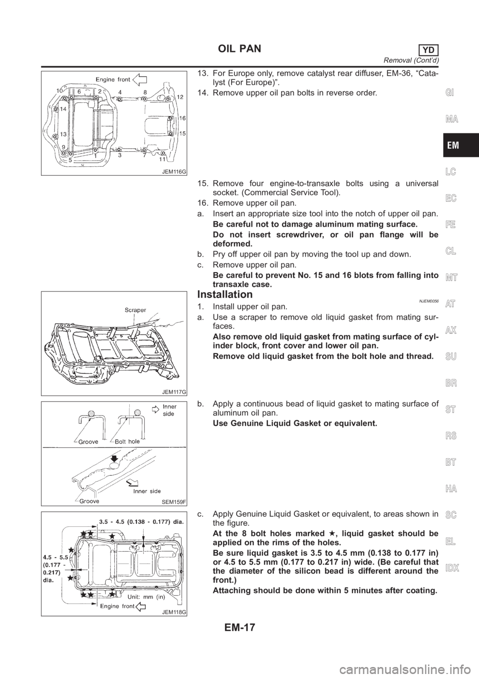
14. Remove upper oil pan bolts in reverse order.
15. Remove four engine-to-transaxle bolts using a universal
socket. (Commercial Service Tool).
16. Remove upper oil pan.
a. Insert an appropriate size tool into the notch of upper oil pan.
Be careful not to damage aluminum mating surface.
Do not insert screwdriver, or oil pan flange will be
deformed.
b. Pry off upper oil pan by moving the tool up and down.
c. Remove upper oil pan.
Be careful to prevent No. 15 and 16 blots from falling into
transaxle case.
JEM117G
InstallationNJEM00561. Install upper oil pan.
a. Use a scraper to remove old liquid gasket from mating sur-
faces.
Also remove old liquid gasket from mating surface of cyl-
inder block, front cover and lower oil pan.
Remove old liquid gasket from the bolt hole and thread.
SEM159F
b. Apply a continuous bead of liquid gasket to mating surface of
aluminum oil pan.
Use Genuine Liquid Gasket or equivalent.
JEM118G
c. Apply Genuine Liquid Gasket or equivalent, to areas shown in
the figure.
At the 8 bolt holes marked★, liquid gasket should be
applied on the rims of the holes.
Be sure liquid gasket is 3.5 to 4.5 mm (0.138 to 0.177 in)
or 4.5 to 5.5 mm (0.177 to 0.217 in) wide. (Be careful that
the diameter of the silicon bead is different around the
front.)
Attaching should be done within 5 minutes after coating.
GI
MA
LC
EC
FE
CL
MT
AT
AX
SU
BR
ST
RS
BT
HA
SC
EL
IDX
OIL PANYD
Removal (Cont’d)
EM-17
Page 202 of 3189
JEM116G
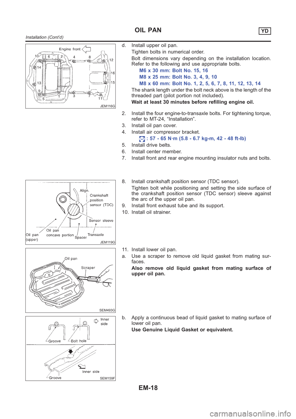
d. Install upper oil pan.
Tighten bolts in numerical order.
Bolt dimensions vary depending on the installation location.
Refer to the following and use appropriate bolts.
M6 x 30 mm: Bolt No. 15, 16
M8x25mm:BoltNo.3,4,9,10
M8x60mm:BoltNo.1,2,5,6,7,8,11,12,13,14
The shank length under the bolt neck above is the length of the
threaded part (pilot portion not included).
Wait at least 30 minutes before refilling engine oil.
2. Install the four engine-to-transaxle bolts. For tightening torque,
refer to MT-24, “Installation”.
3. Install oil pan cover.
4. Install air compressor bracket.
: 57 - 65 N·m (5.8 - 6.7 kg-m, 42 - 48 ft-lb)
5. Install drive belts.
6. Install center member.
7. Install front and rear engine mounting insulator nuts and bolts.
JEM119G
8. Install crankshaft position sensor (TDC sensor).
Tighten bolt while positioning and setting the side surface of
the crankshaft position sensor (TDC sensor) sleeve against
the arc of the upper oil pan.
9. Install front exhaust tube and its support.
10. Install oil strainer.
SEM493G
11. Install lower oil pan.
a. Use a scraper to remove old liquid gasket from mating sur-
faces.
Also remove old liquid gasket from mating surface of
upper oil pan.
SEM159F
b. Apply a continuous bead of liquid gasket to mating surface of
lower oil pan.
Use Genuine Liquid Gasket or equivalent.
OIL PANYD
Installation (Cont’d)
EM-18
Page 210 of 3189
REMOVALNJEM0094S011. Remove engine and transaxle assembly. Refer to EM-63,
“ENGINE ASSEMBLY”.
2. Remove transaxle from engine. Place engine onto engine
stand (SST). Refer to EM-67, “CYLINDER BLOCK”, “Disas-
sembly”.
3. Remove the following parts:
Oil pan (upper and lower)
Refer to EM-15, “OIL PAN”.
Oil filter bracket
Refer to LC-31, “Oil Filter Bracket”.
Injection tube
Refer to EC-21, “Injection Tube and Injection Nozzle”.
4. Remove secondary timing chain and associated parts.
Refer to EM-20, “Secondary Timing Chain”.
5. When removing rear chain case, remove camshaft sprockets.
Refer to EM-46, “CAMSHAFT”.
JEM131G
6. Remove crankshaft pulley.
a. Hold crankshaft pulley with the pulley holder (SST).
b. Loosen crankshaft pulley fixing bolt and pull out the bolt
approximately 10 mm (0.39 in).
JEM132G
c. Using pulley puller (SST), remove crankshaft pulley.
Use two M6 bolts with approx. 60 mm (2.36 in) shank length
for securing crankshaft pulley.
JEM133G
7. Remove oil pump.
Loosen bolts in the reverse order of that shown in the figure
and remove them.
Use seal cutter (SST) etc. for removal.
8. Remove front oil seal from oil pump.
Punch out the seal off from the back surface of the oil pump
using a flat-bladed screwdriver.
Be careful not to damage the oil pump.
TIMING CHAINYD
Primary Timing Chain (Cont’d)
EM-26
Page 216 of 3189
JEM147G
15. Install crankshaft pulley.
a. Install crankshaft pulley to crankshaft.
b. Hold crankshaft pulley with the pulley holder (SST).
c. Tighten bolt to 20 to 29 N·m (2.0 to 3.0 kg-m, 15 to 21 ft-lb).
d. Put an alignment mark on crankshaft pulley that aligns with
one of the punched marks on the bolt.
e. Tighten fixing bolt another 60° - 66° [target: 60° (turn by one
notch)].
16. Install secondary timing chain and the associated parts.
Refer to EM-22, “Secondary Timing Chain”, “INSTALLATION”.
17. Install in the reverse order of removal hereafter.
TIMING CHAINYD
Primary Timing Chain (Cont’d)
EM-32
Page 220 of 3189
Removal and InstallationNJEM0101
JEM264G
PREPARATIVE WORKNJEM0101S01Remove the following parts.
Under cover
Engine coolant (drain)
Refer to LC-43, “Changing Engine Coolant”.
Radiator upper hose
Cooling fan
Refer to LC-42, “Radiator”.
Radiator mount bracket
Water inlet pipe
Exhaust front tube (disconnect)
Refer to FE-26, “Removal and Installation”, “EXHAUST SYS-
TEM”.
CATALYSTNJEM0101S02RemovalNJEM0101S0201Remove the catalyst, refer to above illustration.
CAUTION:
Do not disassemble.
InstallationNJEM0101S0202Install two locking pins into both sides of the catalytic converter. Be
careful not to confuse locking pins with insulator mounting bolts.
Catalytic converter locking pin:
Flange bolt (black)
Insulator mounting bolt:
Washer bolt (silver or yellow)
CATALYSTYD
Removal and Installation
EM-36
Page 230 of 3189
CAUTION:
When installing camshafts, chain tensioners, oil seals, or
other sliding parts, lubricate contacting surfaces with new
engine oil.
Apply new engine oil to threads and seat surfaces when
installing cylinder head, camshaft sprocket, crankshaft
pulley, and camshaft bracket.
Attach tags to valve lifters so as not to mix them up.
RemovalNJEM0063PREPARATIVE WORKNJEM0063S011. Drain engine coolant. Refer to LC-43, “Changing Engine Cool-
ant”.
2. Remove exhaust manifold. Refer to EM-38, “Removal”.
3. Remove intake manifold. Refer to EM-34, “Removal”.
Apply paint to camshaft sprockets for alignment during
installation.
JEM152G
CAMSHAFTNJEM0063S021. Remove the following parts:
Rocker cover
Vacuum pump and cylinder head rear cover assembly
Spill tube
High pressure injection nozzle assembly
Secondary timing chain and associated parts
JEM159G
2. Remove camshaft sprockets.
Holding the hexagonal part of the camshaft with a wrench
having 21 mm (0.83 in) width between facing flats, loosen the
bolt holding the camshaft sprocket.
JEM160G
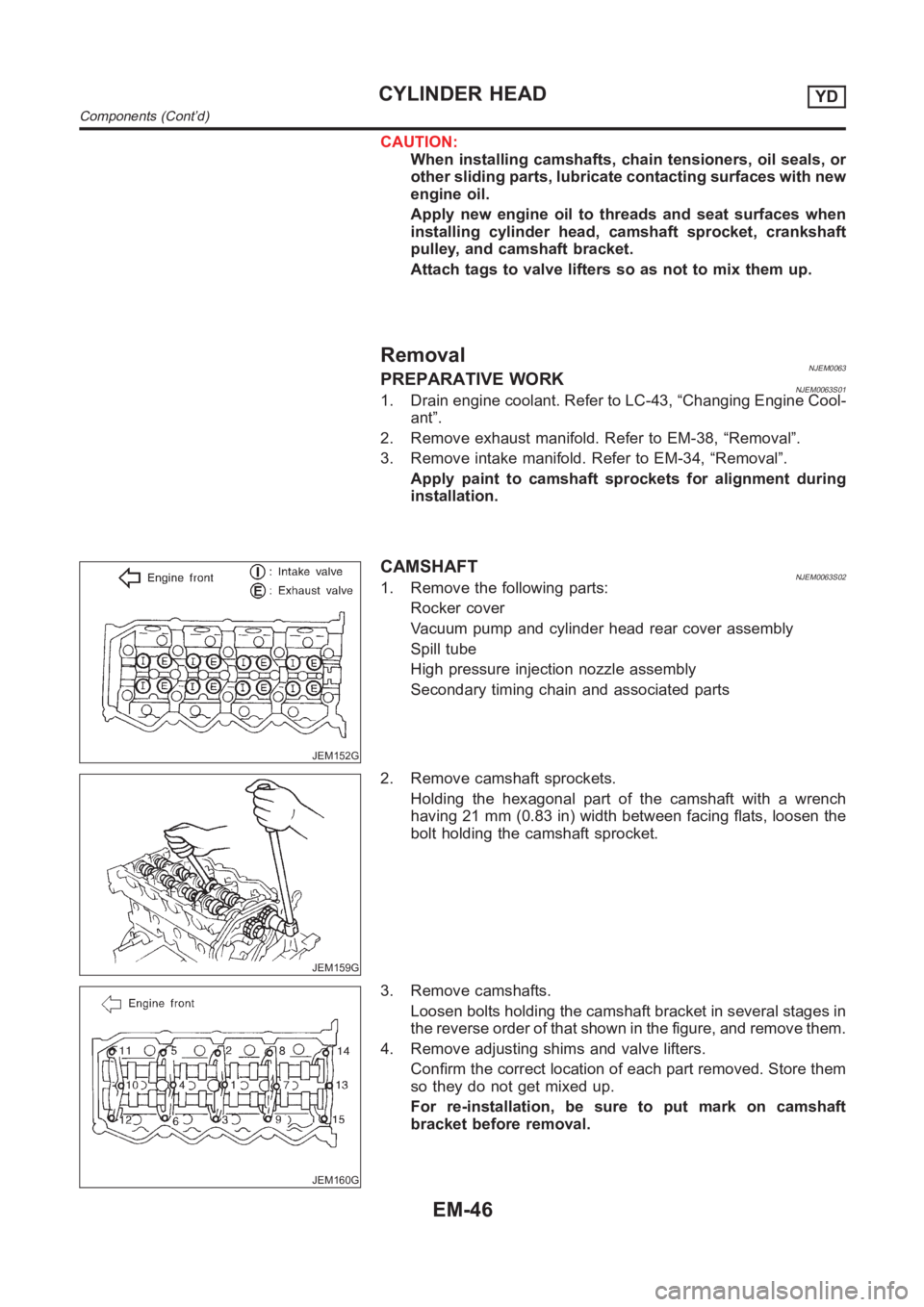
3. Remove camshafts.
Loosen bolts holding the camshaft bracket in several stages in
the reverse order of that shown in the figure, and remove them.
4. Remove adjusting shims and valve lifters.
Confirm the correct location of each part removed. Store them
so they do not get mixed up.
For re-installation, be sure to put mark on camshaft
bracket before removal.
CYLINDER HEADYD
Components (Cont’d)
EM-46
Page 240 of 3189
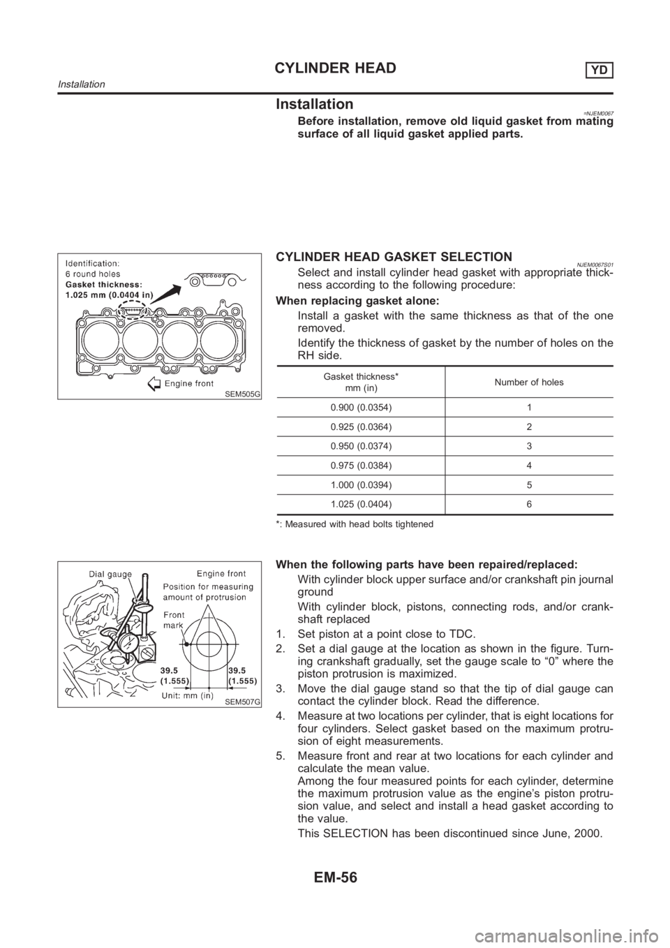
Installation=NJEM0067Before installation, remove old liquid gasket from mating
surface of all liquid gasket applied parts.
SEM505G
CYLINDER HEAD GASKET SELECTIONNJEM0067S01Select and install cylinder head gasket with appropriate thick-
ness according to the following procedure:
When replacing gasket alone:
Install a gasket with the same thickness as that of the one
removed.
Identify the thickness of gasket by the number of holes on the
RH side.
Gasket thickness*
mm (in)Number of holes
0.900 (0.0354) 1
0.925 (0.0364) 2
0.950 (0.0374) 3
0.975 (0.0384) 4
1.000 (0.0394) 5
1.025 (0.0404) 6
*: Measured with head bolts tightened
SEM507G
When the following parts have been repaired/replaced:
With cylinder block upper surface and/or crankshaft pin journal
ground
With cylinder block, pistons, connecting rods, and/or crank-
shaft replaced
1. Set piston at a point close to TDC.
2. Set a dial gauge at the location as shown in the figure. Turn-
ing crankshaft gradually, set the gauge scale to “0” where the
piston protrusion is maximized.
3. Move the dial gauge stand so that the tip of dial gauge can
contact the cylinder block. Read the difference.
4. Measure at two locations per cylinder, that is eight locations for
four cylinders. Select gasket based on the maximum protru-
sion of eight measurements.
5. Measure front and rear at two locations for each cylinder and
calculate the mean value.
Among the four measured points for each cylinder, determine
the maximum protrusion value as the engine’s piston protru-
sion value, and select and install a head gasket according to
the value.
This SELECTION has been discontinued since June, 2000.
CYLINDER HEADYD
Installation
EM-56
Page 248 of 3189

crankshaft position sensor (TDC sensor) from the assem-
bly.
Always pay extra attention not to damage edge of crank-
shaft position sensor (TDC sensor) or ring gear teeth.
REMOVALNJEM0069S011. Remove engine undercover, and hood for hoisting.
2. Drain coolant from both cylinder block and radiator. Refer to
LC-43, “Changing Engine Coolant”.
3. Remove the following parts:
Battery
RH and LH front wheels
RH and LH splash covers (combined with undercover)
Auxiliary belts
Alternator
Alternator brackets
Radiator and cooling fan
Engine cover
Air ducts and air cleaner case
LH side of engine room:
4. Disconnect all harnesses and grounds that are connected to
components on vehicle.
5. Disconnect vacuum hose on vacuum pump side.
6. Disconnect fuel feed and fuel return hoses on engine side.
Immediately put blind plugs into the openings to prevent
fuel from flowing out.
7. Disconnect heater hose. Plug opening of hose to prevent cool-
ant from flowing out.
RH side of engine room:
8. Remove air conditioner compressor from brackets and move
it toward vehicle side. Secure compressor on vehicle side with
rope.
Vehicle underside:
9. Remove exhaust front tube.
10. Disconnect two hoses from power steering pump and plug to
stop fluid.
11. Remove M/T control rod and support rod.
12. Remove ABS wheel sensor, and temporarily hang brake cali-
per with rope on vehicle side.
13. Remove RH and LH drive shafts.
YEM024
14. Install engine slingers to cylinder head.
: 30 - 37 N·m (3.0 - 3.8 kg-m, 22 - 27 ft-lb)
Use engine slingers and securing bolts of the specified
service parts.
15. Lift up vehicle to appropriate level where work can be per-
formed efficiently. Using two transmission jacks, securely sup-
port engine oil pan and bottom surface of transaxle.
ENGINE ASSEMBLYYD
Removal and Installation (Cont’d)
EM-64