Page 71 of 3189

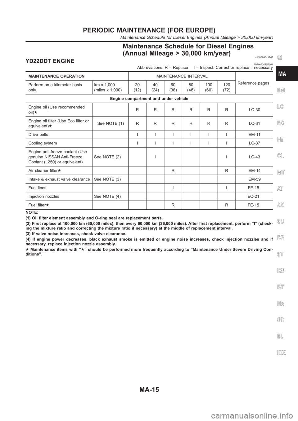
Maintenance Schedule for Diesel Engines
(Annual Mileage > 30,000 km/year)
=NJMA0043S05YD22DDT ENGINENJMA0043S0501Abbreviations: R = Replace I = Inspect: Correct or replace if necessary
MAINTENANCE OPERATIONMAINTENANCE INTERVAL
Reference pages
Perform on a kilometer basis
only.kmx1,000
(miles x 1,000)20
(12)40
(24)60
(36)80
(48)100
(60)120
(72)
Engine compartment and under vehicle
Engine oil (Use recommended
oil)★RRRRRR LC-30
Engine oil filter (Use Eco filter or
equivalent)★SeeNOTE(1)RRRRRR LC-31
Drive beltsIIIIIIEM-11
Cooling systemIIIIII LC-37
Engine anti-freeze coolant (Use
genuine NISSAN Anti-Freeze
Coolant (L250) or equivalent)See NOTE (2) I I LC-43
Air cleaner filter★R R EM-14
Intake & exhaust valve clearance See NOTE (3) EM-59
Fuel lines I I FE-15
Injection nozzles See NOTE (4) EC-21
Fuel filter★R R FE-15
NOTE:
(1) Oil filter element assembly and O-ring seal are replacement parts.
(2) First replace at 100,000 km (60,000 miles), then every 60,000 km (36,000 miles). After first replacement, perform “I” (check-
ing the mixture ratio and correcting the mixture ratio if necessary) at themiddle of replacement interval.
(3) If valve noise increases, check valve clearance.
(4) If engine power decreases, black exhaust smoke is emitted or engine noise increases, check injection nozzles and if
necessary, replace injection nozzle assembly.
★Maintenance items with “★” should be performed more frequently according to “Maintenance Under Severe Driving Con-
ditions”.
GI
EM
LC
EC
FE
CL
MT
AT
AX
SU
BR
ST
RS
BT
HA
SC
EL
IDX
PERIODIC MAINTENANCE (FOR EUROPE)
Maintenance Schedule for Diesel Engines (Annual Mileage > 30,000 km/year)
MA-15
Page 72 of 3189

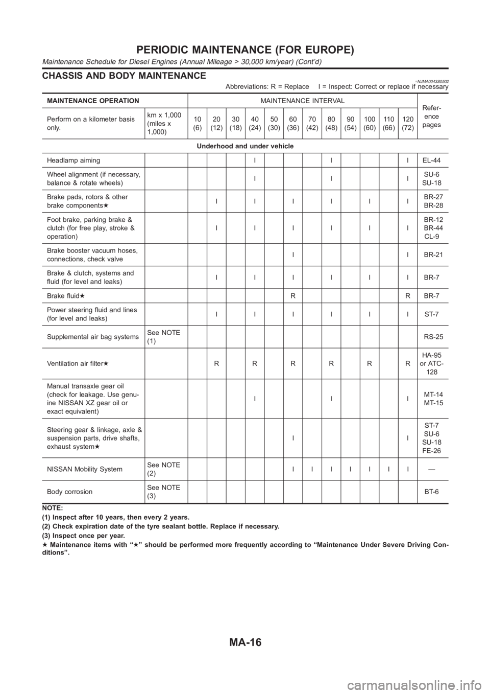
CHASSIS AND BODY MAINTENANCE=NJMA0043S0502Abbreviations: R = Replace I = Inspect: Correct or replace if necessary
MAINTENANCE OPERATIONMAINTENANCE INTERVAL
Refer-
ence
pages Perform on a kilometer basis
only.kmx1,000
(miles x
1,000)10
(6)20
(12)30
(18)40
(24)50
(30)60
(36)70
(42)80
(48)90
(54)100
(60)11 0
(66)120
(72)
Underhood and under vehicle
Headlamp aiming I I I EL-44
Wheel alignment (if necessary,
balance & rotate wheels)IIISU-6
SU-18
Brake pads, rotors & other
brake components★IIIIIIBR-27
BR-28
Foot brake, parking brake &
clutch (for free play, stroke &
operation)IIIIIIBR-12
BR-44
CL-9
Brake booster vacuum hoses,
connections, check valveI I BR-21
Brake & clutch, systems and
fluid (for level and leaks)IIIIIIBR-7
Brake fluid★R R BR-7
Power steering fluid and lines
(for level and leaks)IIIIIIST-7
Supplemental air bag systemsSee NOTE
(1)RS-25
Ventilation air filter★RRRRRRHA-95
or ATC-
128
Manual transaxle gear oil
(check for leakage. Use genu-
ine NISSAN XZ gear oil or
exact equivalent)IIIMT-14
MT-15
Steering gear & linkage, axle &
suspension parts, drive shafts,
exhaust system★IIST-7
SU-6
SU-18
FE-26
NISSAN Mobility SystemSee NOTE
(2)IIIIIII —
Body corrosionSee NOTE
(3)BT-6
NOTE:
(1) Inspect after 10 years, then every 2 years.
(2) Check expiration date of the tyre sealant bottle. Replace if necessary.
(3) Inspect once per year.
★Maintenance items with “★” should be performed more frequently according to “Maintenance Under Severe Driving Con-
ditions”.
PERIODIC MAINTENANCE (FOR EUROPE)
Maintenance Schedule for Diesel Engines (Annual Mileage > 30,000 km/year) (Cont’d)
MA-16
Page 77 of 3189

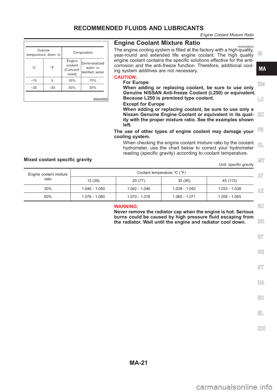
SMA089D
Engine Coolant Mixture Ratio=NJMA0006S03The engine cooling system is filled at the factory with a high-quality,
year-round and extended life engine coolant. The high quality
engine coolant contains the specific solutions effective for the anti-
corrosion and the anti-freeze function. Therefore, additional cool-
ing system additives are not necessary.
CAUTION:
For Europe
When adding or replacing coolant, be sure to use only
Genuine NISSAN Anti-freeze Coolant (L250) or equivalent.
Because L250 is premixed type coolant.
Except for Europe
When adding or replacing coolant, be sure to use only a
Nissan Genuine Engine Coolant or equivalent in its qual-
ity with the proper mixture ratio. See the examples shown
left.
The use of other types of engine coolant may damage your
cooling system.
When checking the engine coolant mixture ratio by the coolant
hydrometer, use the chart below to correct your hydrometer
reading (specific gravity) according to coolant temperature.
Mixed coolant specific gravity
Unit: specific gravity
Engine coolant mixture
ratioCoolant temperature °C (°F)
15 (59) 25 (77) 35 (95) 45 (113)
30% 1.046 - 1.050 1.042 - 1.046 1.038 - 1.042 1.033 - 1.038
50% 1.076 - 1.080 1.070 - 1.076 1.065 - 1.071 1.059 - 1.065
WARNING:
Never remove the radiator cap when the engine is hot. Serious
burns could be caused by high pressure fluid escaping from
the radiator. Wait until the engine and radiator cool down.
GI
EM
LC
EC
FE
CL
MT
AT
AX
SU
BR
ST
RS
BT
HA
SC
EL
IDX
RECOMMENDED FLUIDS AND LUBRICANTS
Engine Coolant Mixture Ratio
MA-21
Page 89 of 3189
![NISSAN ALMERA N16 2003 Electronic Repair Manual DRIVE BELTS
EM-11
[QG]
C
D
E
F
G
H
I
J
K
L
MA
EM
DRIVE BELTSPFP:02117
Checking Drive BeltsEBS00LPY
●Before inspecting the engine, make sure the engine has cooled down; wait approximately NISSAN ALMERA N16 2003 Electronic Repair Manual DRIVE BELTS
EM-11
[QG]
C
D
E
F
G
H
I
J
K
L
MA
EM
DRIVE BELTSPFP:02117
Checking Drive BeltsEBS00LPY
●Before inspecting the engine, make sure the engine has cooled down; wait approximately](/manual-img/5/57350/w960_57350-88.png)
DRIVE BELTS
EM-11
[QG]
C
D
E
F
G
H
I
J
K
L
MA
EM
DRIVE BELTSPFP:02117
Checking Drive BeltsEBS00LPY
●Before inspecting the engine, make sure the engine has cooled down; wait approximately 30 minutes
after the engine has been stopped.
●Visually inspect all belts for wear, damage, or cracks on contacting surfaces and edge areas.
●When measuring deflection, apply 98 N (10 kg, 22 lb) at the ▼ marked point.
CAUTION:
When measuring belt tension immediately after belt is installed, first set the tension to the standard.
Then, rotate crankshaft for more than two turns in order to eliminate variance in belt deflection
between the pulleys. Re-measure and adjust the tension to the standard.
PBIC0764E
Deflection adjustment Unit: mm (in)
Used belt
New belt
Limit After adjustment
AlternatorWithout air conditioner compressor 10.2 (0.402)6.5 - 7.0
(0.256 - 0.276)5.5 - 6.1
(0.217 - 0.240)
With air conditioner compressor 8.1 (0.319)5.3 - 5.7
(0.209 - 0.224)4.5 - 5.0
(0.177 - 0.197)
Power steering oil pump 7.1 (0.280)4.4 - 4.9
(0.173 - 0.193)3.9 - 4.4
(0.154 - 0.173)
Applied pushing force 98 N (10 kg, 22 lb)
Page 91 of 3189
DRIVE BELTS
EM-13
[QG]
C
D
E
F
G
H
I
J
K
L
MA
EM
Removal and InstallationEBS00LQ0
REMOVAL
●Loosen each belt while referring to “Tension Adjustment”, and remove them one by one starting from the
one in front.
INSTALLATION
1. Install belts to pulley in reverse order of removal.
2. Adjust belt tension.
CAUTION:
●When checking belt tension immediately after installation, first, adjust to specified value. Then,
after turning crankshaft more than two turns, re-adjust to specified value to avoid variation in
deflection between pulleys.
●Tighten idler pulley lock nut by hand and measure tension without looseness.
3. Tighten each adjusting bolt and nut to the specified torque.
4. Make sure that tension of each belt is within the standard.
Page 105 of 3189
![NISSAN ALMERA N16 2003 Electronic Repair Manual FUEL INJECTOR AND FUEL TUBE
EM-27
[QG]
C
D
E
F
G
H
I
J
K
L
MA
EM
CAUTION:
Do not touch fuel injector nozzle with intake manifold or other parts.
5. Remove fuel injector from fuel tube.
●Release clip NISSAN ALMERA N16 2003 Electronic Repair Manual FUEL INJECTOR AND FUEL TUBE
EM-27
[QG]
C
D
E
F
G
H
I
J
K
L
MA
EM
CAUTION:
Do not touch fuel injector nozzle with intake manifold or other parts.
5. Remove fuel injector from fuel tube.
●Release clip](/manual-img/5/57350/w960_57350-104.png)
FUEL INJECTOR AND FUEL TUBE
EM-27
[QG]
C
D
E
F
G
H
I
J
K
L
MA
EM
CAUTION:
Do not touch fuel injector nozzle with intake manifold or other parts.
5. Remove fuel injector from fuel tube.
●Release clip and remove it.
●Pull fuel injector straight out of fuel tube.
CAUTION:
●Be careful not to damage nozzle part.
●Avoid any impact such as a dropping.
●Do not disassemble or adjust it.
INSTALLATION
1. When installing O-ring to fuel injector, follow instructions described below.
CAUTION:
●Handle O-ring with bare hands. Never wear gloves.
●Lubricate O-ring with new engine oil.
●Do not clean O-ring with solvent.
●Make sure that O-ring and its mating part are free of foreign material.
●Be careful not to scratch it with a tool or fingernails during installation. Also be careful not to
twist or stretch O-ring. If O-ring is stretched while being attached, do not insert it into fuel tube
immediately.
●Insert O-ring straight into fuel tube. Do not angle or twist it.
2.
Install fuel injector to fuel tube with the following procedure.
a. Insert clip into clip mounting groove on fuel injector.
●Insert clip so that lug “A” of fuel injector matches notch “A” of
the clip.
CAUTION:
●Do not reuse clip. Replace it with a new one.
●Be careful to keep clip from interfering with O-ring. If
interference occurs, replace O-ring.
b. Insert fuel injector into fuel tube with clip attached.
●Insert it while matching it to the axial center.
●Insert fuel injector so that lug “B” of fuel tube matches notch
“B” of the clip.
●Make sure that fuel tube flange is securely fixed in flange fix-
ing groove on clip.
c. Make sure that installation is complete by checking that fuel
injector does not rotate or come off.
PBIC0620E
PBIC1021E
Page 114 of 3189
![NISSAN ALMERA N16 2003 Electronic Repair Manual EM-36
[QG]
CAMSHAFT
2. Install camshaft.
●Intake and exhaust camshafts are distinguished by checking
difference between front and rear end shapes.
NOTE:
Some exhaust camshafts have a groove on the r NISSAN ALMERA N16 2003 Electronic Repair Manual EM-36
[QG]
CAMSHAFT
2. Install camshaft.
●Intake and exhaust camshafts are distinguished by checking
difference between front and rear end shapes.
NOTE:
Some exhaust camshafts have a groove on the r](/manual-img/5/57350/w960_57350-113.png)
EM-36
[QG]
CAMSHAFT
2. Install camshaft.
●Intake and exhaust camshafts are distinguished by checking
difference between front and rear end shapes.
NOTE:
Some exhaust camshafts have a groove on the rear end.
●Install camshafts so that dowel pins on their front ends are
positioned as shown.
3. Install camshaft brackets.
●Completely remove any foreign material on back surfaces of
camshaft brackets and top surface of cylinder head.
●Referring to marks on top surfaces of camshaft brackets,
install them to their original positions and in their original
directions.
4. Tighten camshaft bracket mounting bolts as follows:
a. Different bolts are used depending on installation location. Refer
to following and install appropriate bolts.
b. First tighten bolts 9 through 12, then tighten bolts 1 through 8 in
numerical order.
c. Tighten in numerical order shown in figure.
d. Tighten again in numerical order shown in figure.
5. Install intake camshaft sprocket as follows.
●Before installation, make sure that stopper pin is inserted in intake camshaft sprocket.
NOTE:
Service parts are provided with pin inserted.
MBIB0204E
PBIC0967E
MBIB0206E
Bolt color:
1 to 10 in figure : black (reamer bolt)
11 and 12 in figure : gold
: 2.0 N·m (0.2 kg-m, 18 in-lb)
: 5.9 N·m (0.6 kg-m, 52 in-lb)
: 9.0 - 11.8 N·m (0.92 - 1.2 kg-m, 80 - 104 in-lb)
PBIC0969E
Page 118 of 3189
![NISSAN ALMERA N16 2003 Electronic Repair Manual EM-40
[QG]
CAMSHAFT
●If outside the standard, refer to standard of each unit part and replace camshaft or cylinder head as appro-
priate.
NOTE:
Camshaft bracket is machined with cylinder head. Repla NISSAN ALMERA N16 2003 Electronic Repair Manual EM-40
[QG]
CAMSHAFT
●If outside the standard, refer to standard of each unit part and replace camshaft or cylinder head as appro-
priate.
NOTE:
Camshaft bracket is machined with cylinder head. Repla](/manual-img/5/57350/w960_57350-117.png)
EM-40
[QG]
CAMSHAFT
●If outside the standard, refer to standard of each unit part and replace camshaft or cylinder head as appro-
priate.
NOTE:
Camshaft bracket is machined with cylinder head. Replace them as cylinder head assembly.
Camshaft End play
●Position a dial gauge onto front end of camshaft in thrust direc-
tion. Read indication of dial gauge while moving camshaft back
and forth (axial direction).
●If outside the standard, replace camshaft with new one. Then
measure it again.
●If still outside the standard, replace cylinder head with new one.
Camshaft Sprocket Runout
●Using a dial gauge, measure camshaft sprocket runout.
Valve Lifter and Adjusting Shim (Shim type)
Check surfaces of valve lifter and shim for cracks and wear.
Valve Lifter Clearance
Outer Diameter of Valve LifterStandard
No. 1
: 0.045 - 0.086 mm (0.0018 - 0.0028 in)
No. 2 to No. 5
: 0.030 - 0.071 mm (0.0012 - 0.0028 in)
Standard
Intake : 0.070 - 0.143 mm (0.0028 - 0.0056 in)
Exhaust : 0.115 - 0.188 mm (0.0045 - 0.0074 in)
MBIB0219E
Limit:
Intake : 0.2 mm (0.008 in)
Exhaust : 0.15 mm (0.0059 in)
PBIC0930E
SEM160D