2003 NISSAN ALMERA N16 brake light
[x] Cancel search: brake lightPage 2204 of 3189
SBR002A
SBR365AA
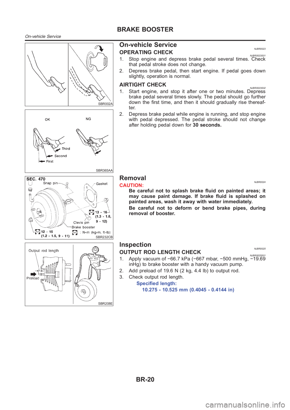
On-vehicle ServiceNJBR0023OPERATING CHECKNJBR0023S011. Stop engine and depress brake pedal several times. Check
that pedal stroke does not change.
2. Depress brake pedal, then start engine. If pedal goes down
slightly, operation is normal.
AIRTIGHT CHECKNJBR0023S021. Start engine, and stop it after one or two minutes. Depress
brake pedal several times slowly. The pedal should go further
down the first time, and then it should gradually rise thereaf-
ter.
2. Depress brake pedal while engine is running, and stop engine
with pedal depressed. The pedal stroke should not change
after holding pedal down for30 seconds.
SBR232CB
RemovalNJBR0024CAUTION:
Be careful not to splash brake fluid on painted areas; it
may cause paint damage. If brake fluid is splashed on
painted areas, wash it away with water immediately.
Be careful not to deform or bend brake pipes, during
removal of booster.
SBR208E
InspectionNJBR0025OUTPUT ROD LENGTH CHECKNJBR0025S011. Apply vacuum of −66.7 kPa (−667 mbar, −500 mmHg, −19.69
inHg) to brake booster with a handy vacuum pump.
2. Add preload of 19.6 N (2 kg, 4.4 lb) to output rod.
3. Check output rod length.
Specified length:
10.275 - 10.525 mm (0.4045 - 0.4144 in)
BRAKE BOOSTER
On-vehicle Service
BR-20
Page 2205 of 3189
InstallationNJBR0026CAUTION:
Be careful not to deform or bend brake pipes, during
installation of booster.
Replace clevis pin if damaged.
Refill with new brake fluid “DOT 4”.
Never reuse drained brake fluid.
Take care not to damage brake booster mounting bolt
thread when installing. Due to the acute angle of
installation, the threads can be damaged with the dash
panel.
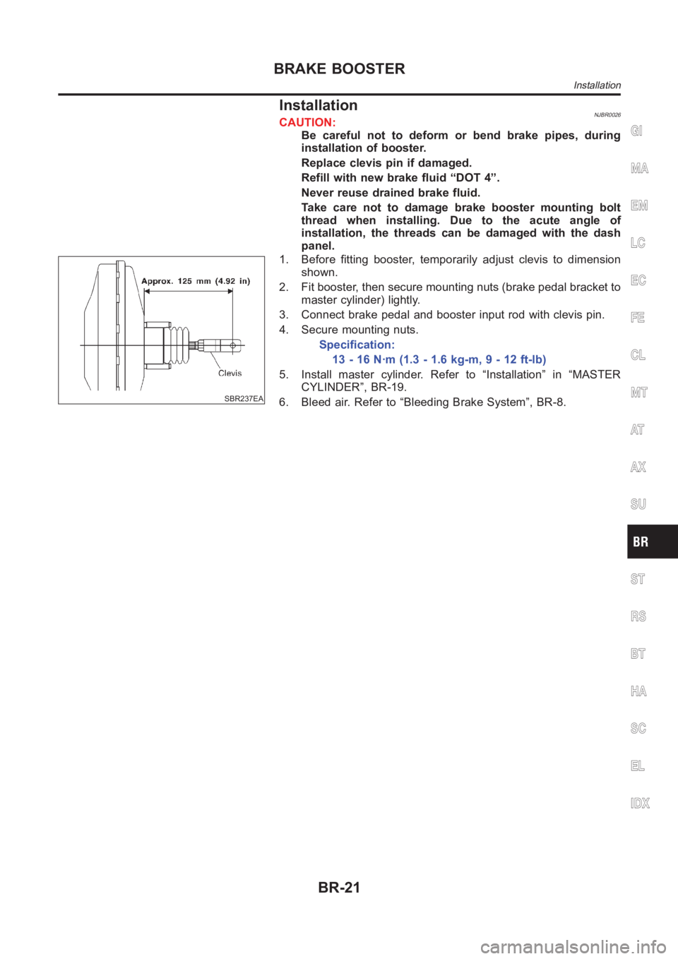
SBR237EA
1. Before fitting booster, temporarily adjust clevis to dimension
shown.
2. Fit booster, then secure mounting nuts (brake pedal bracket to
master cylinder) lightly.
3. Connect brake pedal and booster input rod with clevis pin.
4. Secure mounting nuts.
Specification:
13 - 16 N·m (1.3 - 1.6 kg-m, 9 - 12 ft-lb)
5. Install master cylinder. Refer to “Installation” in “MASTER
CYLINDER”, BR-19.
6. Bleed air. Refer to “Bleeding Brake System”, BR-8.
GI
MA
EM
LC
EC
FE
CL
MT
AT
AX
SU
ST
RS
BT
HA
SC
EL
IDX
BRAKE BOOSTER
Installation
BR-21
Page 2230 of 3189
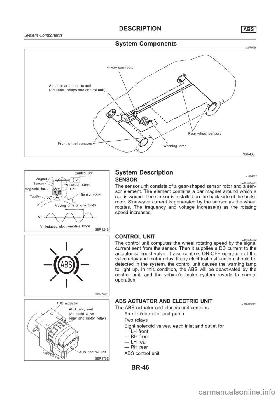
System ComponentsNJBR0086
NBR433
SBR124B
System DescriptionNJBR0087SENSORNJBR0087S01The sensor unit consists of a gear-shaped sensor rotor and a sen-
sor element. The element contains a bar magnet around which a
coil is wound. The sensor is installed on the back side of the brake
rotor. Sine-wave current is generated by the sensor as the wheel
rotates. The frequency and voltage increase(s) as the rotating
speed increases.
SBR759E
CONTROL UNITNJBR0087S02The control unit computes the wheel rotating speed by the signal
current sent from the sensor. Then it supplies a DC current to the
actuator solenoid valve. It also controls ON-OFF operation of the
valve relay and motor relay. If any electrical malfunction should be
detected in the system, the control unit causes the warning lamp
to light up. In this condition, the ABS will be deactivated by the
control unit, and the vehicle’s brake system reverts to normal
operation.
SBR176E
ABS ACTUATOR AND ELECTRIC UNITNJBR0087S03The ABS actuator and electric unit contains:
An electric motor and pump
Two relays
Eight solenoid valves, each inlet and outlet for
— LH front
—RHfront
— LH rear
— RH rear
ABS control unit
DESCRIPTIONABS
System Components
BR-46
Page 2252 of 3189
4. ABS Does Not WorkNJBR0173
1 ABS WARNING LAMP INDICATOR INSPECTION
Check that the ABS warning lamp illuminates.
Does the ABS warning lamp illuminate?
Yes Perform the self-diagnosis.
No GO TO 2.
2 WHEEL SENSOR INSPECTION
Check the wheel sensor system.
Sensor mounting inspection
Sensor pick-up inspection for iron chips
Sensor rotor inspection (e.g. Number of teeth, damaged teeth)
Sensor connector engagement inspection
OK or NG
OK Normal
NG Wheel sensor and rotor lines repair
5. Pedal Vibration and NoiseNJBR0174
1 SYMPTOM CHECK
Check the brake system for pedal vibration or noise at the engine start.
OK or NG
OK Perform the self-diagnosis.
NG GO TO 2.
2 SYMPTOM CHECK 2
Check the brake system for pedal vibration or noise when the pedal depressed lightly (just put a foot on).
CAUTION:
Under the following driving conditions, the wheel speed will fluctuates,resulting in ABS activation.
When shifting gears
High speed cornering
When a gust of wind
OK or NG
OK GO TO 3.
NG Normal
3 SYMPTOM CHECK 3
Does the symptom appear during normal braking operation?
CAUTION:
ABS may work in following driving conditions even if there is no sudden brake.
When road friction is low.
High speed cornering
When a gust of wind
OK or NG
OK GO TO 4.
NG Normal
TROUBLE DIAGNOSES FOR SYMPTOMSABS
4. ABS Does Not Work
BR-68
Page 2793 of 3189
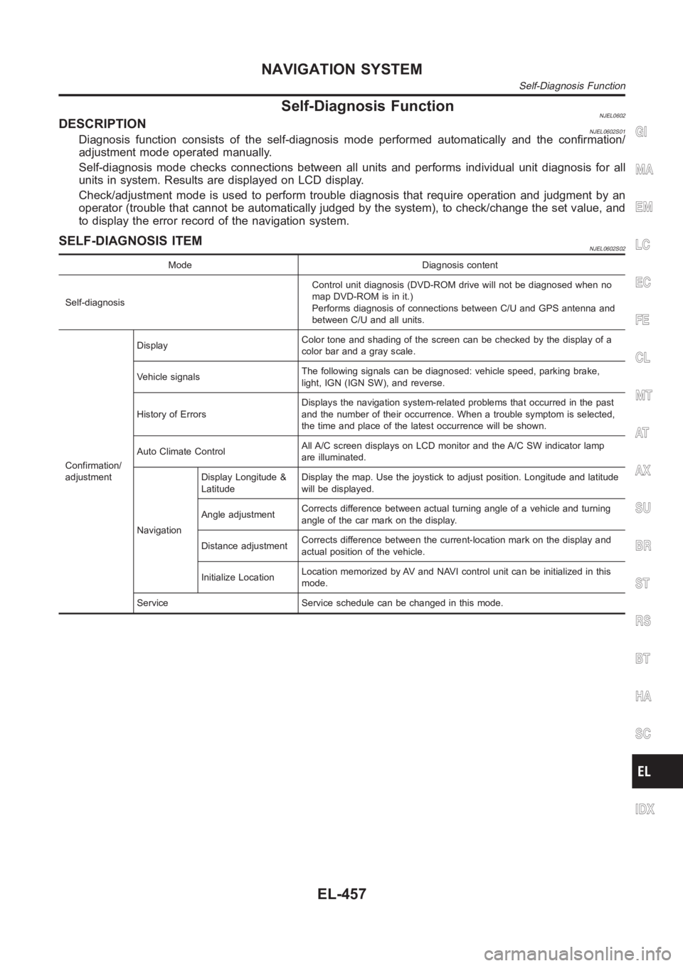
Self-Diagnosis FunctionNJEL0602DESCRIPTIONNJEL0602S01Diagnosis function consists of the self-diagnosis mode performed automatically and the confirmation/
adjustment mode operated manually.
Self-diagnosis mode checks connections between all units and performs individual unit diagnosis for all
units in system. Results are displayed on LCD display.
Check/adjustment mode is used to perform trouble diagnosis that require operation and judgment by an
operator (trouble that cannot be automatically judged by the system), to check/change the set value, and
to display the error record of the navigation system.
SELF-DIAGNOSIS ITEMNJEL0602S02
Mode Diagnosis content
Self-diagnosisControl unit diagnosis (DVD-ROM drive will not be diagnosed when no
map DVD-ROM is in it.)
Performs diagnosis of connections between C/U and GPS antenna and
between C/U and all units.
Confirmation/
adjustmentDisplayColor tone and shading of the screen can be checked by the display of a
color bar and a gray scale.
Vehicle signalsThe following signals can be diagnosed: vehicle speed, parking brake,
light, IGN (IGN SW), and reverse.
History of ErrorsDisplays the navigation system-related problems that occurred in the past
and the number of their occurrence. When a trouble symptom is selected,
the time and place of the latest occurrence will be shown.
Auto Climate ControlAll A/C screen displays on LCD monitor and the A/C SW indicator lamp
are illuminated.
NavigationDisplay Longitude &
LatitudeDisplay the map. Use the joystick to adjust position. Longitude and latitude
will be displayed.
Angle adjustmentCorrects difference between actual turning angle of a vehicle and turning
angle of the car mark on the display.
Distance adjustmentCorrects difference between the current-location mark on the display and
actual position of the vehicle.
Initialize LocationLocation memorized by AV and NAVI control unit can be initialized in this
mode.
Service Service schedule can be changed in this mode.
GI
MA
EM
LC
EC
FE
CL
MT
AT
AX
SU
BR
ST
RS
BT
HA
SC
IDX
NAVIGATION SYSTEM
Self-Diagnosis Function
EL-457
Page 2935 of 3189
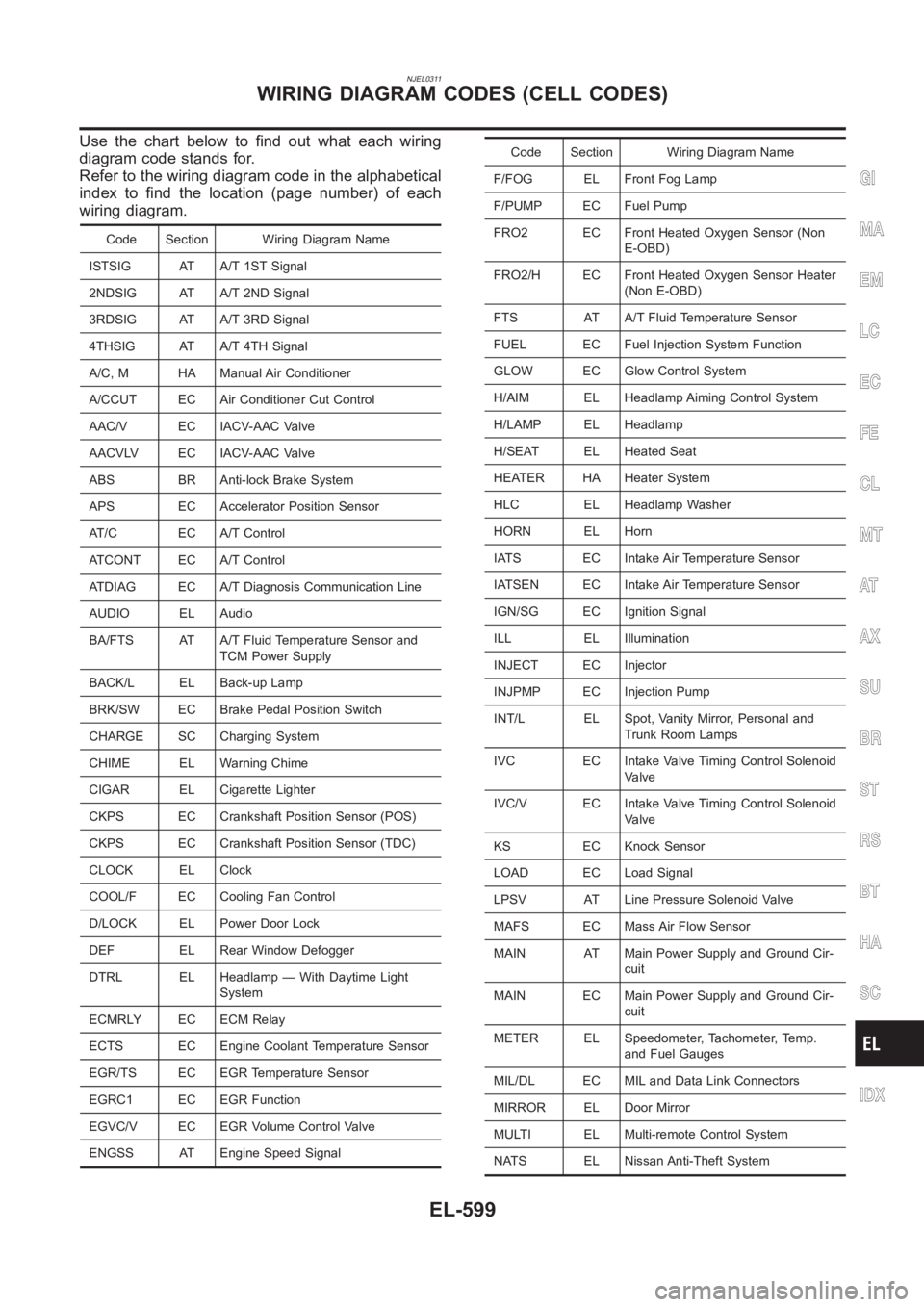
NJEL0311
Use the chart below to find out what each wiring
diagram code stands for.
Refer to the wiring diagram code in the alphabetical
index to find the location (page number) of each
wiring diagram.
Code Section Wiring Diagram Name
ISTSIG AT A/T 1ST Signal
2NDSIG AT A/T 2ND Signal
3RDSIG AT A/T 3RD Signal
4THSIG AT A/T 4TH Signal
A/C, M HA Manual Air Conditioner
A/CCUT EC Air Conditioner Cut Control
AAC/V EC IACV-AAC Valve
AACVLV EC IACV-AAC Valve
ABS BR Anti-lock Brake System
APS EC Accelerator Position Sensor
AT/C EC A/T Control
ATCONT EC A/T Control
ATDIAG EC A/T Diagnosis Communication Line
AUDIO EL Audio
BA/FTS AT A/T Fluid Temperature Sensor and
TCM Power Supply
BACK/L EL Back-up Lamp
BRK/SW EC Brake Pedal Position Switch
CHARGE SC Charging System
CHIME EL Warning Chime
CIGAR EL Cigarette Lighter
CKPS EC Crankshaft Position Sensor (POS)
CKPS EC Crankshaft Position Sensor (TDC)
CLOCK EL Clock
COOL/F EC Cooling Fan Control
D/LOCK EL Power Door Lock
DEF EL Rear Window Defogger
DTRL EL Headlamp — With Daytime Light
System
ECMRLY EC ECM Relay
ECTS EC Engine Coolant Temperature Sensor
EGR/TS EC EGR Temperature Sensor
EGRC1 EC EGR Function
EGVC/V EC EGR Volume Control Valve
ENGSS AT Engine Speed Signal
Code Section Wiring Diagram Name
F/FOG EL Front Fog Lamp
F/PUMP EC Fuel Pump
FRO2 EC Front Heated Oxygen Sensor (Non
E-OBD)
FRO2/H EC Front Heated Oxygen Sensor Heater
(Non E-OBD)
FTS AT A/T Fluid Temperature Sensor
FUEL EC Fuel Injection System Function
GLOW EC Glow Control System
H/AIM EL Headlamp Aiming Control System
H/LAMP EL Headlamp
H/SEAT EL Heated Seat
HEATER HA Heater System
HLC EL Headlamp Washer
HORN EL Horn
IATS EC Intake Air Temperature Sensor
IATSEN EC Intake Air Temperature Sensor
IGN/SG EC Ignition Signal
ILL EL Illumination
INJECT EC Injector
INJPMP EC Injection Pump
INT/L EL Spot, Vanity Mirror, Personal and
Trunk Room Lamps
IVC EC Intake Valve Timing Control Solenoid
Valve
IVC/V EC Intake Valve Timing Control Solenoid
Valve
KS EC Knock Sensor
LOAD EC Load Signal
LPSV AT Line Pressure Solenoid Valve
MAFS EC Mass Air Flow Sensor
MAIN AT Main Power Supply and Ground Cir-
cuit
MAIN EC Main Power Supply and Ground Cir-
cuit
METER EL Speedometer, Tachometer, Temp.
and Fuel Gauges
MIL/DL EC MIL and Data Link Connectors
MIRROR EL Door Mirror
MULTI EL Multi-remote Control System
NATS EL Nissan Anti-Theft System
GI
MA
EM
LC
EC
FE
CL
MT
AT
AX
SU
BR
ST
RS
BT
HA
SC
IDX
WIRING DIAGRAM CODES (CELL CODES)
EL-599
Page 3152 of 3189
Bleeding Hydraulic SystemNJST00141. Raise front end of vehicle until wheels are clear of the ground.
2. Add fluid into oil tank to specified level. Then quickly turn steer-
ing wheel fully to right and left and lightly touch steering stop-
pers.
Repeat steering wheel operation until fluid level no longer
decreases.
3. Start engine.
Repeat step 2. above.
Incomplete air bleeding will cause the following to occur. When
this happens, bleed air again.
a) Air bubbles in reservoir tank
b) Clicking noise in oil pump
c) Excessive buzzing in oil pump
Fluid noise may occur in the valve or oil pump. This is common
when the vehicle is stationary or while turning the steering wheel
slowly. This does not affect the performance or durability of the
system.
SST491B
SST090B
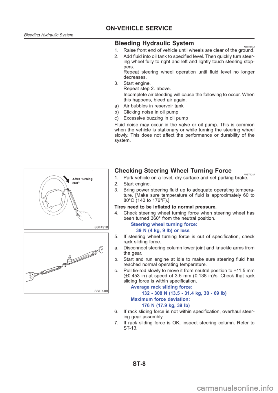
Checking Steering Wheel Turning ForceNJST00151. Park vehicle on a level, dry surface and set parking brake.
2. Start engine.
3. Bring power steering fluid up to adequate operating tempera-
ture. [Make sure temperature of fluid is approximately 60 to
80°C (140 to 176°F).]
Tires need to be inflated to normal pressure.
4. Check steering wheel turning force when steering wheel has
been turned 360° from the neutral position.
Steering wheel turning force:
39 N (4 kg, 9 lb) or less
5. If steering wheel turning force is out of specification, check
rack sliding force.
a. Disconnect steering column lower joint and knuckle arms from
the gear.
b. Start and run engine at idle to make sure steering fluid has
reached normal operating temperature.
c. Pull tie-rod slowly to move it from neutral position to±11 . 5 m m
(±0.453 in) at speed of 3.5 mm (0.138 in)/s. Check that rack
sliding force is within specification.
Average rack sliding force:
132 - 308 N (13.5 - 31.4 kg, 30 - 69 lb)
Maximum force deviation:
176 N (17.9 kg, 39 lb)
6. If rack sliding force is not within specification, overhaul steer-
ing gear assembly.
7. If rack sliding force is OK, inspect steering column. Refer to
ST-13.
ON-VEHICLE SERVICE
Bleeding Hydraulic System
ST-8
Page 3177 of 3189
Antenna - See Power antenna .....................EL-214
Anti-lock brake system - See ABS .................BR-45
Anti-lock brake system - Wiring
diagram <0011001100110011001100110011001100110011001100110011001100110011001100110011001100110011001100110011001100110011001100110011001100110011001100110011001100110011001100110011001100110011001100110011001100
1100110011001100110025[R-50
APPS1 - Wiring diagram
(QG engine)................................EC-221, EC-547
APPS2 - Wiring diagram
(QG engine)................................EC-348, EC-621
APPS3 - Wiring diagram
(QG engine)................................EC-214, EC-540
APS - Wiring diagram (YD engine) ................EC-89
Audio and A/C control removal and
installation - See Instrument panel .............BT-25
Audio <0011001100110011001100110011001100110011001100110011001100110011001100110011001100110011001100110011001100110011001100110011001100110011001100110011001100110011001100110011001100110011001100110011001100
110011001100110011001100110011[...EL-192
Auto air conditioner - Wiring diagram ..........ATC-33
Automatic amplifier .........................ATC-40, ATC-55
Automatic transaxle number............................GI-42
B
Back-up lamp switch (M/T) ............................MT-21
Back-up lamp <0011001100110011001100110011001100110011001100110011001100110011001100110011001100110011001100110011001100110011001100110011001100110011001100110011001100110011001100110011001100110011001100110011001100
28002f[-60
Ball joint (front) ...............................................SU-13
Basic inspection (QG engine) ..........EC-65, EC-444
Basic inspection (YD engine) .........................EC-48
Battery <0011001100110011001100110011001100110011001100110011001100110011001100110011001100110011001100110011001100110011001100110011001100110011001100110011001100110011001100110011001100110011001100110011001100
1100110011001100110011[......SC-3
Baulk ring (M/T) .................................MT-31, 55, 93
Blower motor (manual A/C) ............................HA-51
Blower motor ..................ATC-69, ATC-74, ATC-121
Blower resistor (manual A/C) .........................HA-51
Blower unit (manual A/C) ...............................HA-89
Blower unit <0011001100110011001100110011001100110011001100110011001100110011001100110011001100110011001100110011001100110011001100110011001100110011001100110011001100110011001100110011001100110011001100110011001100
24>7C-120
Board-on lift <0011001100110011001100110011001100110011001100110011001100110011001100110011001100110011001100110011001100110011001100110011001100110011001100110011001100110011001100110011001100110011001100110011001100
11[..GI-45
Body alignment ...............................................BT-74
Brake booster .................................................BR-20
Brake fluid change ...........................................BR-7
Brake fluid level and line check .......................BR-7
Brake hydraulic line ..........................................BR-9
Brake master cylinder ....................................BR-14
Brake pedal <0011001100110011001100110011001100110011001100110011001100110011001100110011001100110011001100110011001100110011001100110011001100110011001100110011001100110011001100110011001100110011001100110011001100
1100110025[R-12
Brake switch (QG engine) .............EC-361, EC-630
BRK/SW - Wiring diagram
(QG engine)................................EC-362, EC-631
Bulb specifications ........................................EL-598
Bumper, front <0011001100110011001100110011001100110011001100110011001100110011001100110011001100110011001100110011001100110011001100110011001100110011001100110011001100110011001100110011001100110011001100110011001100
11[.BT-7
Bumper, rear <0011001100110011001100110011001100110011001100110011001100110011001100110011001100110011001100110011001100110011001100110011001100110011001100110011001100110011001100110011001100110011001100110011001100
110025[T- 1 0
C
Camshaft (QG engine)...................................EM-32
Camshaft inspection (YD engine) ..................EM-49
Camshaft position sensor (PHASE)
(QG engine)................................EC-241, EC-563
CAN (Controller Area Network)........AT-110, AT-306
CAN (Controller Area Network) ....EL-509, 512, 530
CAN - Wiring diagram
(QG engine) ................................EC-118, EC-495
CAN - Wiring diagram ..........................EL-513, 531CAN communication
(QG engine) .....EC-117, EC-494, AT-110, AT-306
CAN communication .....................EL-509, 512, 530
Canister-See EVAP canister
(QG engine)................................EC-402, EC-721
CHARGE - Wiring diagram ............................SC-28
Charging system ............................................SC-27
CHIME - Wiring diagram...............................EL-139
CIGAR - Wiring diagram ...............................EL-171
Cigarette lighter.............................................EL-171
Circuit breaker.................................................EL-23
CKPS - Wiring diagram (YD engine) .............EC-99
Closed loop control (QG engine) .....EC-24, EC-419
Clutch cover <0011001100110011001100110011001100110011001100110011001100110011001100110011001100110011001100110011001100110011001100110011001100110011001100110011001100110011001100110011001100110011001100110011001100
110011[CL-22
Clutch disc <0011001100110011001100110011001100110011001100110011001100110011001100110011001100110011001100110011001100110011001100110011001100110011001100110011001100110011001100110011001100110011001100110011001100
1100110011[.CL-22
Clutch master cylinder ....................................CL-11
Clutch operating cylinder ................................CL-14
Clutch pedal <0011001100110011001100110011001100110011001100110011001100110011001100110011001100110011001100110011001100110011001100110011001100110011001100110011001100110011001100110011001100110011001100110011001100
110011[CL-10
Clutch release bearing .............................CL-17, 20
Clutch release mechanism .......................CL-17, 20
Clutch withdrawal lever ............................CL-17, 20
Coil spring (front)..............................................SU-9
Coil spring (rear) ............................................SU-21
Collision diagnosis..........................................RS-71
Combination lamp, rear, removal and
installation <0011001100110011001100110011001100110011001100110011001100110011001100110011001100110011001100110011001100110011001100110011001100110011001100110011001100110011001100110011001100110011001100110011001100
11[BT-47
Combination meter removal and instal-
lation - See Instrument panel ......................BT-25
Combination meter ........................................EL-110
Combination switch .........................................EL-39
Component Location (auto A/C) ...................ATC-30
Component Location (manual A/C) ................HA-21
Compression pressure (QG engine)..............EM-57
Compression pressure (YD engine) ................EM-9
Compressor clutch removal and instal-
lation (manual A/C) .....................................HA-82
Compressor clutch removal and
installation ...............................................ATC-139
Compressor precaution (manual A/C)..............HA-5
Compressor special service tool
(manual A/C) .................................................HA-9
Compressor special service tool ..................ATC-11
Condenser <0011001100110011001100110011001100110011001100110011001100110011001100110011001100110011001100110011001100110011001100110011001100110011001100110011001100110011001100110011001100110011001100110011001100
24>7&-144
Connecting rod (QG engine) .........................EM-86
Connecting rod (YD engine) ..........................EM-72
Connecting rod bearing clearance
(QG engine)................................................EM-87
Connecting rod bearing clearance
(YD engine) ................................................EM-77
Connecting rod bushing clearance
(QG engine)................................................EM-87
Connecting rod bushing clearance
(YD engine) ................................................EM-79
Console box - See Instrument panel ..............BT-25
CONSULT for engine (QG engine) ..EC-88, EC-467
CONSULT for engine (YD engine) .................EC-39
Control lever (M/T) .........................................MT-29
Control unit .................................................ATC-114
Controller Area Network (CAN)........AT-110, AT-306
Controller Area Network (CAN) ....EL-509, 512, 530
Converter housing installation .........AT-412, AT-509
GI
MA
EM
LC
EC
FE
CL
MT
AT
AX
SU
BR
ST
RS
BT
HA
SC
EL
ALPHABETICAL INDEX
IDX-3