Page 39 of 3189
Nickel Metal Hydride Battery Replacement=NJGI0007S06CONSULT-II contains a nickel metal hydride battery. When replacing the battery obey the following:
WARNING:
Replace the nickel metal hydride battery with Genuine CONSULT-II batteryonly. Use of another bat-
tery may present a risk of fire or explosion. The battery may present a fire orchemicalburnhazardif
mistreated. Do not recharge, disassemble of dispose of in fire.
Keep the battery out of reach of children and discard used battery conforming to the local regulations.
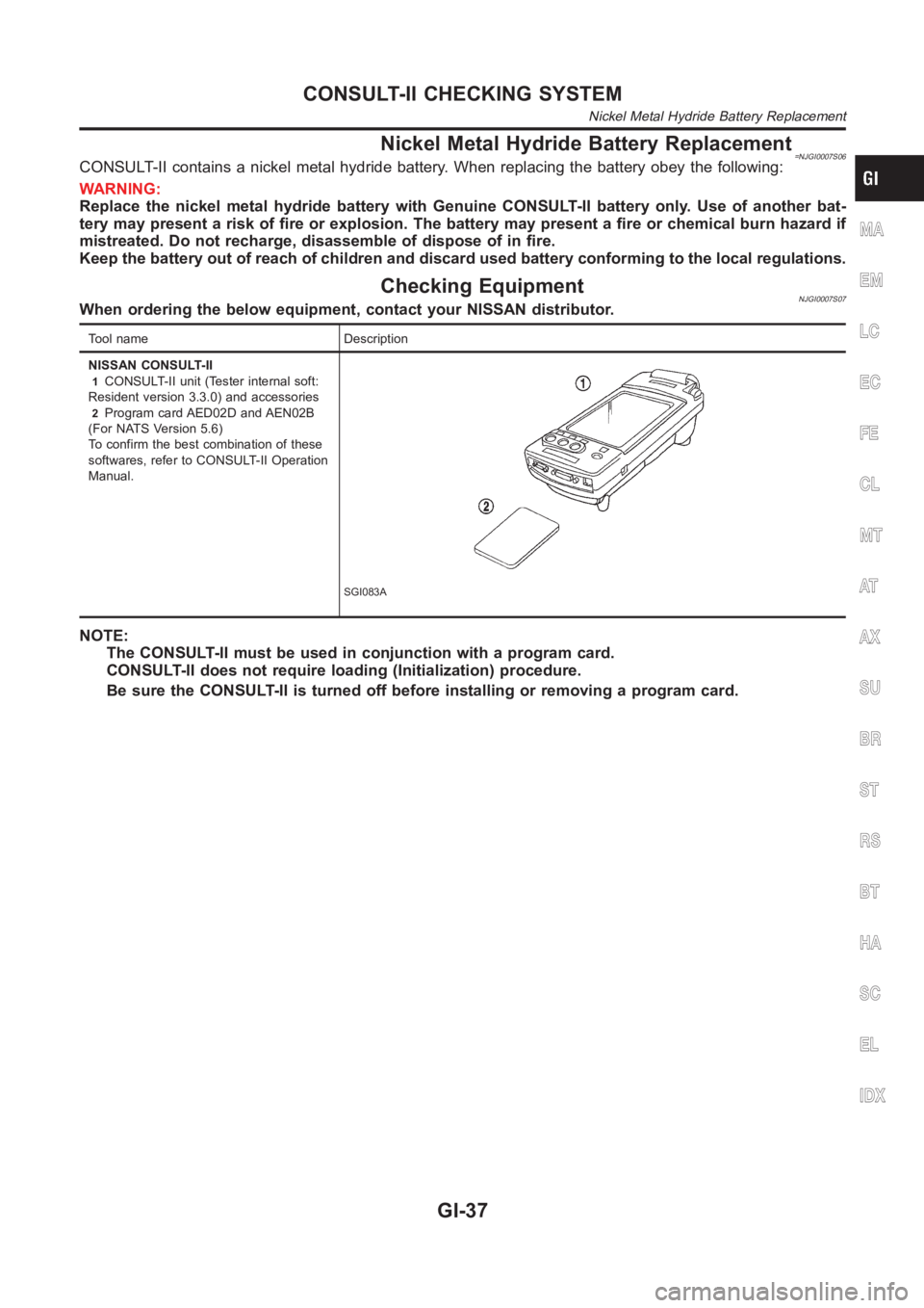
Checking EquipmentNJGI0007S07When ordering the below equipment, contact your NISSAN distributor.
Tool name Description
NISSAN CONSULT-II
1CONSULT-II unit (Tester internal soft:
Resident version 3.3.0) and accessories
2Program card AED02D and AEN02B
(For NATS Version 5.6)
To confirm the best combination of these
softwares, refer to CONSULT-II Operation
Manual.
SGI083A
NOTE:
The CONSULT-II must be used in conjunction with a program card.
CONSULT-II does not require loading (Initialization) procedure.
Be sure the CONSULT-II is turned off before installing or removing a program card.
MA
EM
LC
EC
FE
CL
MT
AT
AX
SU
BR
ST
RS
BT
HA
SC
EL
IDX
CONSULT-II CHECKING SYSTEM
Nickel Metal Hydride Battery Replacement
GI-37
Page 521 of 3189
![NISSAN ALMERA N16 2003 Electronic Repair Manual DTC P0171 FUEL INJECTION SYSTEM FUNCTION
EC-191
[QG (WITH EURO-OBD)]
C
D
E
F
G
H
I
J
K
L
MA
EC
6.CHECK FUNCTION OF INJECTORS
With CONSULT-II
1. Start engine.
2. Perform “POWER BALANCE” in “A](/manual-img/5/57350/w960_57350-520.png "NISSAN ALMERA N16 2003 Electronic Repair Manual DTC P0171 FUEL INJECTION SYSTEM FUNCTION
EC-191
[QG (WITH EURO-OBD)]
C
D
E
F
G
H
I
J
K
L
MA
EC
6.CHECK FUNCTION OF INJECTORS
With CONSULT-II
1. Start engine.
2. Perform “POWER BALANCE” in “A")
DTC P0171 FUEL INJECTION SYSTEM FUNCTION
EC-191
[QG (WITH EURO-OBD)]
C
D
E
F
G
H
I
J
K
L
MA
EC
6.CHECK FUNCTION OF INJECTORS
With CONSULT-II
1. Start engine.
2. Perform “POWER BALANCE” in “ACTIVE TEST” mode with
CONSULT-II.
3. Make sure that each circuit produces a momentary engine
speed drop.
Without CONSULT-II
1. Start engine.
2. Listen to each injector operating sound.
OK or NG
OK >> GO TO 7.
NG >> Perform trouble diagnosis for EC-375, "
INJECTOR CIRCUIT" .
7.CHECK INJECTOR
1. Confirm that the engine is cooled down and there are no fire hazards near the vehicle.
2. Turn ignition switch “OFF”.
3. Disconnect injector harness connectors.
4. Remove injector gallery assembly. Refer to EM-26, "
FUEL INJECTOR AND FUEL TUBE" .
Keep fuel hose and all injectors connected to injector gallery.
The injector harness connectors should remain connected.
5. Disconnect all ignition coil harness connectors.
6. Prepare pans or saucers under each injector.
7. Crank engine for about 3 seconds. Make sure that fuel sprays
out from injectors.
OK or NG
OK >> GO TO 8.
NG >> Replace injectors from which fuel does not spray out.
Always replace O-ring with new ones.
PBIB0133E
Clicking noise should be heard.
MEC703B
Fuel should be sprayed evenly for each injector.
SEF595Q
Page 528 of 3189
EC-198
[QG (WITH EURO-OBD)]
DTC P0172 FUEL INJECTION SYSTEM FUNCTION
7. CHECK INJECTOR
1. Remove injector assembly. Refer to EM-26, "
FUEL INJECTOR AND FUEL TUBE" .
Keep fuel hose and all injectors connected to injector gallery.
2. Confirm that the engine is cooled down and there are no fire hazards near the vehicle.
3. Disconnect injector harness connectors.
The injector harness connectors should remain connected.
4. Disconnect all ignition coil harness connectors.
5. Prepare pans or saucers under each injectors.
6. Crank engine for about 3 seconds.
Make sure fuel does not drip from injector.
OK or NG
OK (Does not drip.)>>GO TO 8.
NG (Drips.)>>Replace the injectors from which fuel is dripping. Always replace O-ring with new one.
8. CHECK INTERMITTENT INCIDENT
Refer to EC-109, "
TROUBLE DIAGNOSIS FOR INTERMITTENT INCIDENT" .
>>INSPECTION END
Page 2211 of 3189
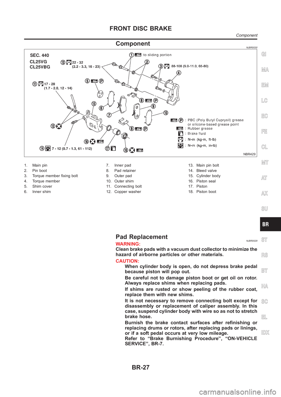
ComponentNJBR0030
NBR429
1. Main pin
2. Pin boot
3. Torque member fixing bolt
4. Torque member
5. Shim cover
6. Inner shim7. Inner pad
8. Pad retainer
9. Outer pad
10. Outer shim
11. Connecting bolt
12. Copper washer13. Main pin bolt
14. Bleed valve
15. Cylinder body
16. Piston seal
17. Piston
18. Piston boot
Pad ReplacementNJBR0029WARNING:
Clean brake pads with a vacuum dust collector to minimize the
hazard of airborne particles or other materials.
CAUTION:
When cylinder body is open, do not depress brake pedal
because piston will pop out.
Be careful not to damage piston boot or get oil on rotor.
Always replace shims when replacing pads.
If shims are rusted or show peeling of the rubber coat,
replace them with new shims.
It is not necessary to remove connecting bolt except for
disassembly or replacement of caliper assembly. In this
case, suspend cylinder body with wire so as not to stretch
brake hose.
Burnish the brake contact surfaces after refinishing or
replacing drums or rotors, after replacing pads or linings,
or if a soft pedal occurs at very low mileage.
Refer to “Brake Burnishing Procedure”, “ON-VEHICLE
SERVICE”, BR-7.
GI
MA
EM
LC
EC
FE
CL
MT
AT
AX
SU
ST
RS
BT
HA
SC
EL
IDX
FRONT DISC BRAKE
Component
BR-27
Page 2212 of 3189
SBR976B
SBR932C
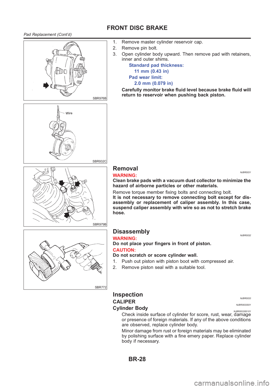
1. Remove master cylinder reservoir cap.
2. Remove pin bolt.
3. Open cylinder body upward. Then remove pad with retainers,
inner and outer shims.
Standard pad thickness:
11 m m ( 0 . 4 3 i n )
Pad wear limit:
2.0mm(0.079in)
Carefully monitor brake fluid level because brake fluid will
return to reservoir when pushing back piston.
SBR979B
RemovalNJBR0031WARNING:
Clean brake pads with a vacuum dust collector to minimize the
hazard of airborne particles or other materials.
Remove torque member fixing bolts and connecting bolt.
It is not necessary to remove connecting bolt except for dis-
assembly or replacement of caliper assembly. In this case,
suspend caliper assembly with wire so as not to stretch brake
hose.
SBR772
DisassemblyNJBR0032WARNING:
Do not place your fingers in front of piston.
CAUTION:
Do not scratch or score cylinder wall.
1. Push out piston with piston boot with compressed air.
2. Remove piston seal with a suitable tool.
InspectionNJBR0033CALIPERNJBR0033S01Cylinder BodyNJBR0033S0101Check inside surface of cylinder for score, rust, wear, damage
or presence of foreign materials. If any of the above conditions
are observed, replace cylinder body.
Minor damage from rust or foreign materials may be eliminated
by polishing surface with a fine emery paper. Replace cylinder
body if necessary.
FRONT DISC BRAKE
Pad Replacement (Cont’d)
BR-28
Page 2215 of 3189
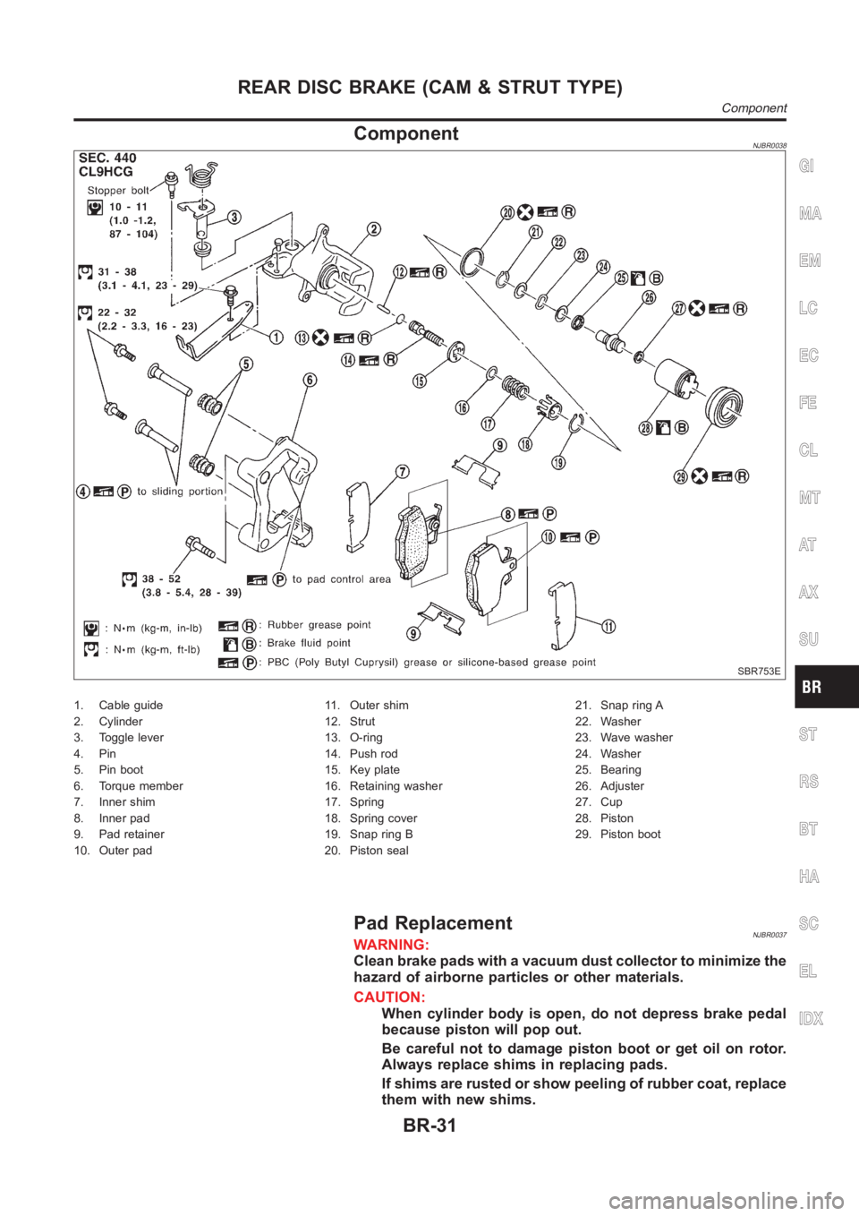
ComponentNJBR0038
SBR753E
1. Cable guide
2. Cylinder
3. Toggle lever
4. Pin
5. Pin boot
6. Torque member
7. Inner shim
8. Inner pad
9. Pad retainer
10. Outer pad11. Outer shim
12. Strut
13. O-ring
14. Push rod
15. Key plate
16. Retaining washer
17. Spring
18. Spring cover
19. Snap ring B
20. Piston seal21. Snap ring A
22. Washer
23. Wave washer
24. Washer
25. Bearing
26. Adjuster
27. Cup
28. Piston
29. Piston boot
Pad ReplacementNJBR0037WARNING:
Clean brake pads with a vacuum dust collector to minimize the
hazard of airborne particles or other materials.
CAUTION:
When cylinder body is open, do not depress brake pedal
because piston will pop out.
Be careful not to damage piston boot or get oil on rotor.
Always replace shims in replacing pads.
If shims are rusted or show peeling of rubber coat, replace
them with new shims.
GI
MA
EM
LC
EC
FE
CL
MT
AT
AX
SU
ST
RS
BT
HA
SC
EL
IDX
REAR DISC BRAKE (CAM & STRUT TYPE)
Component
BR-31
Page 2217 of 3189
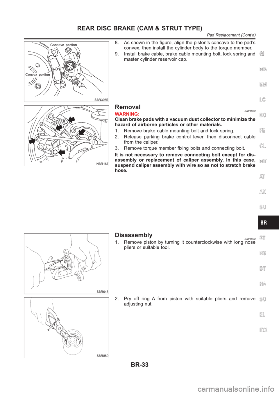
SBR307E
8. As shown in the figure, align the piston’s concave to the pad’s
convex, then install the cylinder body to the torque member.
9. Install brake cable, brake cable mounting bolt, lock spring and
master cylinder reservoir cap.
NBR167
RemovalNJBR0039WARNING:
Clean brake pads with a vacuum dust collector to minimize the
hazard of airborne particles or other materials.
1. Remove brake cable mounting bolt and lock spring.
2. Release parking brake control lever, then disconnect cable
from the caliper.
3. Remove torque member fixing bolts and connecting bolt.
It is not necessary to remove connecting bolt except for dis-
assembly or replacement of caliper assembly. In this case,
suspend caliper assembly with wire so as not to stretch brake
hose.
SBR646
DisassemblyNJBR00401. Remove piston by turning it counterclockwise with long nose
pliers or suitable tool.
SBR889
2. Pry off ring A from piston with suitable pliers and remove
adjusting nut.
GI
MA
EM
LC
EC
FE
CL
MT
AT
AX
SU
ST
RS
BT
HA
SC
EL
IDX
REAR DISC BRAKE (CAM & STRUT TYPE)
Pad Replacement (Cont’d)
BR-33
Page 2223 of 3189
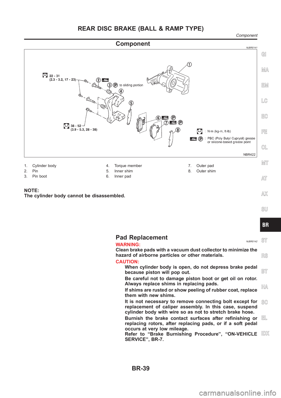
ComponentNJBR0141
NBR422
1. Cylinder body
2. Pin
3. Pin boot4. Torque member
5. Inner shim
6. Inner pad7. Outer pad
8. Outer shim
NOTE:
The cylinder body cannot be disassembled.
Pad ReplacementNJBR0142WARNING:
Clean brake pads with a vacuum dust collector to minimize the
hazard of airborne particles or other materials.
CAUTION:
When cylinder body is open, do not depress brake pedal
because piston will pop out.
Be careful not to damage piston boot or get oil on rotor.
Always replace shims in replacing pads.
If shims are rusted or show peeling of rubber coat, replace
them with new shims.
It is not necessary to remove connecting bolt except for
replacement of caliper assembly. In this case, suspend
cylinder body with wire so as not to stretch brake hose.
Burnish the brake contact surfaces after refinishing or
replacing rotors, after replacing pads, or if a soft pedal
occurs at very low mileage.
Refer to “Brake Burnishing Procedure”, “ON-VEHICLE
SERVICE”, BR-7.
GI
MA
EM
LC
EC
FE
CL
MT
AT
AX
SU
ST
RS
BT
HA
SC
EL
IDX
REAR DISC BRAKE (BALL & RAMP TYPE)
Component
BR-39
![NISSAN ALMERA N16 2003 Electronic Repair Manual EC-198
[QG (WITH EURO-OBD)]
DTC P0172 FUEL INJECTION SYSTEM FUNCTION
7. CHECK INJECTOR
1. Remove injector assembly. Refer to EM-26, "
FUEL INJECTOR AND FUEL TUBE" .
Keep fuel hose and all inje](/manual-img/5/57350/w960_57350-527.png "NISSAN ALMERA N16 2003 Electronic Repair Manual EC-198
[QG (WITH EURO-OBD)]
DTC P0172 FUEL INJECTION SYSTEM FUNCTION
7. CHECK INJECTOR
1. Remove injector assembly. Refer to EM-26, \"
FUEL INJECTOR AND FUEL TUBE\" .
Keep fuel hose and all inje")